RapidWave RapidLink 54 Troubleshooting guide

Base Station/NMC DRAFT 1.1
RapidLink 54 Wireless Point-to-MultiPoint Network
Installation Guide/Users Manual
1

Rev. 0.1 10-6-04
RapidLink is a trademark of RapidWave, Inc. Other trademarks or brand names mentioned herein are trademarks or
registered trademarks of their respective companies.
RapidWave, Inc.
6296 A San Ignacio Ave.
San Jose, CA 95119
Telephone: (408) 363-5984
Fax: (408) 363-5972
URL: http://www.rapidwaveinc.com
Any changes or modifications not expressly approved by the party responsible for compliance could void the user's
authority to operate the equipment.
Copyright © RapidWave, Inc. – All Rights Reserved
No part of this document may be copied or reproduced in any form or by any means without the prior written consent
of RapidWave, Inc.
RapidWave makes no warranties with respect to this documentation and disclaims any implied warranties of
merchantability, quality, or fitness for any particular purpose. The information in this document is subject to change
without notice. RapidWave reserves the right to make revisions to this publication without obligation to notify any
person or entity of any such changes.
RapidLink 54 Wireless Point-to-Multipoint Networks
2 Installation Guide

Table of Contents:
1. For your safety...........................................................................................…..4
2. Components...........................……………………………...........................…...5
3. Installation................................……………………………….......……………...5
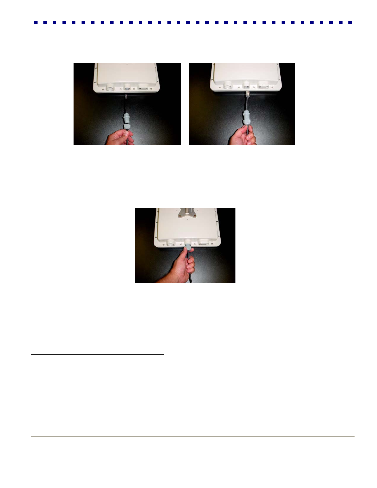
3.1 Connecting the Outdoor Units……………………………………..…….5
3.2 Mounting External Sector Antennas…………………………………….7
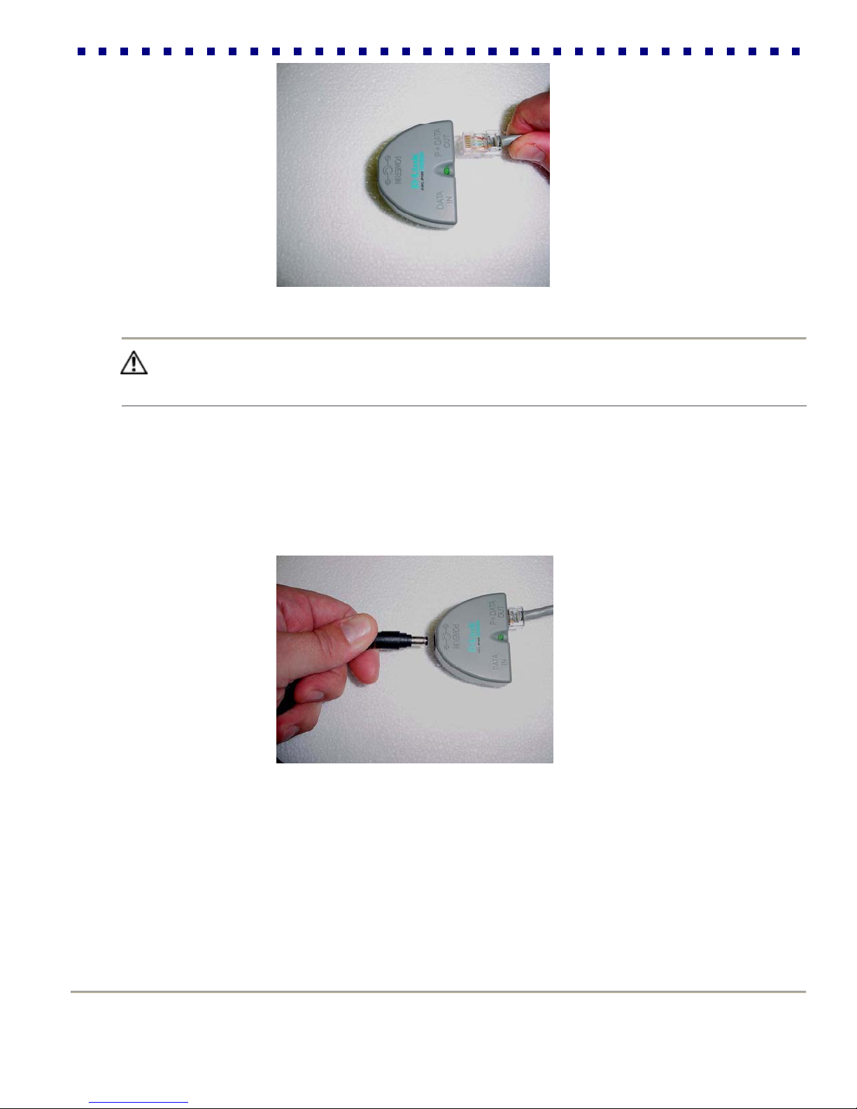
3.3 Connecting the Indoor Units (Power-over-Ethernet Injectors)………..9
4. Basic Base Station Radio Configuration………………………………… …….12
4.1 Overview of the RapidLink 54 Web Interface…………………………12
4.2 Setting Basic Network Parameters…………………………………….12
5. Advanced Configuration Options and Tools……………………………………13
5.1 Advanced Page…………………………………………………………..14
5.2 Security………………………………………………………………..…..19
5.3 Firmware Upgrade………………………………………………………..22
6. RapidLink 54 PtMP Network Management Center…………………………….23
6.1 Installing RapidLink 54 NMC……………………………………………23
6.2 Adding, Modifying & Deleting Sectors………………………………….23
6.3 Adding, Modifying & Deleting Users/Services…………………………26
6.4 Upgrading Application Files……………………………………………...28
7. Notes………………………………………………………………………………...30
8. Warranty…………………………………………………………………………….31
__________________________________________________________________________
RapidLink 54 Wireless Point-to-Multipoint Networks
3 Installation Guide

RapidLink 54 Wireless Point-to-Multipoint Networks
4 Installation Guide
Section 1: For Your Safety
WARNING
Use extreme care when installing equipment or working near power lines.
CAUTION
When the unit is in operation, avoid standing directly in
front of the antenna. Strong RF fields are present when
the transmitter is on.
The antenna used for this transmitter must be installed to provide a
separation distance of at least 150 cm from all persons.
This Point-to-MultiPoint device and its antenna(s) must not be
co-located or operating in conjunction with any other antenna or
transmitter.
This equipment has been tested and found to comply with the limits for
a Class A digital device, pursuant to part 15 of the FCC Rules. These
limits are designed to provide reasonable protection against harmful
interference when the equipment is operated in a commercial
environment. This equipment generates, uses, and can radiate radio
frequency energy and, if not installed and used in accordance with the
instruction manual, may cause harmful interference to radio
communications. Operation of this equipment in a residential area is
likely to cause harmful interference in which case the user will be
required to correct the interference at his own expense.

Section 2: Components
Model RL54-BS-1790 comes with an External 17dBi gain 90°Vertical Polarized sector antenna
RapidLink 54 Wireless Point-to-Multipoint Networks
5 Installation Guide
N-Type RF
Bulkhead Cable
Adapter
BS Radio Unit with
weatherproof cover
17 dBi External
90°(V) Sector
Antenna Weatherproof
Wire Gland
Indoor Power-
Over-Ethernet
Adapter Base Unit
N-Type-to-N-Type
2 ft RF Cable Indoor AC/DC
Power Adapter
Mounting
Hardware
Section 3: Installation
3.1 Connecting the Outdoor Units
NOTICE To meet regulatory restrictions, RapidWaves’ external antenna configuration and any
external antenna must be professional installed.
Step 1: Select optimal locations for the outdoor base station units. Consider the following criteria to ensure maximum
performance and stability of your wireless connection:

Best signal path possible, ideally the highest spot overlooking prospective coverage area. It is always
recommended to have a professional site survey done prior to installation
Fresnel zone clearance
Less than 320 feet of total Power-Over-Ethernet UTP cable, the shorter the better
Optimal transmission range (visit the online range calculator at http://www.rapidwaveinc.com)
Step 2: Attach the outdoor units mounting brackets.
Tip Only use the supplied extension bracket if necessary, otherwise it is recommended to mount the antenna-
mounting bracket directly to the female pole-mounting bracket as depicted below. If the extension bracket is
required for appropriate installation, than it will also be necessary to remount the antenna bracket on the back of the
antenna, to maintain an upright and vertical position.
Step 3: Install “User Supplied” CAT5 Weatherized Ethernet straight-through cable.
------ Do not exceed 320 feet (100 Meters) of cable per installation------
Step 4: Determine the appropriate routing length for your Ethernet cable and cut to length.
Step 5: Splice and crimp indoor mounting side of the CAT5 Ethernet Cable with an RJ-45 connector.
RapidLink 54 Wireless Point-to-Multipoint Networks
6 Installation Guide

Step 6: The RL54 mounting side of the Ethernet cable must first be routed through the supplied weatherized wiring
gland, than spliced and crimped with a RJ-45 connector. It is Highly recommended that you test the cable with an RJ-
45 wiring tester before final installation.
RapidLink 54 Wireless Point-to-Multipoint Networks
7 Installation Guide
Step 7: Connect the RJ-45 to the female connecter located directly inside the enclosure, make sure the
connection is locked in place before tightening the gland.
Step 8: Tighten the gland to the enclosure and than tighten the compression nut around the Ethernet
cable
Step 9: Mount the outdoor units to the predetermined Base Station location you chose in step 1
3.2 Mounting External Sector Antenna
NOTICE To meet regulatory restrictions, RapidWaves’ external antenna configuration and any external antenna
must be professional installed.

NOTE All external antenna configurations will come with an N-type Bulkhead adapter installed at the bottom of
the main radio enclosure.
Step 1: Carefully attach one end of the supplied N-type RF cable to the main radio unit first and than install to the
permanent poll location.
Step 2: Mount the external antenna with supplied mounting brackets to the same poll and attach the other end of the
RF cable to the antenna.
NOTE When determining the location of the external antenna, keep in mind to not exceed the distance of the
supplied RF cable
Tip RapidWave recommends mounting all external antennas either “under” or “back-to-back” with the main radio
enclosure unit (as shown above). This will insure proper RF cable routing and maintain the best guard against
the weather. Adding any other RF cable may decrease the performance of the connection.
Step 3: After mounting the outdoor units, loosen the pole mounting clamp (sector antenna only) just enough to maneuver to the
ideal vertically and horizontally position to obtain maximum sector coverage.
Tip At this point it is recommended that you test the physical RF parameters of your Base Station antenna alignment
to assure desired cover area will be receiving adequate signal for CPE installations.
RapidLink 54 Wireless Point-to-Multipoint Networks
8 Installation Guide

Step 4: Secure the outdoor unit’s Ethernet cable (that you attached to the bottom of the outdoor unit) along the length
of the pole using tie-wraps, run the cable toward the inside of the building.
Tip For best results, secure this cable to the pole at least every 10 feet with tie-wraps.
3.3 Connecting the Indoor Units (Power-over-Ethernet Injectors)
The indoor unit is the point at which the outdoor units connect with your indoor LAN. More specifically, the indoor unit
connects your wireless unit to the network and transmits both data and power to the outdoor unit.
Perform the following steps (1-6) to connect the indoor unit of the wireless outdoor unit.
Step 1: Place the indoor unit in an appropriate location that meets the following criteria:
The distance from the outdoor unit to the indoor Power-Over-Ethernet adapter must not exceed the length of
your Ethernet cable after attached to the bottom of the outdoor unit
The distance from the indoor unit to the Ethernet network backbone device (e.g., hub or switch) must not
exceed 320 ft (100 meters)
The distance from the indoor unit to an available AC outlet must not exceed the length of the supplied power
cable
Step 2: Bring the Ethernet cable into to the wiring closet (where the indoor unit is located), and plug the RJ-45
connector into the combined Ethernet/power output port (P + Data Out) on the front panel of the indoor unit.
RapidLink 54 Wireless Point-to-Multipoint Networks
9 Installation Guide

RapidLink 54 Wireless Point-to-Multipoint Networks
10 Installation Guide
Caution Connecting any device other than the outdoor unit to the indoor unit may cause permanent hardware
damage. Do not confuse the RJ-45 connector of the outdoor unit’s with that of the Ethernet cable connected to
your backbone device.
Step 3: Connect one end of the brick style power adapter cable to the power jack (Power In) on the rear panel of the
indoor unit, and plug the other end of the power cable into the AC wall outlet.
Step 4: Check the front panel of the indoor unit to make certain that the power LED is on.If the power LED is not on,
confirm that the power cable is securely connected and that your power source is operational.

Step 5: Plug your Ethernet patch cable into the Ethernet input port (Data In) of the indoor unit and into the data port of
your backbone device.
RapidLink 54 Wireless Point-to-Multipoint Networks
11 Installation Guide
Caution Do not confuse the Ethernet input port with the Ethernet/Power output port. To avoid permanent hardware
damage, make certain that you connect your backbone device to the Ethernet input port (not the Ethernet/Power
output port).
Step 6: Check the link LED on your backbone device to confirm that it is on.
Congratulations! At this point, you have completed all the hardware related steps necessary to
establish your point-to-multipoint wireless link. However, your wireless link is not yet operational. The
next section will describe basic software configuration and antenna alignment procedures necessar
y
to activate the wireless network.

Section 4: Basic Base Station Radio Configuration
4.1 Overview of the RapidLink 54 PtMP Base Station Web Interface
All basic radio configuration management parameters are accessible through an embedded web server interface
called the Wireless Link Manager (WLM). Using a web browser, you can easily log into the web server of your wireless
unit. From this user-friendly interface, you can communicate with any RapidLink 54 Base Station and perform
configuration, management and trouble-shooting tasks for this local radio.
4.2 Setting Basic Base Station Radio Parameters
In this section, you will log into the RapidLink 54 WLM for the first time and modify your radios default settings.
NOTICE You may need to change your computers TCP/IP local area connection setting to an IP
range that is compatible with the default IP of the Base Station
Step 1: Load your web browser.
Step 2: Type the factory default IP address: 192.168.1.54 into the address field of your browser and press Enter.This
will load the RapidLink 54 WLM.
Step 3: Enter the default (Case Sensitive) Login: admin and Password: rl54 when prompted and click Enter.
Tip It is strongly recommended that you change the Password and Login as soon as you have
completed the basic configuration by clicking on the Security tab. See section 5.2 under Security for
full details on changing password.
RapidLink 54 Wireless Point-to-Multipoint Networks
12 Installation Guide

Now you will see the RapidWave 54 WLM. Along the top of the page, you will find five tabs that contain all the
configuration options available for RapidLink 54 Base Stations. These tabs are: Setup, Advanced, Security, Antenna
Align and Upgrade. You will use the Setup page to set network parameters
Step 4: Enter a new IP Address for the Base Station (the IP address of each device must be unique)
Write down your new IP Address for future reference in the NOTES section of this Installation Guide. If the IP
is changed and than forgotten, you may need to reset all default values to recover, disrupting service to all
users
Step 5: Enter a Subnet Mask (if different than the default value).
Step 6: Enter the current Gateway Address to which you are connected.
Step 7: Enter the Name of your Base Station Sector.
Step 8: Click Apply.
Step 9: To put the changes into effect, click Restart, a dialog box will appear, click OK. The Base Station will then
restart.
Section 5: Advanced Configuration Options and Tools
From radio-related parameters and security algorithms to diagnostic tools and firmware upgrade utilities, the WLM
offers numerous options that help you effectively manage the system and achieve the highest performance possible.
This section describes RapidLink 54’s advanced configuration options, which you can find in the following categories:
Advanced Security Antenna Align Upgrade
Accessing the advanced options is simple. From the RapidLink 54 WLM, simply click on the tab corresponding to the
category you need. The following sub-sections will explain how to configure each parameter within these categories.
Tip While the options differ, each page functions similarly. As you read the next subsections, keep in mind that
regardless of the page, any change you make can only go into effect if you click Apply. If you do not click Apply
before moving to the next page, your changes will be lost.
Also be advised that certain parameters in the Advanced and Security pages require you to restart the system in
order to take effect. In such cases, go back to the setup page and click on Restart. If you know that you will be
making more changes, you can complete all other changes, and restart the system later.
RapidLink 54 Wireless Point-to-Multipoint Networks
13 Installation Guide

5.1 Advanced Page
This page allows you to control radio-related parameters, including Transmit Mode, Data Rate, SSID, Channel and
Furthest Link Distance. These parameters must be identical on both sides of all wireless links. Therefore, any
change on the Base Station should also be executed for all CPE’s. This sub-section explains the options in each field
of the Advanced page.
Tip Transmit Mode, Data Rate, and Channel settings are interdependent. Data Rate and Channel are always
updated according to the Transmit Mode setting. It is therefore recommended that you select the Transmit Mode
first and follow the instructions below in the order that they are presented.
Set Transmit Mode:
Simply click the drop-down menu in the Transmit Mode field and select either Turbo or Standard Mode. Data Rate
and Channel options will then update according to the new setting.
RapidLink 54 Wireless Point-to-Multipoint Networks
14 Installation Guide

RapidLink 54 Wireless Point-to-Multipoint Networks
15 Installation Guide
Set Data Rate:
RapidLink 54 supports several possible data rates ranging from 6 to 108 Mbps. The highest transmission rate is 108
Mbps, with automatic fallback rates that allow the unit to operate in the most efficient manner. By default, the system
automatically switches between these rates to maximize coverage. However, you may wish to select a fixed Data Rate
based on your specific objectives or needs.
Step 1: To adjust this parameter, click the drop-down menu in the Data Rate field and select the desired rate.

RapidLink 54 Wireless Point-to-Multipoint Networks
16 Installation Guide
Note The default setting, Auto, is recommended.
Auto: When the Data Rate is set to Auto, the Base Station will follow an algorithm to determine the
highest bit rate possible for communication with all of the CPE’s on the network.
Fixed Bit Rate: The Auto setting is disabled by selecting a specific bit rate to be used for the wireless link.
This would be appropriate when operating in a well-understood environment, and when full rate operation is
not possible. If you choose to set a fixed rate It is recommended that you start with the lowest bit rate, working
your way up to the highest achievable data rate.
Step 2: The Antenna Align section should be used to check signal strength and help determine the furthest regions of
your sector coverage. This is a good “Site Survey” tool to help outline your sectors boundaries and “dead spots” prior
to the deployment of CPE’s. Be advised that different data rates have different sensitivities, which will impact range.
Once multiple CPE’s have been installed within the same Base Station sector, this tool will no longer be functional, as
you will have no way to determine which CPE on the network is providing which signal strength.
Enter SSID:
The SSID is a service set identifier that uniquely describes your Base Stations sector and all of the CPE’s that will
receive signal from this Base Station. Always use the same SSID for all CPE’s in the covered sector.

Set Channel:
Channels are used to set the center frequency used to transmit data over the wireless link. You can avoid active
interference by switching channels if you suspect interferers operating on the same frequency. Available channels
shown in the drop-down menu are based on local regulatory requirements.
To set the Channel: Click the drop-down menu in the Channel field and select the desired frequency.
Five channels are available in Transmit Mode Standard
Two channels are available in Transmit Mode Turbo
Note Always set all CPE’s to the same channel as the host Base Station
RapidLink 54 Wireless Point-to-Multipoint Networks
17 Installation Guide

Tip If active interference is not an issue, it is recommended that you choose the default
Channel (lowest frequency) in order to maximize range.
Set Furthest Link Distance:
Entering the correct Link Distance maximizes performance for all users by ensuring the system is ideally tuned to the
distance between the Base Station and the furthest CPE within the sector. You can change this anytime by clicking the
drop-down Link Distance menu and selecting the desired setting as new further CPE’s are introduced to the network.
RapidLink 54 Wireless Point-to-Multipoint Networks
18 Installation Guide

5.2 Security
This section describes the parameters available through the Security menu. RapidLink 54 provides two forms of
security, access control and privacy. Access control is achieved by MAC address authentication, which allows only
known devices to associate with the Base Station and establish a wireless connection. Another component of access
control is the password protected user interface, which can be configured on the Security page. Privacy is
accomplished by enabling encryption that prevents rogue stations or wireless sniffers from decoding any captured
data. RapidLink 54 provides 128-bit WEP encryption option on the Security page.
Changing your Password
We recommend that you change your Login and Password from the factory default setting to authenticate the identity
of the RapidLink 54 administrator and ensure that no unauthorized users gain access to the WLM.
To change your Login and Password, type a new Login name (16 characters maximum). Next, enter a new
Password, (16 characters maximum) and enter it again to confirm.
Tip Create passwords according to the following guidelines:
Do Not
Share passwords with unauthorized users
Use personal information easily obtained, such as your actual first or last name, system name, etc.
Use words commonly used as passwords
Use dictionary words or names
Do
Base passwords on non-dictionary words, combined with obscure character substitutions
Use the maximum number of characters
RapidLink 54 Wireless Point-to-Multipoint Networks
19 Installation Guide

Change passwords regularly
RapidLink 54 Wireless Point-to-Multipoint Networks
20 Installation Guide
Privacy
You can enhance link privacy by setting the Encryption Mode to WEP-128 and entering a valid encryption key. You
have the option of either creating keys manually or having the system generate a key for you automatically.
By default, the Encryption Mode is Off. If you wish to increase link privacy, perform the following steps for the Base
Station, then repeat these steps for all CPE’s.
Step 1: If you wish to enable encryption, select WEP-128.
Step 2: Click the Key Generation drop-down menu and select either Manual or Automated. If you select Manual,
you are required to manually enter each key as described below. If you prefer, you can select Automated, and
the system automatically generates four distinct keys based on a passphrase that you enter.
Step 3: Generate at least one valid encryption key. The steps are as follows:
If the Key Generation field is set to Manual, enter keys directly into the fields. Each key must be
composed of 32 hexadecimal characters in the range of A-F and 0-9.
If Key Generation is set to Automated, the Passphrase field and Generate button are enabled.
a. Type a Passphrase (no more than 32 characters) that you can easily memorize.
b. Click Generate, and a one-way hash algorithm will be applied to hash the Passphrase using the
specified character encoding and copy the results into the encryption key field.
Note The passphrase is not exchanged over the air. It is as secure as a manually generated key, but easier to
remember.
Other manuals for RapidLink 54
1
This manual suits for next models
1
Table of contents
Popular Accessories manuals by other brands

Pentatech
Pentatech FG 20 Operating and safety instructions

Alphacool
Alphacool Eiswolf 240 GPX Pro AMD Radeon VII M01 manual

WIKA
WIKA CPT62I0 operating instructions

Lexing
Lexing LX-PR-28F instructions

Honeywell Home
Honeywell Home RDWL313A2000/U Installation and operation guide

MyTek
MyTek USB2 CLASS2 owner's manual