Raptor Eagle EA4240-CL User manual

Eagle
Models: EA4240-CL and EA4710-CL
USER MANUAL

EA4240-CL and EA4710-CL / USER MANUAL Rev1.3
February 2018
2
CONTENT
CONTENT................................................................................................................................................. 2
1. INTRODUCTION ........................................................................................................................... 3
2. SPECIFICATION ............................................................................................................................4
3. GETTING STARTED....................................................................................................................... 6
4. EPIX XCAP .................................................................................................................................... 9
5. MICRO-MANAGER .....................................................................................................................19

EA4240-CL and EA4710-CL / USER MANUAL Rev1.3
February 2018
3
1. INTRODUCTION
1.1 Scope
This manual covers the Eagle V digital camera and all applicable components. Raptor recommends that
this manual be used to optimize camera operation.
1.2 Camera Care
Raptor cameras require no regular maintenance except occasional external cleaning of the sensor
window (the glass window between the camera sensor and the microscope or lens). Should any other
issues occur please contact your local agent.
To clean the sensor window: gently wipe the face of the sensor window with a small amount of optical
grade isopropyl alcohol and lens paper. Apply forced air again to remove any loose particles.
CAUTION —The camera’s sensor, and circuits are sensitive to static discharge. Ensure you are using a
static strap or are completely grounded at all times to release any static energy before you clean the
window.
CAUTION —Do not use acetone.

EA4240-CL and EA4710-CL / USER MANUAL Rev1.3
February 2018
4
2. SPECIFICATION
2.1 Camera Specification
The EAGLE V digital camera is designed for high-resolution applications requiring visible imaging (300-
1050nm). The EAGLE V camera uses a choice of back-illuminated CCD sensors with a resolution of
1024x1024 or 2048x2048, both with 16-bit digital outputs. Low-noise electronics provide linear
response and sensitivity. Vacuum based cooling to a delta of greater than 110°C (using both TEC and
liquid) the Eagle V reduces dark current to 0.0001 e-/pixel/second, allowing longer exposures.
The Camera Link digital interface provides the most stable platform for data transfer and the camera
will work on any Camera Link standard card.
A Software Development Kit (SDK) is available for interfacing with custom software.
SPECIFICATION
Sensor (Front and Back
Illuminated)
e2v CCD42-40
e2v 47-10
Active Pixel
2048 x 2048
1024 x 1024
Pixel Pitch
13.5μm x 13.5μm
13μm x 13μm
Active Area
27.65mm x 27.65mm
(39.10 diagonal)
13.3mm x 13.3mm
(18.81mm diagonal)
Typical Readout Noise (RMS)
2.3e- @75kHz pixel readout rate
9.0e- @ 2MHz pixel readout rate
Binned Readout Noise (RMS)
16x16 binning: <5.0e- @75kHz
Peak Quantum Efficiency
>90% @ 550nm
Full Well Capacity
Minimum: 80ke-
Typical: 100ke-
Non-linearity
<1%
Digital Output Format
16 bit Camera Link (Base Configuration)
Dark Current (e/p/s)
<0.0001 @ -90°C
Dynamic Range
81dB (2MHz pixel readout rate)
93dB (75kHz pixel readout rate)
Shutter
Mechanical, aperture φ= 45mm
Trigger interface
Trigger IN and OUT –TLL compatible
Power supply
12V DC ± 10%
TE Cooling
Active, ∆T > 110°C
Image Correction
3 point NUC (offset, gain & dark current) +
pixel correction
Functions Controlled by Serial
Communication
Exposure, Intelligent AGC, Non-Uniformity
Correction, Gamma, Pk/Av, ROI
Camera Power Consumption2
<20W with TEC OFF
<100W with TEC ON (Steady State)
Operating Case Temperature
0°C to +55°C
Storage Temperature
-30°C to +60°C
Dimensions3
140.89mm x 173.36mm x 110mm
Weight
3.0kg
Latest version available on www.raptorphotonics.com
Note 1: Optional filters available: Shortpass, Longpass or Bandpass
Note 2: Peak power consumption is <120W with the TEC on
Note 3: Dimensions include all connector parts on camera interface
Note 3: Extended operating temperature range on request

EA4240-CL and EA4710-CL / USER MANUAL Rev1.3
February 2018
5
2.2 Mechanical Outline
3D drawings (STEP) are available upon request.

EA4240-CL and EA4710-CL / USER MANUAL Rev1.3
February 2018
6
3. GETTING STARTED
3.1 System Overview
3.2 Lenses
The EAGLE V has a standard Nikon F-Mount for standard lenses. It features a three-lug bayonet mount
with a 44 mm throat and a flange to focal plane distance of 46.5 mm.
3.3 Mounting to a tripod or optical table
The camera has three (x3) ¼-20 BSW (Whitworth), threaded holes to mount to a tripod(s) or an optical
table. The image below shows an optical table mount with the ¼-20 BSW threads.
¼-20 BSW
Power
Trig in/SMA
Trig out/SMA -
Exposure
Trig out/SMA –
Readout
Camera Link Connector/MDR
Water taps
F-mount

EA4240-CL and EA4710-CL / USER MANUAL Rev1.3
February 2018
7
3.4 3rd PARTY SOFTWARE
Raptor supports a range of 3rd party software packages as per the matrix below.
In this guide, there is a quick overview of XCAP (http://www.epixinc.com/support/files.php) and Micro-
Manager (https://micro-manager.org). Should you have other software support specific needs, please
do not hesitate to contact our sales team on sales@www.raptorphotonics.com.
3.5 Connecting your camera to a computer
•If using a laptop insert the Express Card to Camera Link adapter while the PC is switched off
and make sure it is secure. If using a PC, insert the EPIX controller card into the correct slot of
your PC. You can visit http://www.epixinc.com for further support issues.
•Insert EPIX software key dongle into a USB port (the red light on the dongle should light up).
•Boot up the computer.
•Use the Camera Link cable to connect the camera to the computer.
•Connect the other end of the Camera Link cable to the camera.
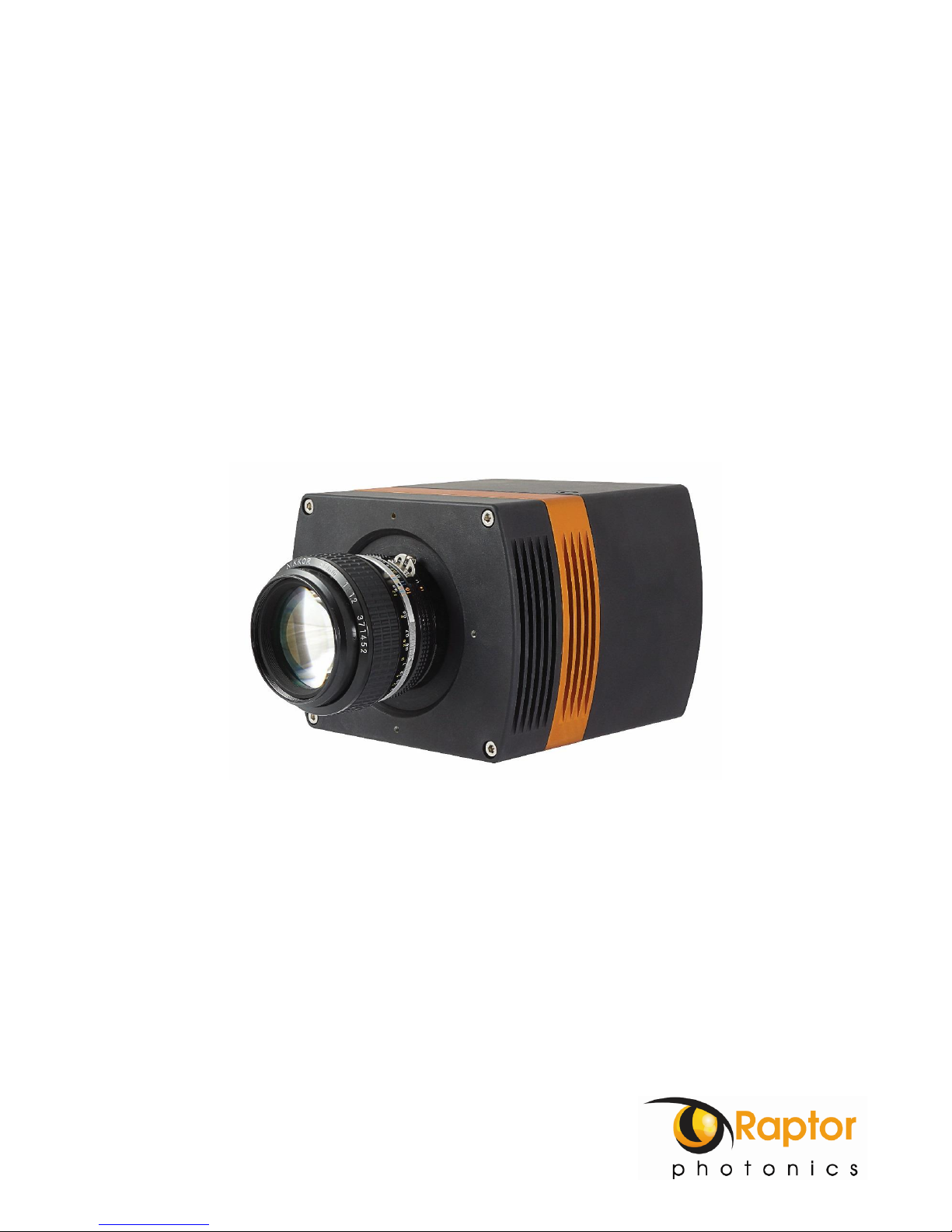
•Carefully thread the F-mount lens onto the camera’s lens ring until it is securely fastened. Use
the lens controls to adjust focus. We suggest that the camera be mounted on a tri-pod or an
optical bench.
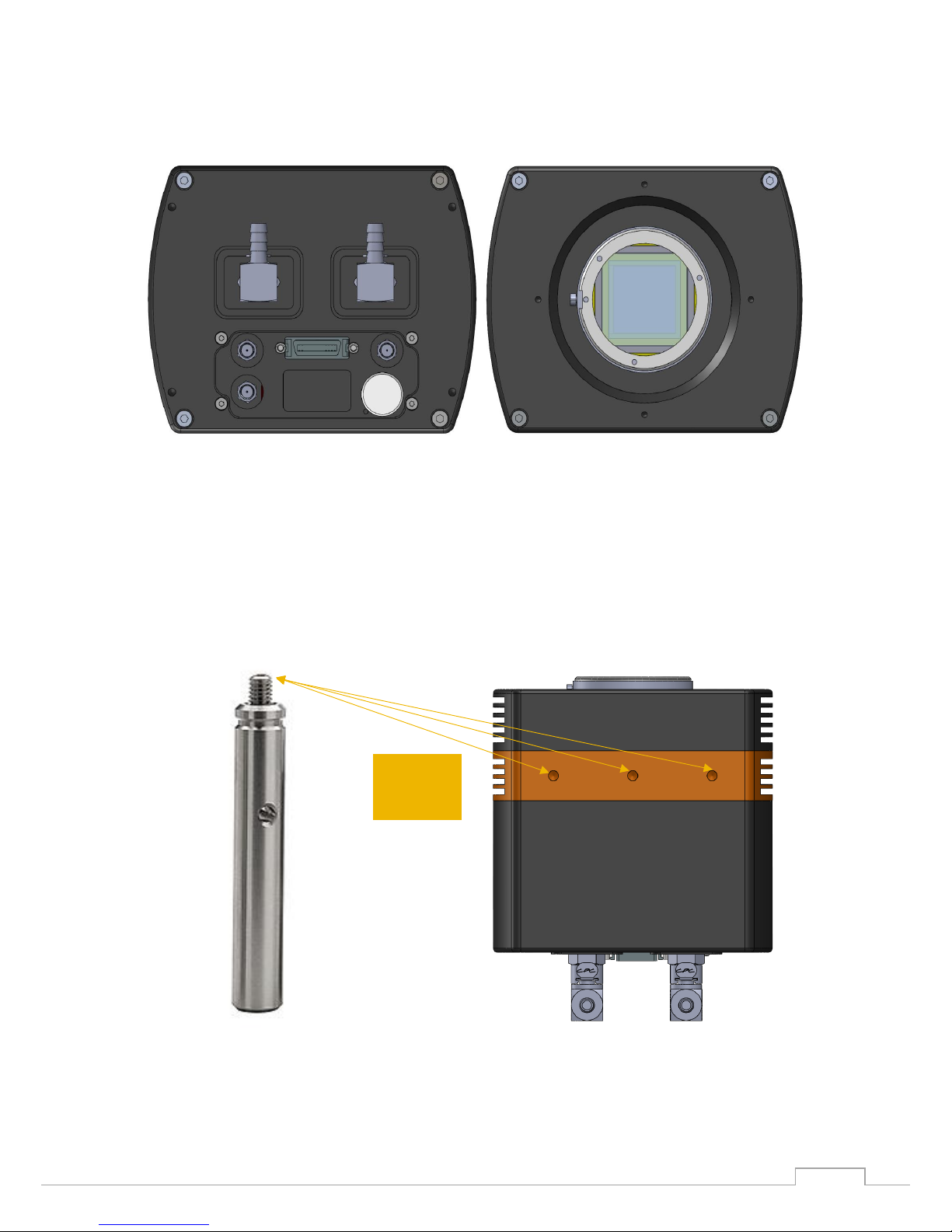
•The Eagle V has its own custom 12V power supply module and camera power cable. Connect a
mains lead to the power supply module and the power cable to the camera through the LIMO
connector. A red guide dot on the cable and camera highlights where to insert the connector.
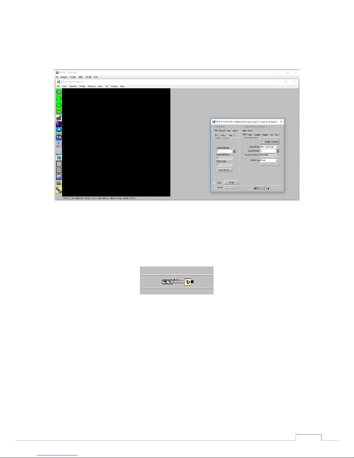
The Eagle V camera is compatible with all types of Camera Link frame grabber. However, our cameras
are extensively tested using Epix Inc. equipment’s XCAP, for this reason we recommend XCAP software.
XCAP
XCLIB
NI Labview
Micromanager
Hawk 252
Falcon II
Falcon III
Eagle
Owl 320
Owl 320 High Speed
Owl 'Mini'
Owl 640
Ninox 640
Owl 1280
- Software tested by Raptor Photonics
- Software tested by other companies
Blank - The camera has not been tested or is not supported by this software

EA4240-CL and EA4710-CL / USER MANUAL Rev1.3
February 2018
8
3.6 Using a liquid re-circulator.
The TEC and fan will allow the Eagle V to cool but if you want to run the camera at its optimum of -
95C, you will need to use a Liquid Re-circulator unit. This will help to remove the heat from the hot
side of the sensor. A typical set-up is shown in Figure 1.
Figure 1: Liquid re-circulator set-up
Please consult the Eagle V data sheet for a list of recommended re-circulators and tubing accessories
required. The set-up is as follows:
•Connect the cooling pipes and tubes to the camera and the pre-filled circulator.
•Switch on the circulator; you will now see bubbles traveling along the tubing.
•Wait for the bubbles to bleed into the reservoir, top up the reservoir as required. You should
tilt the camera side to side to ensure there are no bubbles remaining in the camera.
•Now adjust the Temperature set point on the circulator, for the Eagle V camera 20°C is
preferred.
•Please ensure the temperature set point of the re-circulator is above your ambient dew point.
Disassembly and draining
•Disconnect all the tubing from the camera and re-circulator.
•The camera and tubes should be drained by holding the adaptor with the tubing above the
camera, as per Figure 2.
Figure 2: Drain the camera after use (left) and drain tubes (right)

EA4240-CL and EA4710-CL / USER MANUAL Rev1.3
February 2018
9
4. EPIX XCAP
For minimum computer system requirements, please contact Epix for the latest information.
4.1 Download and Install XCAP
Using the following link, http://www.epixinc.com/support/files.php, please select the appropriate
version of XCAP for your computer. Please ensure you are downloading from the section labelled. Pre-
release version with support for the latest cameras and latest PIXCI® imaging boards. Open the
downloaded file when complete and follow the onscreen instructions. Be sure to accept the board
driver installation.
4.2 Operating your camera using XCAP.
1. Open XCAP from within your operating system enabling administrative privileges.
2. Select PIXCI dropdown menu and select PIXCI Open Close, Figure 3 should appear.
Figure 3: Open / Close
3. Select Close, and then Click on the Camera & Format button.
4. Using the dropdown menu scroll down and select Raptor Photonics Eagle V-from the list (Figure 4).
Selecting OK when done.
Figure 4: Camera Selection

EA4240-CL and EA4710-CL / USER MANUAL Rev1.3
February 2018
10
5. Select Open and the viewing and control screens, Figure 5, will now open. Two windows should open
(Figure 5), a viewing window (Left) and a control window (Right).
Figure 5: XCAP Camera Control Screen
6. The camera controls are pre-configured in EPIX.
7. The control window on the right should reflect your chosen camera. For example, for the Eagle V, it
should read - EPIX PIXCI E8DB: Raptor Photonics Eagle V. If not, you need to select a different camera.
8. Check that the camera is communicating, see animated icon (Figure 6) on bottom right of control
screen.
Figure 6: Active Communication
9. You are now configured and connected, ready to acquire an image.
10. Check the Serial Connect box (to establish serial communication to the camera). This should contain
a tick (as circled in Figure 7).
11. Check the live button (as circled in Figure 7).

EA4240-CL and EA4710-CL / USER MANUAL Rev1.3
February 2018
11
Figure 7: Image Capture
12. You should now see an image. On the bottom of the screen, you should see something similar to
the following: Frame: 0 Size: 2048 x 2048 Resize 3.4x3.4 Video: 0.4 fps Capture: 0.4 fps Display: 0.4fps.
Figure 8a: Live Image Capture Window

EA4240-CL and EA4710-CL / USER MANUAL Rev1.3
February 2018
12
To adjust the image to upright, go to Resolution tab on the left and select left B-T from the drop down
menu. Then click on buffer tab again.
Figure 8b: Adjusted Live Image Capture Window
Changing the settings on XCAP
You have the ability to change several settings to control the camera through the tabs in the control
window of the EPIX software.
4.4 TEC
Thermoelectric Cooling (TEC). Use this tab to set and read back the sensor temperature. To operate
the camera for long exposures you will need to adjust the temperature of the Eagle V to deep cooling
using a combination of the TEC and a water re-circulator. The camera is capable of cooling to -90C.
Ensure that the camera is connected to the circulator and that the temperature is set to 20°C. Make
sure to rock the camera to ensure that the coolant is flowing evenly through the camera with no air
bubbles.
Then click on the TEC tab. On the TE Cooler drop down, select Enabled, and then set the TEC to -90°C.
This will take several minutes for the camera to reach the temperature. Click on the update temp button
every few minutes to check on the sensor temperature.

EA4240-CL and EA4710-CL / USER MANUAL Rev1.3
February 2018
13
Figure 9: TEC Tab
4.5 Exposure
Click on the Gain Tab.
Figure 10: Gain Tab
There is an option for high preamp gain, which is already pre-selected, offering the lowest noise. If
you have a bright signal, then there is the option to deselect, offering more signal albeit with about x5
less counts.
You can also adjust the exposure from 0.023msec through to 2.77msec. You should adjust it to 300
msec. at the start while setting up.

EA4240-CL and EA4710-CL / USER MANUAL Rev1.3
February 2018
14
4.6 Shutter
Click on the shutter tab (as per Figure 11).
Figure 11 Shutter Tab
There are three options in the shutter control; closed, open or exposure. If you select exposure, you
have to determine the shutter close delay and shutter open delay. A good test set-up to begin with is
go to live, set exposure to 300msec and shutter control to exposure. Then set closed to 49.15 and
Open to 19.66 and set Read-out mode to Normal.
4.7 Trigger
Click on the trigger tab (as in Figure 12).
Figure 12: Trigger Tab

EA4240-CL and EA4710-CL / USER MANUAL Rev1.3
February 2018
15
Use this tab to select the Trigger Mode (Live –ITR, Live - FFR, External Triggered or Button Triggered).
If you select one of the triggered options, you then get a trigger polarity option (Falling edge or raising
edge). To acquire a single image you use the button trigger. Click on unlive and hit the reset button.
Then click on snap and then single exposure. You can save this fie and open later in a program such as
Image J.
You can operate the Eagle V at two speeds by adjusting the readout clock, either 2MHz or 75kHz.
There is also a readout mode where you can select Normal data or a Test Pattern option.
4.8 AOI
Click on the AOI tab (as in Figure 13). Use this tab to set the binning options, which are as follows:
1x1
2x2
2x1
4x1
8x1
16x1
32x1
1x2
4x4
2x4
4x2
8x2
16x2
32x2
1x4
8x8
2x8
4x8
8x4
16x4
32x4
1x18
16x16
2x16
4x16
8x16
16x8
32x8
1x16
32x32
2x32
4x32
8x32
16x32
32x16
You also have the option to choose an Area of Interest within the main active region of 2048 × 2048.
The user must ensure that X offset + ROI width is ≤ 2048 and similarly the Y offset + ROI height is ≤
2048. Also, AOI width and AOI height must be > 0. (See Figure 13a).
Figure 13a: AOI size and offset
In the example in Figure 13b we have chosen a point 200 left and 200 from the top. We have then
defined the AOI width as 512 and the height as 512.
AOI

EA4240-CL and EA4710-CL / USER MANUAL Rev1.3
February 2018
16
Figure 13b: AOI settings
You can see how the image have focused on this particular area of interest in Figure 13b.
Figure 13c: AOI Example Image

EA4240-CL and EA4710-CL / USER MANUAL Rev1.3
February 2018
17
4.10 Information
Click on the Info tab (show in Figure 14) to view the cameras manufacturer data, for example Build date
and serial number.
Figure 14: Information Tab
4.11 Adjusting the image display (With XCAP Std only)
The Viewing Pallet is not automatically adjusted in the XCAP software.
This needs manually configured to give the best display of the RAW image data from the camera.
1. Go to the Modify/Contrast Modification menu, Figure 21.
2. Select “Stretch Contrast, Histogram Percentile Endpoints” and “Preview” Figure 20: Stretch Contrast.
3. Adjust the “Low Percentile Endpoint” and “High Percentile Endpoint” to optimize the image display,
defaults should be acceptable for most applications.

EA4240-CL and EA4710-CL / USER MANUAL Rev1.3
February 2018
18
Figure 15: Contrast Modification
Figure 16: Stretch Contrast

EA4240-CL and EA4710-CL / USER MANUAL Rev1.3
February 2018
19
5. MICRO-MANAGER
Micro-Manager is software for control of microscopes. It works with almost all microscopes, cameras
and peripherals on the market, and provides an easy to use interface that lets you run your microscopy-
based experiments. Micro-Manager runs as a plugin to ImageJ, is Open Source, and is free.
It is a complete image acquisition and microscope control package, available for Windows, Mac and
Linux, it is easy to install and configure right "out-of-the-box", with built-in functionality and user
interface for most common tasks performed in a Life Science laboratory. It also is a software framework
for implementing advanced and novel imaging procedures, extending functionality, customization and
rapid development of specialized imaging applications.
Micro-Manager has been developed at UCSF since the beginning of the project. Starting on October 1,
2015, Micro-Manager is developed and maintained by Open Imaging, a company founded by the Micro-
Manager development team.
5.1 Download and install
Begin by installing the latest Micro-Manager. This can be done by going to the ‘downloads’ section of
their website: www.Micro-Manager.org.You should select the latest nightly build for your operating
system, found in the ‘Download Nightly Builds’section. This will open a direct link to the Micro Manger
FTP site where you can download most recently modified file.
Figure 17: Micro-Manager Nightly Builds

EA4240-CL and EA4710-CL / USER MANUAL Rev1.3
February 2018
20
5.2 Configuring Micro-Manager
When first opening Micro-Manager for the first time you will see the window shown in (figure 22). You
need to make sure (none) is selected then click Ok.
Figure 18: Hardware Configuration
1. Start the Hardware Configuration Wizard by going to tools then Hardware Configuration Wizard.
Figure 19: Hardware Configuration Wizard
This manual suits for next models
1
Table of contents
Other Raptor Digital Camera manuals