Raptor OWL 1280 User manual

OWL 1280
Model: OW1.7-VS-CL-1280
USER MANUAL

OW1.7-VS-CL-1280/ USER MANUAL REV1.1
November 2017
2
CONTENT
CONTENT................................................................................................................................................. 2
1. INTRODUCTION ........................................................................................................................... 3
2. SPECIFICATION ............................................................................................................................4
3. GETTING STARTED....................................................................................................................... 6
4. EPIX XCAP .................................................................................................................................... 9

OW1.7-VS-CL-1280/ USER MANUAL REV1.1
November 2017
3
1. INTRODUCTION
1.1 Scope
This manual covers the Owl 1280 digital camera and all applicable components. Raptor recommends
that this manual be used to optimize camera operation.
1.2 Camera Care
Raptor cameras require no regular maintenance except occasional external cleaning of the sensor
window (the glass window between the camera sensor and the microscope or lens). Should any other
issues occur please contact your local agent.
To clean the sensor window: gently wipe the face of the sensor window with a small amount of optical
grade isopropyl alcohol and lens paper. Apply forced air again to remove any loose particles.
CAUTION —The camera’s sensor, and circuits are sensitive to static discharge. Ensure you are using a
static strap or are completely grounded at all times to release any static energy before you clean the
window.
CAUTION —Do not use acetone.

OW1.7-VS-CL-1280/ USER MANUAL REV1.1
November 2017
4
2. SPECIFICATION
2.1 Camera Specification
The OWL 1280 digital camera is designed for high-resolution applications requiring visible to SWIR
imaging (400-1700nm). The OWL 1280 camera uses an InGaAS sensor with a resolution of 1280 x 1024
in a 12-bit digital output. High-speed low-noise electronics provide linear response and sensitivity for
rapid image capture.
The Camera Link digital interface provides the most stable platform for data transfer and the camera
will work on any Camera Link standard card.
A Software Development Kit (SDK) is available for interfacing with custom software.
FPA Specification
Sensor Type
InGaAs PIN-Photodiode
Active Pixel
1280 x 1024 / 640 x 512 (binning)
Pixel Pitch
10μm x 10μm / 20μm x 20μm (binning)
Active Area
12.8mm x 10.24mm
Spectral response1
0.4μm to 1.7μm
Noise (RMS)
<170 electrons Low Gain,
<35 electrons High Gain
Quantum Efficiency
Peak >92% (>87% @ 1.064nm, 82% @ 1.55nm)
Pixel Well Depth
Low Gain: 500Ke-
High Gain: 10Ke-
Pixel Operability
>99.5%
Digital Output Format
12 bit Camera Link (Medium Configuration)
Exposure time
1μs to 1 / frame rate
Shutter mode
Global shutter
Frame Rate
Up to 120Hz programmable, 25ns resolution
Optical Interface
C mount (selection of SWIR lens available) or M42
Camera Setup / Control
Camera Link
Dynamic Range
12 bit
Trigger interface
Trigger IN and OUT - TTL compatible
Power supply
12V DC ±10%
TE Cooling
ON / OFF
Image Correction
3 point NUC (offset, Gain & Dark Current) + pixel correction
Functions controlled by serial
communication
Exposure, intelligent AGC, Non Uniformity Correction,
Gamma, Pk/Av, TEC, ROI
Camera Power Consumption
< 3W (TEC OFF, NUC ON)
<5W (TEC ON in ambient, NUC ON)
Operating Case Temperature
-20°C to +55°C
Storage Temperature
-30°C to +60°C
Dimensions & Weight
50mm x 50mm x 61.2mmv / 247g
Latest version available on www.raptorphotonics.com

OW1.7-VS-CL-1280/ USER MANUAL REV1.1
November 2017
5
2.2 Mechanical Outline
3D drawings (STEP) are available upon request.

OW1.7-VS-CL-1280/ USER MANUAL REV1.1
November 2017
6
3. GETTING STARTED
3.1 System Overview
3.2 Mounting to Microscope
The OWL 640 has a standard C-Mount that should easily screw onto any microscope port.
3.3 Mounting to a tripod or optical table
The camera has a ¼-20 BSW (Whitworth), threaded hole to mount to a tripod or an optical table. The
image below shows an optical table mount with the ¼-20 BSW thread.
¼-20 BSW

OW1.7-VS-CL-1280/ USER MANUAL REV1.1
November 2017
7
3.4 3rd PARTY SOFTWARE
Raptor supports a range of 3rd party software packages as per the matrix below.
XCAP
XCLIB
NI
Labview
Micro-
Manager
StreamPix
Genika
Astro
Audela
Astro
Control
Kite
Hawk 247
Falcon II
Falcon III
Eagle
Owl 320
Owl 320 High Speed
Owl 'Mini'
Owl 640
Ninox 640
Owl 1280
In this guide, there is a quick overview of XCAP (http://www.epixinc.com/support/files.php) and Micro-
Manager (https://micro-manager.org). Should you have other software support specific needs, please
do not hesitate to contact our sales team on sales@www.raptorphotonics.com.
- Software tested by Raptor Photonics
- Software tested by other companies
Blank - The camera is not supported by this software

OW1.7-VS-CL-1280/ USER MANUAL REV1.1
November 2017
8
3.5 Connecting your camera to a computer
Boot up the computer.
Insert EPIX software key dongle into a USB port of your PC (the red light on the dongle should
light up).
Use the Camera Link cables to connect the camera to the computer. Where the cable closest
to the trigger and power connectors going to the port on the frame grabber closest to the
motherboard on the PC.
We advise using Camera Link cables of length 2m. When using cables of greater length than
this, the camera will not perform at its optimum level and will eventually not operate at all.
Carefully thread the C-mount lens onto the camera’s lens ring, rotating the lens in a clockwise
direction until it is securely fastened. Use the lens controls to adjust focus. We suggest that
the camera be mounted on a tri-pod or an optical bench.
Connect the 12V power supply to the camera.
The Owl 1280 camera is compatible with all types of Camera Link frame grabber. However, our cameras
are extensively tested using Epix Inc equipment’s XCAP, for this reason we recommend XCAP software.

OW1.7-VS-CL-1280/ USER MANUAL REV1.1
November 2017
9
4. EPIX XCAP
For minimum computer system requirements, please contact Epix for the latest information. It is a
minimum requirement to use a PIXCI E8 frame grabber. Bit packing must also be switched off in order
for the camera to image.
4.1 Download and Install XCAP
Using the following link, http://www.epixinc.com/support/files.php, please select the appropriate
version of XCAP for your computer. Please ensure you are downloading from the section labelled. Pre-
release version with support for the latest cameras and latest PIXCI® imaging boards. Open the
downloaded file when complete and follow the onscreen instructions. Be sure to accept the board
driver installation.
4.2 Operating your camera using XCAP.
1. Open XCAP from within your operating system enabling administrative privileges.
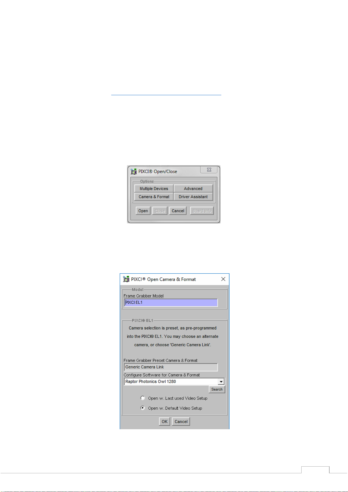
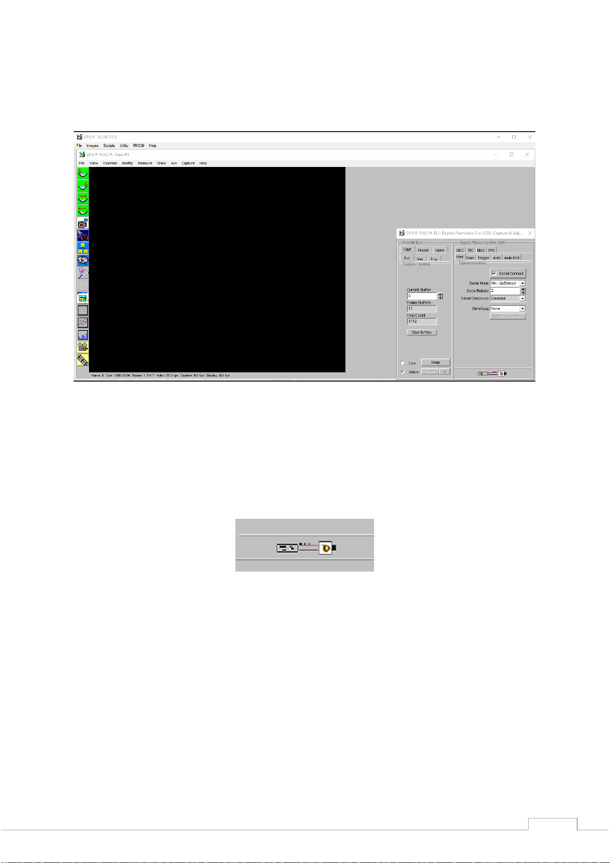
2. Select PIXCI dropdown menu and select PIXCI Open Close, Figure 1 should appear.
Figure 1: Open / Close
3. Select Close, and then Click on the Camera & Format button.
4. Using the dropdown menu scroll down and select Raptor Photonics OWL 1280 from the list (Figure
2). Selecting OK when done.
Figure 2: Camera Selection

OW1.7-VS-CL-1280/ USER MANUAL REV1.1
November 2017
10
5. Select Open and the viewing and control screens, Figure 3, will now open. Two windows should
open, a viewing window (Left) and a control window (Right).
Figure 3: XCAP Camera Control Screen
6. The camera controls are pre-configured in EPIX.
7. The control window on the right should reflect your chosen camera. For example, for the Owl 1280,
it should read - EPIX PIXCI EL1: Raptor Photonics OWL 1280. If not, you need to select a different
camera.
8. Check that the camera is communicating, see animated icon (Figure 4) on bottom right of control
screen.
Figure 4: Active Communication
9. You are now configured and connected, ready to acquire an image.
10. Check the Serial Connect box (to establish serial communication to the camera). This should contain
a tick (as circled in Figure 5).
11. Check the live button (as circled in Figure 5).

OW1.7-VS-CL-1280/ USER MANUAL REV1.1
November 2017
11
Figure 5: Image Capture
12. You should now see an image. On the bottom of the screen, you should see something similar to
the following: Frame: 0 Size: 1280x1024 Resize 1.7x1.7 Video: 25.0fps Capture: 25.0 fps Display: 25.0fps.
Figure 6: Live Image Capture Window

OW1.7-VS-CL-1280/ USER MANUAL REV1.1
November 2017
12
4.3 Changing the settings on XCAP
You have the ability to change several settings to control the camera through the tabs in the control
window of the EPIX software.
4.4 Exposure
Click on the Gain Tab.
There is an option for Auto Level Control (ALC). When Auto Level Control is unchecked, you can
manually adjust the exposure and digital gain using the sliders or entering a specific value in the field.
It is recommended to start with auto gain on to get an image, then turning it off to fine-tune your image.
Figure 7: Gain Tab

OW1.7-VS-CL-1280/ USER MANUAL REV1.1
November 2017
13
4.5 Trigger
Use this tab to select the Readout Mode, and a Fixed Frame Rate value.
Figure 8: Trigger Tab
4.6 Auto
On this Tab, you can select the parameters for the Automatic Level Control, Including the speed, and
spread of signal. In this mode, the FPGA of the camera will automatically adapt the exposure time and
digital gain within the given frame rate to optimise the image quality.
Figure 9: Auto Tab

OW1.7-VS-CL-1280/ USER MANUAL REV1.1
November 2017
14
4.7 Auto ROI
Use this tab to set the Region of Interest (ROI) used for the Auto Level Control; ROI gain will set an
overlay onto the image, so you can track its position. By default, this will be set to account for the
whole image. Edit the values of Offset, Width and Height to place the Auto Level Control ROI over the
image.
Figure 10: Auto ROI Tab
Figure 11: Active ROI Dark Area
In Figure 11, the ROI is contained within the small white box, and as such when centred on the black
case we can see the minor scratches but the sun light on the carpet has saturated the image.

OW1.7-VS-CL-1280/ USER MANUAL REV1.1
November 2017
15
Figure 12: Active ROI
However, when we move the ROI box to the carpet, Figure 12, where the sun is shining the camera
adjusts the exposure, but the box becomes too dark to see any detail. This is an extreme example used
with our Owl 640 camera to illustrate this feature.
4.8 NUC
On this tab, you can select the parameters for the on-board Non Uniformity Correction (NUC); select
the 3point NUC Offset, Gain & Dark shown in Figure 13. Figure 14 and Figure 15 show the effect of
the NUC off and on. When Normal is selected the NUC will be off
Figure 13: Controlling the NUC Status

OW1.7-VS-CL-1280/ USER MANUAL REV1.1
November 2017
16
Figure 14: NUC Off Figure 15: NUC On
4.9 TEC
Thermoelectric Cooling (TEC). Use this tab to set and read back the sensor temperature. The optimum
temperature should be set on start-up, for the OWL 1280 should be 15°C.
Figure 16: TEC Control

OW1.7-VS-CL-1280/ USER MANUAL REV1.1
November 2017
17
4.10 Miscellaneous
There are two features here, Video invert and Active Image Enhancement. Output video can be digitally
inverted such that dark areas in the image will appear bright by checking the video invert box.
Figure 17: Camera Information
Output video can be digitally processed to provide image sharpening by checking the Active image
enhancement box as shown in Figure 17.
The Info tab can be used to view the cameras manufacturer data, for example Build date and serial
number.
Figure 18: Information Tab

OW1.7-VS-CL-1280/ USER MANUAL REV1.1
November 2017
18
4.11 Adjusting the image display (With XCAP Std only)
The Viewing Pallet is not automatically adjusted in the XCAP software.
This needs manually Configured to give the best display of the RAW image data from the camera.
1. Go to the Modify/Contrast Modification menu, Figure 19.
2. Select “Stretch Contrast, Histogram Percentile Endpoints” and “Preview” Figure 20: Stretch Contrast.
3. Adjust the “Low Percentile Endpoint” and “High Percentile Endpoint” to optimize the image display,
defaults should be acceptable for most applications.
Figure 19: Contrast Modification
Figure 20: Stretch Contrast

OW1.7-VS-CL-1280/ USER MANUAL REV1.1
November 2017
19
CORPORATE HEADQUARTERS
Raptor Photonics LTD
Willowbank Business Park
Larne, Co Antrim
BT40 2SF
Northern Ireland
PH: +44 2828 270141
www.raptorphotonics.com
This manual suits for next models
1
Table of contents
Other Raptor Digital Camera manuals