Raritan 1700 Series User manual

ELECTRIC WATER HEATERS
With or Without Optional Heat Exchanger
INSTALLATION and MAINTENANCE INSTRUCTIONS
1700 Series Models
DESCRIPTION
Raritan Water Heaters are constructed with high quality components: a glass lined tank, high density
non-CFC foam insulation, noncorrosive polymer jacket and an adjustable Thermostat. Models with an
internal Heat Exchanger heat water from an external source. Dockside hot water recovery rate is 13 gallons
(49.2 liters) per hour. (18 gallons [68.1 liters] per hour for model #17120203 or 17200203 with 4500 watt/
240V heating element). Ground terminal and replaceable Anode are built in. Temperature and Pressure
Valve rated at 75 psi (517 kPa) 210°F (99°C) is included for on-board nominal working system pressure
of 50 psi (345 kPa) maximum. If working pressure is 60 psi (414 kPa) then a temperature and pressure
valve rated at 100 psi (790 kPa) is available (part WH3A). If operating pressure exceeds 60 psi (414 kPa)
then use a pressure reducing valve for entire plumbing on the boat. The water heater is ignition protected
as per United States Coast Guard regulation 33 CFR 183.410.
L206 0420 jlc
WARNING: Raritan Engineering Company, Inc. recommends that a qualied person or electrician install
and service this product. Equipment damage, injury to personnel or death could result from
improper installation. Raritan Engineering Company, Inc. accepts no responsibility or liability
for damage to equipment, injury to personnel or death that may result from improper installation
or operation of this product.
WARNING: Hazard of Shock or Fire - Always use recommended fuse/circuit breaker and wire size. Always
make sure that unit is properly grounded to AC grounding conductor (green). Do not use an
extension cord. Contact a qualied electrician to have wiring properly installed.
Hazard of Scalding - Water temperature over 125°F (52°C) can cause severe burns
instantly. Supervise children when using hot water. Water heaters equipped with engine
heat exchanger can heat water to very high temperature. Thermostatic mixing valve
should be installed before point of use to limit the water temperature to maximum
of 125° F (52° C). For more information, see your qualied technician.
WARNING: Hydrogen gas can be produced in a hot water system served by this heater that has not been used
for a long period of time (generally 2 weeks or more). Hydrogen gas is extremely ammable.
To reduce the risk of injury under these conditions, it is recommended that a hot water faucet be
opened for several minutes before using any electrical appliance connected to the hot water
system. If hydrogen is present, there will probably be an unusual sound such as air escaping
through the pipe as the water begins to ow. There should be no smoking or open ame near
the faucet when it is initially opened.
IMPORTANT SAFETY INSTRUCTIONS
1. Read all instructions thoroughly.
2. Install or locate water heater only in accordance with the provided installation instructions.
3. Use water heater only for its intended use as described in this manual.
4. Do not operate if wiring is damaged, or if the heater has been damaged or dropped.
5. Only qualied service personnel should service this water heater. Contact Raritan Technical Support
for repairs.

2
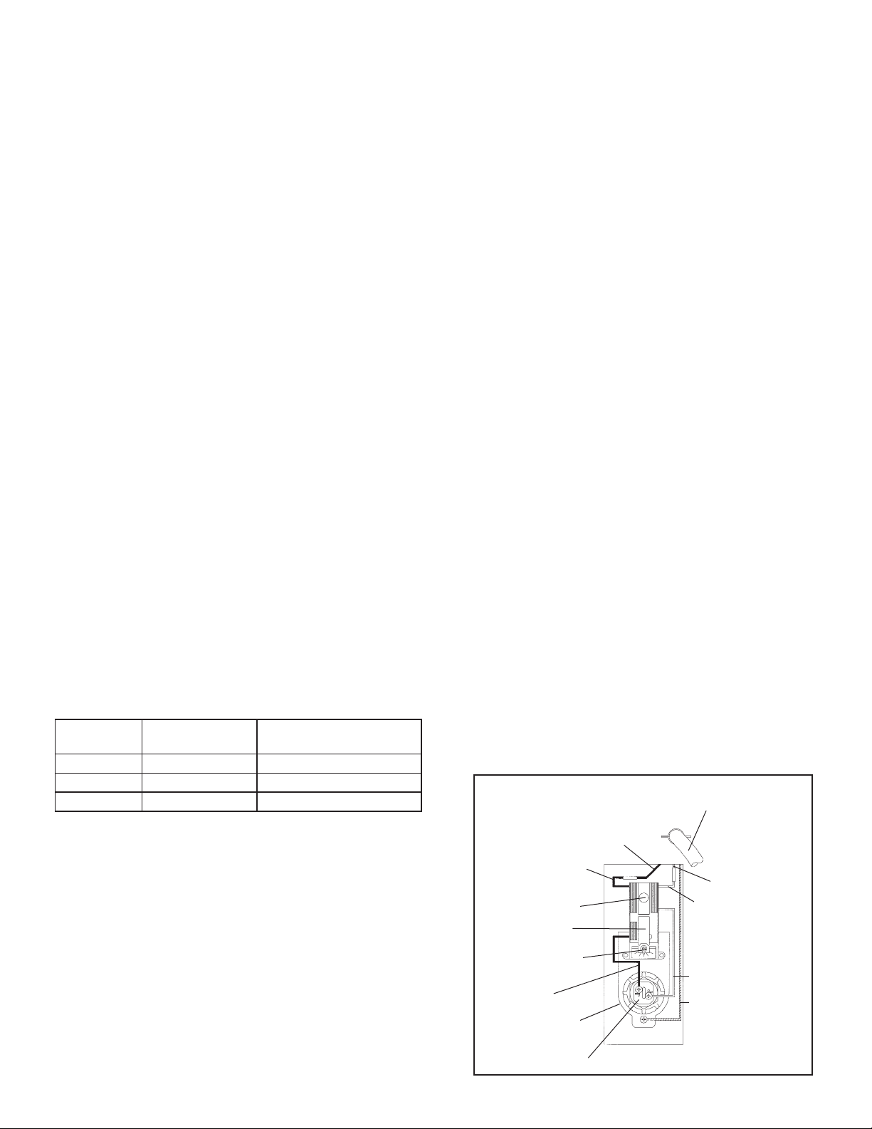
REPLACING THE THERMOSTAT
WARNING: Danger of shock. Be sure to turn power o.
Use ONLY Raritan replacement thermostat
(#WH16 ignition protected).
1. Remove access panel to thermostat and element.
2. Remove cover (personnel protector).
3. Unscrew the neutral and hot wires from the element with
a Phillips screw driver.
4. Cut the incoming wires. Pull tabs of thermostat mounting
bracket forward and lift thermostat out.
5. Install new thermostat.
6. Strip incoming wires, exposing 5/16" (8mm) of wire.
7. Crimp neutral wire supply to white wire and hot wire
supply to black wire (series connector provided with new
thermostat).
8. Screw ring terminals of white and black wires on lower
side of thermostat to studs of the element.
9. Reinstall personal protector panel.
NOTE: Check for leaks before proceeding.
10. Replace access panel.
11. Turn on AC power.
L206 0420jlc
2
FIG 1
MAINTENANCE
Following installation, temperature and pressure relief lever
MUST be operated by lifting lever up AT LEAST ONCE A
YEAR to ensure that the water ways are clear. Certain naturally
occurring mineral deposits may adhere to the valve, rendering
it unoperative. When manually lifting the lever up, water will
discharge and precautions must be taken to avoid contact with
hot water and to avoid water damage. BEFORE lifting lever
up, check to see that a discharge line is connected to this valve
directing the ow of hot water from the valve to a proper
place of disposal, otherwise personal injury from hot water
or steam may result. If no water ows, valve is inoperative.
TURN OFF THE WATER HEATER AND REPLACE THE
VALVE IMMEDIATELY.
If a backow preventer such as a check valve is installed in
cold water line and temperature and pressure valve discharges
a cup of water per 10 gallon capacity of water heater during
heating, reason for this occasional discharge is thermal
expansion of water in closed system. An expansion tank
should be installed in cold water line after check valve to
correct such occasional discharge or dripping of temperature
and pressure valve (See FIG 2).
Inspection of Anode and proper winterization is required
of the Raritan Water Heater. Periodic visual inspection is
recommended to be sure connections are tight, wires are
not frayed and the unit is properly grounded. DO NOT use
solvents to clean heater jacket. Incorporate this inspection
into commissioning procedure in spring and winterizing
procedure in fall.
A removable magnesium Anode is integral with the hot water
discharge tting. The Anode should be checked frequently
depending on hardness of water by removing it from the
water heater. Initially after installation, check within a year
and depending on water quality frequency can be reduced to
every 3 to 5 years. If the Anode diameter is less than 3/8"
(9.5 mm), it should be replaced. If discoloration, unusual
smell or taste develop in the water, inspect or replace Anode.
The Anode is replaceable as a unit and may be ordered from
Raritan dealers or from the factory. Please specify part number
1790610 for 6 gallon model and part number 1790010 for 12
and 20 gallon models.
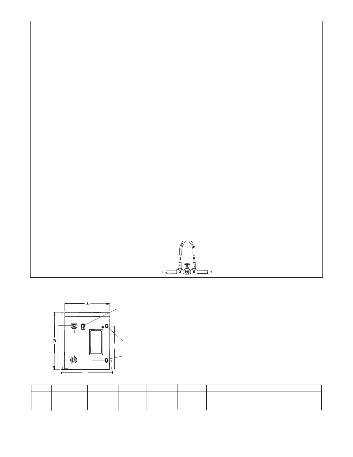
REPLACING THE ANODE IN RARITAN
WATER HEATERS
4. When water stops owing out, remove any piping or
ttings from hot water “out” nipple tting (see FIG 1).
5. Remove plastic nish washer to reveal unthreaded
area of nipple. Remove nipple with pipe wrench. Note
that magnesium rod extends well into water heater and
adequate clearance must be available to remove it.
11" for 6 gallon tanks and 16" for 12 and 20 gallon tanks.
6. Apply pipe PTFE thread compound or thread tape
to new anode and screw into water heater tank.
Tighten securely with pipe wrench. Re-connect all
external plumbing.
7. Close temperature and pressure relief valve and turn
on pressure pump.
8. When pump has come up to pressure and shut o,
check for leaks, then restore electric power.
1. Turn o electric power to water heater.
2. Turn o pressure pump and open faucets to bleed
pressure from water system. When water stops, close
faucets.
3. Open pressure and temperature relief valve to allow
water level in water heater to drop below level of
valve.
Plastic nish washer,
press this in to reveal
unthreaded portion of
nipple
TEMP./PRESS.
RELIEF VALVE
HOT
COLD
Unthreaded section
of anode nipple - grip
with pipe wrench to
remove and re-install
ANODE
Plastic nish washer.
Remove washer from
anode this will reveal
unthreaded portion of
nipple

3
WINTERIZING
Before beginning winterizing, be sure the power is turned
o to the water heater. Open all hot water taps on the boat
to relieve the pressure and allow cold water to cool the water
in the system. Remove both lines from the heater and allow
it to drain. After it has drained, blow it out with air pressure,
if available. Pour a quart of nontoxic antifreeze (propylene
glycol) into the hot water tting of the tank using a funnel and
short length of hose. Be sure power remains o until spring.
When recommissioning in the spring, run water long enough
to ensure that all antifreeze has been ushed out and tank is
lled BEFORE TURNING ON POWER. Heat exchangers are
winterized in conjunction with the boat’s engine cooling system.
INSTALLATION
Materials Required for Installation (not included with
water heater):
Plumbing: 3/4" NPT "Tee", check valve, expansion tank,
d r a i n v a lv e, P T F E t a p e , v a c u u m r e l i ef valve a nd s hut - o v a lv e.
For hot water connections use hose or plastic tubing rated for
hot water use. If system will be used with dockside water
supply, a pressure regulator valve, set to match boat pressure
system is also required. See FIG 2 for typical installation.
Electrical: Circuit breakers, stranded cable, wire crimp
terminals and wire supports/straps (See table 2 on page 5 for
breaker and wire sizes).
Hardware: Four 5/16" (8mm) stainless steel bolts or lag bolts,
at washers and hose clamps. For 12 and 20 gallon models:
stainless steel straps and fasteners.
Tools needed: Pipe wrench, screw driver, nut driver and
wrench(es) for mounting bolts or lag bolts.
MOUNTING THE HEATER
1. Select an area where the heater will not be subjected to
water spray (especially salt water).
NOTE: Access or hatch must be large enough for future
servicing and/or replacement.
2. Position heater so that electrical cover plates, plumbing
nipples and heat exchanger ttings are easily accessible.
3. Using the four mounting holes provided, securely mount
heater to deck or other sturdy at area. Stainless steel
5/16"(8mm) bolts or lag bolts with at washers should
be used to properly support the strain of a full unit while
the boat is rocking.
Raritan 12 gallon and 20 gallon water heaters require
auxiliary bracing, when the boat is in heavy seas. This is also
recommended for the 6 gallon models if excessive heeling and
pitching is expected. See FIG 4a (page 6) for optional bracing.
PLUMBING
CAUTION: To reduce the risk of excessive pressure and
temperature in this waterheater, temperature and pressure
sensitive protective equipment must be installed that meet
the requirement of local codes. A device MUST NOT be
installed unless it is certied by a nationally recognized
testing laboratory and meets the requirements for Relief
Valves and Automatic Shut-o Devices for Hot Water
Supply Systems, ANSI Z21.11-1979. The relief valve must
not be blocked or restricted under any circumstances.
For hot water connections use only piping, hoses, tubing,
xtures and connectors rated for hot water use.
Avoid sharp bends and 90° ells in the plumbing wherever
possible, as they reduce the water ow. Should copper
ttings be desired, DO NOT apply direct heat to the
3/4'' nipples protruding from the heater. They contain a
nonmetallic lining which will be destroyed by heat. Solder
ttings rst, then attach to water heater.
Refer to FIG 2 fortypical water heaterinstallation example.
1. Install Temperature and Pressure Relief Valve in area
marked "OPENING FOR TEMPERATURE AND
PRESSURE RELIEF DEVICE." Valve is included in
box separate from the heater. Use PTFE tape on
the threads.
WARNING: Discharge line shall be installed to allow
complete drainage of both the Temperature and Pressure
Relief Valve and discharge line.
3
WATER
TANK
CHECK
VALVE DRAIN
VALVE
WATER
HEATER
EXPANSION
TANK
MIXER
VALVE
TEMPERATURE &
PRESSURE RELIEF
VALVE
ACCUMULATOR
TANK (OPTIONAL)
PUMP
HEAT
EXCHANGER
IN
HEAT
EXCHANGER
OUT
HOT
COLD
HOT
COLD
SINKSINK
SHOWER
SEE WARNING FOR DISCHARGE
LINE IN PLUMBING SECTION
Typical Hookup for Water Pressure
System with Raritan Water Heater
FIG 2
L206 0420jlc

4
1. Remove access panel.
2. Strip outer insulation o the cable (long enough
for green ground wire to reach Grounding Screw)
exposing three insulated wires.
3. Loosen strain relief connector by turning
counterclockwise and insert cable. Then expose
approximately 5/16" (8mm) of bare wire on each
of the three pieces of stranded wire.
4. Grounding: Join the AC Grounding Conductor
(green), using the crimp-on terminal end (provided),
to the screw at the bottom of the Thermostat Bracket.
5. Attach black and white wires to Thermostat
per FIG 3. Use crimp-on terminal ends (provided)
to ensure a secure installation. Do not use solder
as it will cause the wire to become solid rather than
stranded (making it susceptible to breakage due to
vibration).
6. Tighten strain relief by turning it clockwise.
4
White
Black Service
Line (HOT)
Black Thermostat
Wire w/crimp
Connector
Red Reset Button
Continuous Ground
From Service Line
(Green)
White Service
Line (Neutral)
Thermostat Set
for 120o F (49°C)
Temperature
Adjustment
Black
Thermostat
Mounting Bracket
Connector
Service Lines By
Installer 120V AC
(or 240V AC)
Electric Screw-In Heating Element
White Thermostat
Wire w/crimp
FIG 3
Water heater
capacity
Expected thermal
expansion
Recommended minimum
expansions tank size
6 Gallons 11.6 oz 24 oz
12 Gallons 23.2 oz 24 oz
20 Gallons 38.6 oz ½ gallon or higher
Table 1
L206 0420jlc
WIRING
ELECTRICAL PREPARATION
All wiring should be done in accordance with ABYC E8,
AC wiring standard.
1. Install a 15 amp (10 amp for 240V AC or 20 amp for
model #17120203 and 17200203) Circuit Breaker in
the 120V AC service line to the water heater.
2. Use ONLY STRANDED #12-3 (#10-3 for model
#17120203 and 17200203) cable to the heater. NEVER
use solid (ROMEX-type) wire on a boat; vessel vibration
causes breakage due to metal fatigue (see U.S. Coast
Guard CFR Title 33, Part 183.423).
3. Secure wire at intervals of 18" (45.7cm). Allow about
24'' (61cm) of extra wire to make necessary connections.
4. An expansion tank of proper capacity (see Table 1)
should be installed in the cold water line to avoid
pressure buildup due to thermal expansion of water
(See FIG 2 on page 3).
2. The discharge line must pitch downward from the
valve and terminate with a 6" (152 mm) air gap
above the maximum bilge water level. Excessive
length, more than 30 feet (9.14 m), use of more
than four elbows or bend in discharge piping,
a reduction of discharge line size will cause
a restriction and reduce discharge capacity of
relief valve. NO shuto valve shall be installed
between the relief valve and water heater tank or
in discharge line.
NOTE: Discharge line from relief valve can be
discharged overboard if above requirements
are met.
3. If there is a shore connection inlet and if discharge
of temperature and pressure relief valve is not
connected overboard as per # 2 above, the relief
valve plumbing shall discharge into the bilge
above the normal accumulation of bilge water,
and a bilge high water alarm shall be installed per
ABYC H-22, Electric Bilge Pump Systems.
WARNING: HAZARD OF FLOODING:
If water heater is supplied by dockside (shore) water
connection, then do not leave water heaterunattended
as a failure in temperature and pressure relief valve
can ood the boat. Shut o dock side connection
while leaving boat unattended.
6. Secure all lines to the boat’s structure at frequent
intervals.
7. For models with heat exchangers see FIG 5 on
page 7
WARNING: Before working on unit, be sure that
the circuit breaker is o.
5. Thermostatic mixing valve should be
installed before point of use to limit the water
temperature to maximum of 125° F (52° C). For
more information, see your qualied technician.

5
TROUBLESHOOTING
WARNING: If temperature and safety valve is leaking it must be replaced.
Reference: www.raritaneng.com/tech support/repair shop
PROBLEM CAUSE CORRECTION
A. Water does not get
hot.
B. Relief valve opens
and releases hot
water.
C. Constant drip-
ping of relief
valve.
A1. No power at the heater.
A2. Malfunctioning heating
element or thermostat.
B1. Malfunctioning thermostat.
B2. If heat exchanger is in use,
the engine operating tem-
perature may be too high.
B3. Higher range relief valve may
be needed if pressure system
is near 60 psi
C1. Foreign matter lodged in the
seat of the relief valve.
C2. Check valve installed
incorrectly in cold water line.
C3. Higher range relief valve
may be needed if pressure
system is near 60 psi
5
CAUTION: To prevent burnout of heating
element do not turn on electricity. Follow start-up
procedure.
START - UP
1. After all plumbing lines have been properly installed and secured, open all hot water taps and turn on the
water pressure system.
2. Allow water to run a few minutes until all air is expeled and all outlets ow clear of air. Failure to expel air may cause
an air pocket in the tank. This will cause the heating element to burn out, as it will not be in contact with water. All the
air may not be expelled after purge, however over a period of time (two weeks) the remaining air in the tank will be
absorbed by the water.
3. Check for leaks.
4. Replace electrical access cover and turn on power.
Model
(Gallons)
Voltage and
Wattage
Circuit
Breaker Wire Size
6, 12, 20 120 V / 1250 W 15 Amps #12-3 Stranded Cable
6, 12, 20 240 V / 1250 W 10 Amps #12-3 Stranded Cable
12, 20 240 V / 4500 W 20 Amps #10-3 Stranded Cable
Table 2
L206 0420jlc
WARNING: Be sure power is o before start-up
procedure is performed.
A1. Be sure circuit breaker or switch is turned on and wiring
is not broken or disconnected.
A2. Check red reset button. Remove electrical access cover.
If red reset button has popped out, it must be reset by
depressing it, to restore power. If water is not warm
within 30 minutes check to be sure there is power at the
thermostat. This can be done by checking voltage at the
top of the thermostat, between the two top wires (on left
and right side of thermostat). If system voltage is pres-
ent, check for power at the heating element. If power is
available at heating element, heating element is burned
out. If power is not available at heating element, replace
thermostat.
B1. Check thermostat operation and replace it if bad. Use
qualied electrician if you cannot determine whether or
not thermostat is operational.
B2. If heater is equipped with a heat exchanger, and the relief
valve opens while engine is running, check your setting
and installation per Fig.#5.
B3. Replace Pressure Relief Valve (part# WH3A).
C1. Replace relief valve.
C2. Check valve does not allow for the thermal
expansion of water. Re-plumb per Fig. #2 using
expansion tank.
C3. Replace Pressure Relief Valve (part# WH3A)

6
FIG 4b
FIG 4a SUPPORT BRACKET OPTION FOR 12 and 20 GALLON WATER HEATER
Materials: 1" (2.5cm) full cut wood for (4) sides of frame; top is made of 3/4" (1.9cm) marine plywood.
All parts are screwed together.
PART NUMBERS
WH1A-S* Heating Element, 120V (screw-in) with gasket
WH1B-S* Heating Element, 240V (screw-in) with gasket
WH1D-S Heating Element, 4500 watt/240V (screw-in)
with Gasket
WH1GS Heating Element Gasket
WH3* Temperature and Pressure Relief Valve, 75 PSI
WH3A* Temperature and Pressure Relief Valve, 100 PSI
WH16* Thermostat
1790610 Anode 6 gallon
1790010 Anode 12 and 20 gallon
* Parts may be ordered at www.raritaneng.com.
SERVICE AND REPLACEMENT PARTS
Replacement parts may be ordered through your local
Raritan dealer or directly from the factory. Some
parts may be ordered at www.raritaneng.com. When
ordering please state part number, description and
quantity required. With some parts you may need
to know voltage. Questions or problems may be
referred to Raritan's Technical Support.
6
3/4"(1.9cm)
Marine Plywood
24"
(61cm)
Cut along this line to make
2 side pieces
20 3/4"
(52.7cm)
20 3/4"
(52.7cm)
8"
(20.3cm)
1" (2.5cm)
Full
18 3/4"
(47.6cm)
9"
(22.9 cm)
13/16" (22mm)
HOLE IN
CENTER
3/4" 10 UNC STUD, NUT
AND FLAT WASHER
SEE FIG. #3b
18 3/4"
(47.6cm)
1" (2.5cm)
Full 1" (2.5cm)
Full
1"
(2.5cm)
Full
1" (2.5cm)
Full
REMOVABLE PLUG
IN LID OF HEATER
3/4"(1.9cm) THICK TOP OF
FRAME
(MARINE PLYWOOD)
3/4" 10 UNC NUT WELDED
TO TANK
FOAM INSULATION
TOP OF TANK
PLASTIC HEATER LID
3/4" 10 UNC STUD
3/4" 10 UNC NUT
3/4" FLAT WASHER
3/4" FLAT WASHER
(as needed)
L206 0420jlc

7
HEAT EXCHANGER
The following information is only a general guideline and any installation is made at the risk of the
installer. No responsibility to Raritan Engineering Company, Inc. is to be presumed or implied from
these general instructions.
Two 3/4" NPT female threads are provided in the
heat exchanger for connection to hoses or pip-
ing from engine cooling system. Because of the
diversity of marine cooling congurations, it is
not possible to provide universal installation in-
structions; the installer MUST follow the engine
manufacturer's recommendations.
NOTE: If heat exchanger is higher than engine
coolant pump, check with engine manufacturer
for allowable height of coolant lines.
THE FOLLOWING DIAGRAM IS INTENDED ONLY AS A GENERAL GUIDELINE TO
SHOW HOWAPORTION OF THE ENGINE COOLANT MAY BE DIVERTED TO THE HEAT
EXCHANGER:
LEGEND:
1. Hottest water from engine (full ow).
2. Pipe tee; full ow on run, 3/4" NPT on branch.
3. Hose to hot water heat exchanger.
4. Gate valve sized to permit full ow of coolant.
5. Pipe tee; full ow on run, 3/4" NPT on branch.
6. Hose from hot water heat exchanger.
7. Full ow return to engine cooling system.
FROM WATER HEATER
(See Fig. #1)
TO WATER HEATER
To determine the proper setting of the gate valve
(4), the engine should be operated at full throttle
with the gate valve wide open. When the engine
temperature has stabilized, gradually close the valve
until the engine temperature begins to rise. The
valve should then be reopened enough to establish
the proper engine operating temperature. Engine
temperature should be monitored to verify that the
entire cooling system is functioning properly. Open
valve (4) if heated water temperature exceeds 120°
F (49°C).
WARNING: Piping and gate valve
(Item #4) may become extremely
hot while engine is operating. Be
sure to wear heavy gloves when
adjusting gate valve.
SPECIFICATIONS
Electrical Recovery Rate = 13 gallons (49.2 liters) per hour
Maximum Operating Pressure: Tank: rated at 150 psi (1034kPa)
WithTemperature and PressureValve Installed: 50 psi (345kPa)
Amps: 10 (120V AC), 5 (240V AC) or 18.75 (240V AC) for
model 17120203 and 17200203
Thermostat: Adjustable: Factory Set to 120°F (49°C)
(Eects AC Power only)
Anode: Magnesium
Model #
1706XX
1712XX
1720XX
Size Capacity A & B C D E F G Ship Wt.
6-gal(22.71liters) 6 gallons see above 3 3/8"(8.6cm) 11"(28cm) 10 ¼"(26cm) 12 1/2"(31.8cm) 16 ½"(42cm) 37lbs(16.8kg)
12-gal(45.4 liters) 11 gallons 3 3/8"(8.6cm) 11"(28cm) 10 ¼"(26cm) 12 3/8"(31.4cm) 20 ½"(52cm) 55lbs(24.9kg)
20-gal(75.7 liters) 17.5 gallons 3 3/8"(8.6cm) 18 ¾"(47.6cm) 10 ¼"(26cm) 12 3/8"(31.4cm) 20 ½"(52cm) 68lbs(30.8kg)
FIG 5
Note: 12 gallon with HE is 10 gallon capacity
XX = 01(120V) or 02(240V) without Heat Exchanger, 11(120V) or 12(240V) with Heat Exchanger
7
WARNING: If coolant water from engine is salt water, Heat Exchanger must stay ooded with water at all
times. Cycling between dry and full will corrode heat exchanger and void warranty.
Engine
Coolant Out
Engine
Coolant In
Cold Water
In
Hot Water
Temperature and
Pressure Valve Drain
to Bilge
E
C
D
F
G
C
6 gallon - 14 ½"(36.9cm)
12 & 20 gallon - 18 ¾"(47.6cm)
6 & 12 gallon:
16 ¼"(41.3cm)
20 gallon:
24 ¼"(61.6cm)
L206 0420jlc

8
Specications subject to change without notice. Printed in USA
LIMITED WARRANTY
Raritan Engineering Company warrants to the original purchaser that this product is free of defects in
materials or workmanship from the product’s date of purchase and should this product prove defective
by reason of improper workmanship and/or materials, Raritan shall, at its sole option, repair or replace
the product. For a period of ve years from the date of purchase, Raritan warrants the inner tank against
leaks provided the anode in the hot water outlet is checked annually. Raritan warrants all other parts for
a two year period.
1. TO OBTAIN WARRANTY SERVICE, Consumer must deliver the product prepaid, together with a
detailed description of the problem, to Raritan at 530 Orange St., Millville, N.J. 08332. When requesting
warranty service, purchaser must present a sales slip or other document which establishes proof of purchase.
THE RETURN OF THE OWNER REGISTRATION CARD IS NOT A CONDITION PRECEDENT OF
WARRANTY COVERAGE. However, please complete and return the owner Registration Card so that
Raritan can contact you should a question of safety arise which could aect you.
2. THIS WARRANTY DOES NOT COVER defects caused by modications, alterations, repairs or
service of this product by anyone other than Raritan; defects in materials or workmanship supplied by
others in the process of installation of this product; defects caused by installation of this product other
than in accordance with the manufacturer’s recommended installation instructions or standard industry
procedures; physical abuse to, or misuse of, this product. This warranty also does not cover damages to
equipment caused by re, ood, external water, excessive corrosion or Act of God.
3. ANY EXPRESS WARRANTY NOT PROVIDED HEREIN, AND ANY REMEDY FOR BREACH
OF CONTRACT WHICH BUT FOR THIS PROVISION MIGHT ARISE BY IMPLICATION OR OP-
ERATION OF LAW, IS HEREBY EXCLUDED AND DISCLAIMED. ALL IMPLIED WARRANTIES
SUCH AS THOSE OF MERCHANTABILITY AND OF FITNESS FOR A PARTICULAR PURPOSE, IF
APPLICABLE, AS WELL AS ANY IMPLIED WARRANTIES WHICH MIGHT ARISE BY IMPLICA-
TION OF LAW, ARE EXPRESSLY LIMITED TO A TERM OF TWO YEARS. SOME STATES DO
NOT ALLOW LIMITATIONS ON HOW LONG A LIMITED WARRANTY LASTS, SO THE ABOVE
LIMITATION MAY NOT APPLY TO YOU.
4. UNDER NO CIRCUMSTANCES SHALL RARITAN BE LIABLE TO PURCHASER OR ANY
OTHER PERSONS FOR ANY SPECIAL OR CONSEQUENTIAL DAMAGES, WHETHER ARISING
OUT OF BREACH OF WARRANTY, BREACH OF CONTRACT, OR OTHERWISE. SOME STATES
DO NOT ALLOW THE EXCLUSION OR LIMITATION OF INCIDENTAL OR CONSEQUENTIAL
DAMAGES, SO THE ABOVE LIMITATION OR EXCLUSION MAY NOT APPLY TO YOU.
5. No other person or entity is authorized to make any express warranty, promise or armation of fact
or to assume any other liability on behalf of Raritan in connection with its products except as specically
set forth in this warranty.
6. This warranty gives you specic legal rights, and you may also have other rights which vary from
state to state.
8
530 Orange Street
Millville, NJ 08332 USA
Telephone: 856-825-4900
FAX: 856-825-4409
www.raritaneng.com
L206 0420jlc
Table of contents
Other Raritan Water Heater manuals
Popular Water Heater manuals by other brands

REVENTON
REVENTON FARMER HCF IP66 Technical documentation

A.O. Smith
A.O. Smith HSE-SDS 6 user guide

PVI
PVI PV 413A Start-up instructions

State Water Heaters
State Water Heaters GS6 40 YBVIS Installation and operating manual

Kenmore
Kenmore 153.339372 owner's manual

Bradford White
Bradford White 238-46392-00G Installation & operating manual

TERMOMEX
TERMOMEX UKTER-11 Installation and operation manual

Rheem
Rheem GT-199PV Specification sheet

Heatrae Sadia
Heatrae Sadia ELECTROMAX SOLAR Installation & servicing instructions

Worcester
Worcester WR 325 BF Installation and servicing instructions

Sime
Sime MINI 16 BF ErP user manual

A.O. Smith
A.O. Smith CYCLONE Xi BTH 400A Installation & operating instructions