2
OPERATION
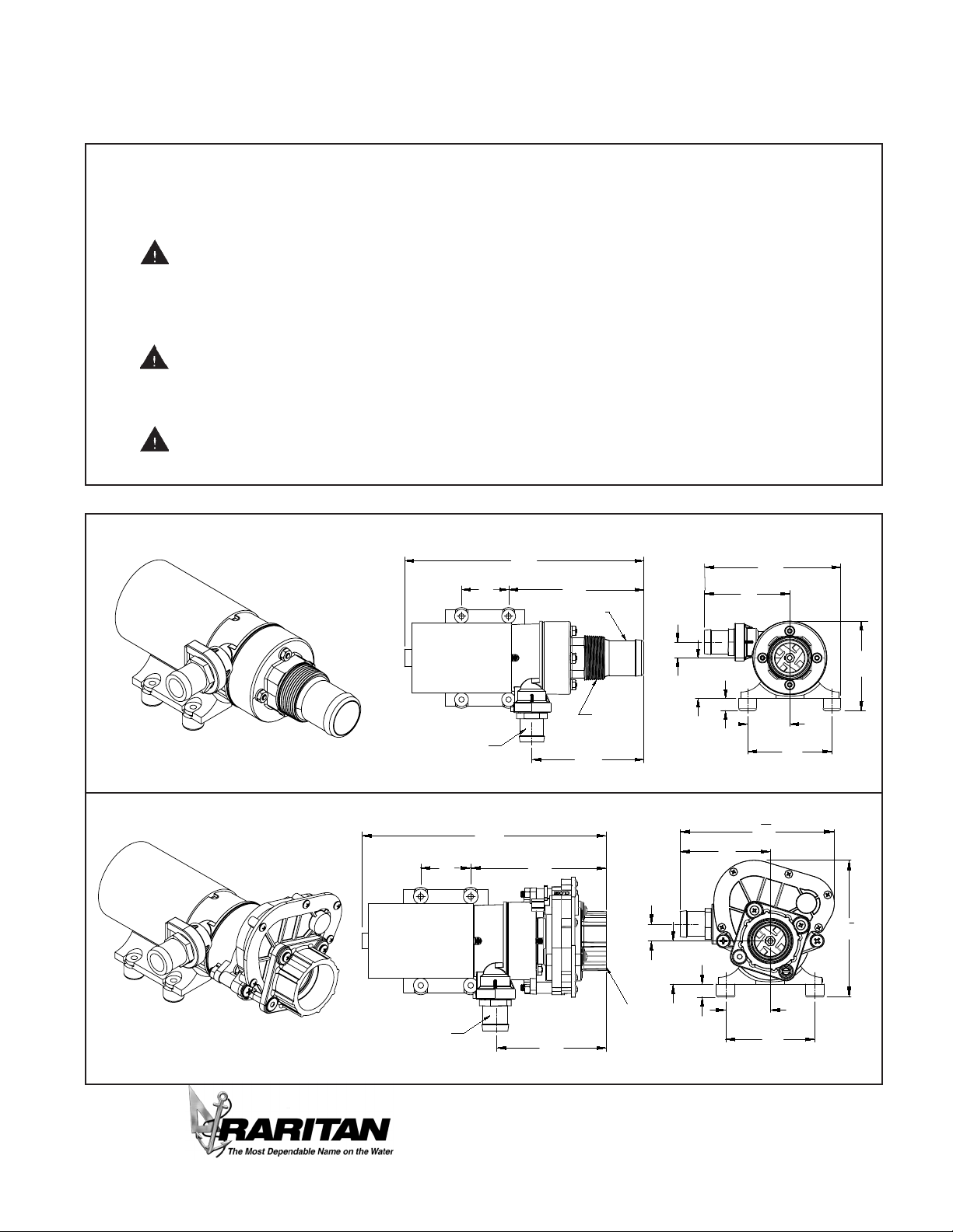
Designed to empty marine and RV holding
tanks of normal waste and sh boxes of scales
and residual waste. The unique dual-cut blade
design ensures waste is ground up thoroughly.
Marine pump out must be in proper discharge
zones only. This macerator will not handle hard
objects, rags, or feminine napkins.
e optional Smart Macerator Control (SMC)
monitors pump motor and prevents pump
damage due to priming failure or dry running.
It also protects motor against overload. If power
to control is not turned o, smart control will
prevent impeller sticking by jogging impeller
once every seven days of non- use.
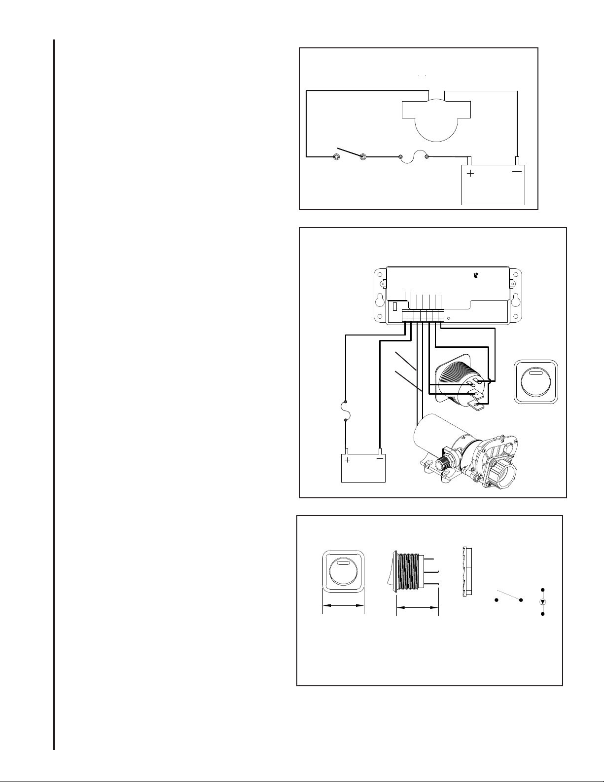
PUMP IS INTERMITTENT DUTY ONLY!
• Make sure Waste valve to pump and discharge
valve [if equipped] are both open. Turn on
momentary switch and pump out tank.
• When tank is empty, pump will get louder
with a high pitch sound. Immediately turn
pump o, or damage to impeller and housing
will occur. If pump is equipped with SMC,
pump will turn o after 5 seconds of dry
running
• If not equipped with SMC, do not run pump
dry for more than 15 – 20 seconds. Flush
tank and pump with water after each use.
This macerator will handle normal waste,
tissues, cigarettes, sh scales, etc. It is not
designed to handle large hard objects such as
large bones or fruit pits.
Periodic Maintenance and Storage: Flush
with water after each use. Check wire connec-
tions occasionally. After periods of non-use,
impeller can stick. To loosen, open rear shaft
cover and turn motor shaft clockwise with a at
tip screwdriver. Then replace shaft cover. For
extended periods of non-use, pump impeller can
be lubricated by running a small amount of min-
eral oil through holding tank system.
Maintenance: Turn o all power!
Rear end cap/ motor shaft slot access:
Remove cap over the shaft
Smart Macerator Control (SMC) (optional)
SMC monitors motor and pump to prevent dry
run and overload.
Turn on switch (ESR03A) to activate Macerator
Pump.
SMC control has following features:
1. If pump does not prime within 7 seconds,
SMC control will shut down the pump.
2. If pumps runs dry for 5 seconds, SMC
control will shut down the pump.
3. If pump draws more than 20 amps, control
will shut down pump.
4. LED at the switch and on the board will ash
if there is shut down due to priming failure
or dry run. LED will stay on if shutdown is
due to overload. SMC control can be reset
by turning o and on switch. Power need
not be turned o.
5. If power is not turned o to the control,
control will jog macerator pump for few
milliseconds every seven days if non use to
prevent binding of impeller.
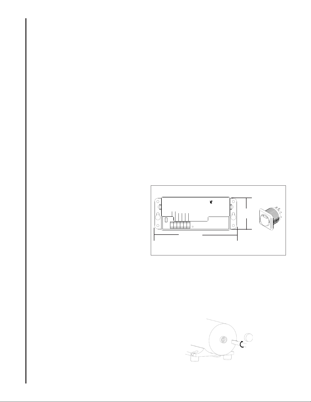
A Maintenance Tip!
Loosen stuck impeller by turning motor sha
clockwise from rear with a at-tipped screwdriver.
2
NOTE: This jog feature will function when switch
is in the OFF position.
Smart Macerator Control (optional)
Switch dimensions
Fig. 7 pg. 4
Inches [MM]
6 3/16" [157]
1 5/8"
[41]
Depth: 1 5/8" [41]
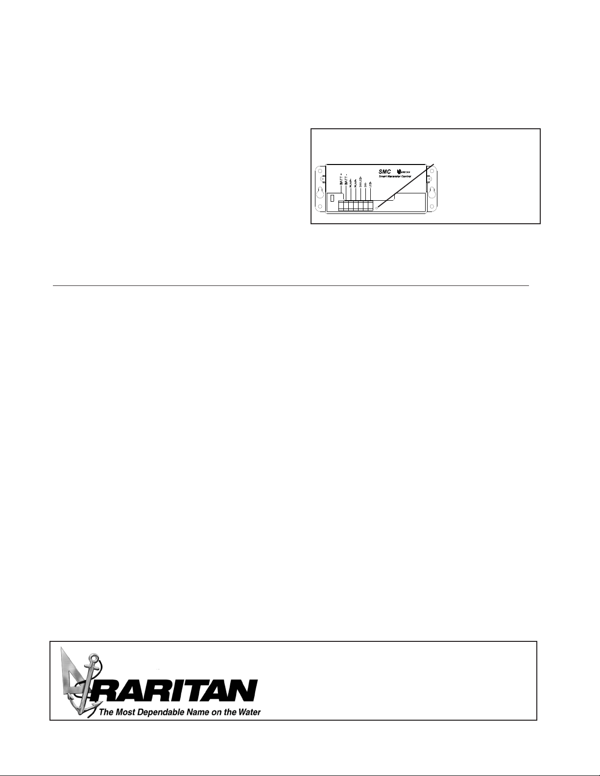
BATT -
BATT +
RARITAN
SMC
SW-
SW+
PUMP-
PUMP+
Smart Macerator Control