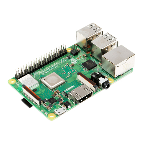
Raspberry Pi PiCoolFAN4 User manual

PiCoolFAN4 Firmware Code 0x14 Print Date 10.11.2019
Designed by www.pimodules.com manufactured in co-operation with www.thepihut.com
PiCoolFan 4
Advanced Active Raspberry Pi® Cooling System
with Hardware RTC
user LEDs, Sounder, Relay, IR and 1-wire interface
User Guide
Designed for the Raspberry Pi® 4 Model B
Compatible with
All former models of Raspberry Pi®
“Raspberry Pi” is a trademark of the Raspberry Pi® Foundation

PiCoolFAN4 Firmware Code 0x14 Print Date 10.11.2019
Designed by www.pimodules.com manufactured in co-operation with www.thepihut.com
Contents
SYSTEM OVERVIEW ...............................................................................................................................................3
INTRODUCTION..............................................................................................................................................................3
PICOOLFAN 4PCB LAYOUT ............................................................................................................................................4
SET UP PROCEDURE ...............................................................................................................................................5
WHAT’S IN THE BAG? .....................................................................................................................................................5
KIT ASSEMBLY ...............................................................................................................................................................6
USING A HEATSINK .........................................................................................................................................................8
BASIC FUNCTIONALITY...........................................................................................................................................9
FACTORY DEFAULTS........................................................................................................................................................9
IDENTIFYING THE CURRENT SETUP ...................................................................................................................................10
TUNING THE FACTORY DEFAULT TEMPERATURE THRESHOLD.................................................................................................11
ADVANCED FUNCTIONALITY ................................................................................................................................ 13
COOLING PROFILES.......................................................................................................................................................13
COOLING PROFILE PARAMETERS......................................................................................................................................14
HOW TO SET A COOLING PROFILE &PARAMETERS..............................................................................................................17
USING THE RASPBERRY PI TEMPERATURE SENSOR ..............................................................................................................18
LOW NOISE FAN COOLING TECHNIQUES ...........................................................................................................................20
I2C ADDRESS TABLE .....................................................................................................................................................21
ADDITIONAL FEATURE SETUP ..............................................................................................................................22
HW REAL TIME CLOCK..................................................................................................................................................22
SOUND GENERATION SYSTEM.........................................................................................................................................25
HIGH CURRENT RELAY...................................................................................................................................................26
USER LEDS.................................................................................................................................................................27
INFRA-RED RECEIVER INTERFACE.....................................................................................................................................28
ESD PROTECTED 1-WIRE INTERFACE ................................................................................................................................28
BOOTLOADER RESET PINS (4-PIN HEADER)........................................................................................................................28
SETTING FACTORY DEFAULTS............................................................................................................................... 29
BOOTLOADER OPERATIONS................................................................................................................................. 30
USING DIFFERENT I2C ADDRESS........................................................................................................................... 33
COMMON PROBLEMS & SOLUTIONS ................................................................................................................... 34
DOCUMENT REVISIONS........................................................................................................................................ 36
FIRMWARE REVISIONS.........................................................................................................................................36

PiCoolFAN4 Firmware Code 0x14 Print Date 10.11.2019
Designed by www.pimodules.com manufactured in co-operation with www.thepihut.com
System Overview
Introduction
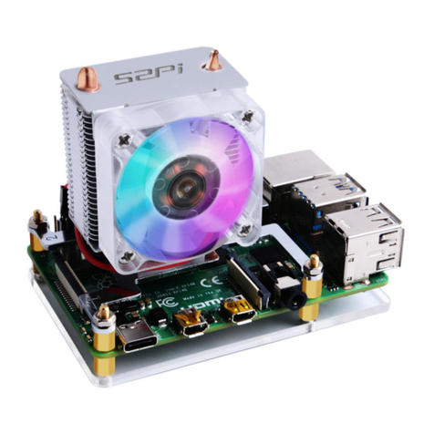
The PiCoolFAN4 is an Advanced Active Cooling System designed for the Raspberry Pi 4 as an independent
and autonomous cooling system, and can be used with all models of Raspberry Pi.
The PiCoolFAN4 provides an enhanced cooling capability using an embedded fan and temperature sensor.
The PiCoolFAN4 temperature sensor is placed exactly 3.5 mm above the Raspberry Pi 4 CPU. This
guarantees accuracy and continuity, measuring the system temperature as close to the CPU environment
as possible.
The PiCoolFAN4 does not need any software installation (great for software such as KODI, which can also
make use of the IR interface) and requires simple assembly by the user. If required, users can make use of
the provided software to enable greater control of the fan and cooling profile –including noise reduction.
The provided software allows the user to select either the Raspberry Pi’s CPU temperature for fan
threshold control, or the included temperature sensor on the PiCoolFAN4 PCB. In addition to this, the
software also allows the user to select and edit different cooling profiles which allow either instant fan
changes (‘hard’ cooling) or gradual changes in speed in-line with temperature changes (‘mild’ cooling).
The PiCoolFAN4 does not use any GPIO pins - all communication with the Raspberry Pi is via I2C. This
leaves your GPIO pins free for your projects or other HATs, which can be stacked with the PiCoolFAN4.
The PiCoolFAN4 is compatible with heatsinks when using an additional 8mm header. This allows users to
benefit from both passive and active cooling at the same time.
Noise reduction is achieved through the use of a PWM fan. This allows the user to set the fan speed
depending of the temperature, dramatically decreasing noise generation to an absolute minimum.
The PiCoolFAN4 includes Air Circulation Technology –the fan forces cool air over the CPU, removes heat,
then the warm air escapes through the special circle openings on the PCB. This design guarantees proper
air circulation and maximizes the cooling efficiency even with low fan speeds (low noise).
The PiCoolFAN4 is standard equipped with:
•Battery Backed Hardware Real-time Clock (RTC) DS1307 (coin battery 1220 available separately)
•2 user programmable LEDs (Red and Green)
•3 System LEDs (Cold, Hot and fan running)
•ESD Protected 1-wire interface (5V/3V)
•Infra-Red Receiver interface (Infra-red receiver available separately)
The PiCoolFAN4 also includes mounting areas for the following features:
•High Current Relay Kit (available separately)
•Programmable sounder (available separately)

PiCoolFAN4 Firmware Code 0x14 Print Date 10.11.2019
Designed by www.pimodules.com manufactured in co-operation with www.thepihut.com
Set up Procedure
What’s in the Bag?
This package comes with everything you need to start using the PiCoolFAN4 right out of the box. It’s
assembled, tested and contains all required accessories. Minor assembly is required by the user and no
soldering is necessary.
Each Package contains the following parts:
1. Assembled PiCoolFAN4 PCB
2. 2mm Header and Jumper
3. Necessary fan screws (4), bolts(4) and plastic spacers(4)
Note: The kit includes a 2mm header and jumper, but this is only required for the rare scenario where the
user needs to reset the bootloader and is otherwise not necessary to be soldered.
The PiCoolFAN4 assembly requires a pair of scissors and a cross-head screwdriver.

PiCoolFAN4 Firmware Code 0x14 Print Date 10.11.2019
Designed by www.pimodules.com manufactured in co-operation with www.thepihut.com
Kit Assembly
1. Cut the bag on upper side by scissors and remove components from the bag:
2. Place the fan on the top of the PCB with the cable to the right. It is important to place the fan this
way, as there are slots on the PCB matching the fan position. Incorrect placement of the fan will
reduce cooling performance:

PiCoolFAN4 Firmware Code 0x14 Print Date 10.11.2019
Designed by www.pimodules.com manufactured in co-operation with www.thepihut.com
3. Turn the PCB and fan over, and screw the first two screws in opposing corners as per the image
below. At this stage there is no need to full tighten the screws, just a couple of turns in order to
keep the fan in place. Do not push the center of the fan –this could cause breakage.
4. Fit the remaining fan screws, and then tighten all of them (finger-tight –do not overtighten!)
5. Turn the PCB over again and connect the fan cable to the socket:

PiCoolFAN4 Firmware Code 0x14 Print Date 10.11.2019
Designed by www.pimodules.com manufactured in co-operation with www.thepihut.com
6. Screw the 4 x 7mm spacers to the rear of the PCB with the provided nuts as per the image
below:
7. Fit your PiCoolFAN4 on to the Raspberry Pi 4. For basic usage there is no need for any software
installation.
You are ready to go!
Using a Heatsink
It is possible to use a heatsink with the PiCoolFAN4 and the combination of these two cooling tools
provides excellent results.
To use a heatsink with the PiCoolFan4, the user needs to fit a GPIO header/extender to raise the height
of the PCB (as standard, the PCB is close to the Raspberry Pi CPU to ensure the included temperature
sensor can function as per design).
Users should ensure that the PiCoolFAN4 is 3.5mm away from the heatsink, and test/adjust cooling profile
thresholds to account for the different conditions (see page 13).
Alternatively, users can make use of the included software to use the Raspberry Pi temperature sensor
for fan control (see page 18).

PiCoolFAN4 Firmware Code 0x14 Print Date 10.11.2019
Designed by www.pimodules.com manufactured in co-operation with www.thepihut.com
Basic Functionality
Factory Defaults
The PiCoolFAN4 is set to a factory default state at production. These defaults are:
•Cooling profile = Mild
•Temperature sensor = PiCoolFAN4 temperature sensor
•Temperature threshold (ttemp) = 55°C (50°C if using new software version V1.3)
•Temperature step (tstep) = 1
Note: More information on these values and Cooling Profiles can be found on page 13
Fan LEDs
The PiCoolFAN4 is equipped with 3 System LEDs (Blue, Green, and Red) which are also enabled at this
factory default state:
•If the current temperature is above the threshold, the red LED will light
•If the current temperature is below the threshold, the blue LED will light
•If the fan is running, the green LED will light.
Note: Green LED is driven by PWM. The intensity of the LED will increase with the fan speed for a visual
indication of the current cooling requirements.
The user can change this factory setup whenever they like (see page 11), and they can also revert back to
factory settings at any time (see page 29).

PiCoolFAN4 Firmware Code 0x14 Print Date 10.11.2019
Designed by www.pimodules.com manufactured in co-operation with www.thepihut.com
Identifying the Current Setup
A simple script is provided which indicates the current setup alongside temperature readings.
The scripts can be downloaded at the following address and should be moved to the Raspberry Pi home
directory:
https://pimodules.com/download/picoolfan4-daemons-and-python-scripts
The user will likely need to enable I2C at this stage. This can be achieved by enabling I2C within the
interfacing section of the Raspi-config tool (sudo raspi-config).
With the scripts in place and I2C enabled, run the following command:
sudo python pcf4_status.py
The output of the command should be similar to the image below (albeit values may be different):
A description of each line can be found below:
•PCB/FM Version: Hardware and firmware version number
•System Mode: shows which sensor and cooling profile has been selected (see page 14)
•RPi Core Temperature: Temperature reading from the Raspberry Pi’s temperature sensor
•PCF4 Received Core Temp: Temperature reading from the Raspberry Pi’s temperature sensor
•PCF4 Internal Temp: Temperature reading from the PiCoolFAN4 temperature sensor
•PCF4 Threshold Temp: Current temperature threshold setting
•PCF4 Temp. Step: Current temperature step for Mild cooling profiles (see page 13)
•PCF4 Fan Speed: Current fan speed
•Running time: Time the script has been running

PiCoolFAN4 Firmware Code 0x14 Print Date 10.11.2019
Designed by www.pimodules.com manufactured in co-operation with www.thepihut.com
Tuning the Factory Default Temperature Threshold
The PiCoolFAN4 is ready to be used without any software installation, making use of the temperature
sensor on the PiCoolFan4 PCB.
This factory default setup (threshold) has been tuned for use inside an official Raspberry Pi case (in the
local environment of the production facility), however if you are using a different case, in a different
environment, or just simply want to tune the settings - this can be achieved easily with the provided
software.
Users who are not using a case with their Raspberry Pi are also strongly advised to tune the fan threshold.
Remember: The PiCoolFAN4 temperature sensor is 3.5mm above the Raspberry Pi CPU. It is not a direct
reading from the Raspberry Pi’s CPU temperature sensor (although this can also be set up –see page 18).
Different ambient temperatures, draughts or enclosures usually require tuning of the temperature
threshold to ensure the fan is activated at the right time.
1. Install the PiCoolFAN4
2. Close your system in desired case, with heatsink (see page 8) or without
3. Place your system in the desired location where it will be used
4. Run your system for 5 –10 minutes
5. Run the pcf4_status.py script (in your home directory as per page 10)
6. Observe both the PCF4 Internal Temp itemp (PiCoolFAN4 temperature sensor) and the RPi Core
Temperature (Raspberry Pi CPU temperature sensor) readings as indicated in the image below:
These readings give an indication of the link between the direct temperature of the Raspberry Pi CPU and
the PiCoolFAN4 temperature sensor readings.
For example, the Raspberry Pi temperature might be 60°C and the PCF4 temperature may be 50°C.
This indicates that the PCF4 sensor will likely always be around 10°Clower that the Raspberry Pi sensor –
so to set a threshold for the Raspberry Pi sensor to 50°C, we would set the PCF4 threshold to 40°C.

PiCoolFAN4 Firmware Code 0x14 Print Date 10.11.2019
Designed by www.pimodules.com manufactured in co-operation with www.thepihut.com
To set a new threshold (whatever you decide), we use an I2C command, changing the red value to your
desired temperature threshold:
sudo i2cset -y 1 0x60 0x0f 0xaa && sudo i2cset -y 1 0x60 0x01 40
We have broken down the command below so that you can understand what each part does:
sudo i2cset -y 1 0x60 0x0f 0xaa && sudo i2cset -y 1 0x60 0x01 40
This example is setting the threshold to 40°C, however the user can change this to whatever value is right
for their requirements.
Remember, in this scenario based on the factory default setup, we’re setting the PiCoolFAN4’s
temperature sensor reading for the threshold. Should you wish to use the Raspberry Pi’s internal
temperature sensor as the threshold sensor, see page 18.
The first command
unlocks the EEPROM
to allow us to save
the new configuration
0x60 -
Default
PiCoolFAN4
I2C address
0x01 - Fan
activation
threshold
command
40 - The
threshold
we want to
set

PiCoolFAN4 Firmware Code 0x14 Print Date 10.11.2019
Designed by www.pimodules.com manufactured in co-operation with www.thepihut.com
Advanced Functionality
This section will guide the user in using the advanced functionality of the PiCoolFAN4, such as configuring
the software to use the Raspberry Pi’s temperature sensor, changing the cooling mode (hard or mild),
adjusting the temperature threshold, fan speed changes and more.
Cooling Profiles
There are two type of cooling profile available to users:
Hard Cooling
A simple ‘on/off’ cooling profile.
The fan is initially off, and turns on at 100% speed when the temperature threshold is hit. When then
temperature is lower than the threshold, it turns off again.
This profile is extremely effective at avoiding over overheating, however comes at the cost of fan
noise.
Mild Cooling (recommended)
This cooling profile is more advanced in that it gradually speeds the fan up and down depending on
how far the temperatures is from the threshold.
Users can adjust the settings of this profile to change the scale of the fan speed changes.
The Mild Cooling Profile is the recommend cooling method as it guarantees the lowest noise, best
cooling and lowest current consumption, and as such, is the default profile setting from the factory.

PiCoolFAN4 Firmware Code 0x14 Print Date 10.11.2019
Designed by www.pimodules.com manufactured in co-operation with www.thepihut.com
Cooling Profile Parameters
Each Cooling Profile contains a set of three parameters which control how the profile reacts to
temperature changes. These parameters are:
•Sensor and cooling profile selection (Smode)
•Temperature threshold (Ttemp)
•Fan speed change rate I.e. how the speed of the fan will change depending on temperature
changes (Tstep)
Users can change any one (or all) of these parameters to customize cooling to their exact needs. All
changes are stored in the EEPROM i.e. the settings are saved, even when the Raspberry Pi is turned off
and on again.
This section will describe the different options for each parameter, then describe how to structure and
issue this command to the Raspberry Pi.
Smode
System Mode (smode) defines both the sensor to be used and the cooling profile to be used with that
sensor.
The following values are available:
smode
value
Temperature Sensor
Cooling Profile
0x00
PiCoolFan4
Mild
0x02
Raspberry Pi
Mild
0x10
PiCoolFan4
Hard
0x12
Raspberry Pi
Hard
0x20
Manual System - User needs to start/stop the fan manually (via commands) and check
the temperature manually
Note: In order to use the Raspberry Pi temperature sensor, some software setup is required. Please see
page 18.
Note: 0x00 is the factory default smode setting

PiCoolFAN4 Firmware Code 0x14 Print Date 10.11.2019
Designed by www.pimodules.com manufactured in co-operation with www.thepihut.com
Ttemp and Tstep
Ttemp defines the temperature threshold to be used in the cooling profile.
Tstep defines the number of steps (temperature in degrees) it takes to increase/decrease fan speed to
the next range.
When used with a Hard cooling profile, Ttemp is simply the point at which the fan turns on/off. Tstep is
not used with Hard cooling profiles.
When used with a Mild cooling profile, the Ttemp is the center point at which the gradual fan changes
are based on, which works in conjunction with Tstep.
In the example below, the ttemp is on the center of temperature monitoring window and tstep is set to
1.
When the temperature moves one degree lower or one degree higher than ttemp, the fan runs at 50% of
its speed (lower noise). This is because tstep is set to 1.
If the temperature continuous to increase, the fan speed will increase 75% of its speed, as this is another
1 ‘step’ as defined by tstep (which is set to 1). The fan will eventually run at 100% if the temperature
increases by another step.
The same works for decreasing temperature with the same steps/range, lowering fan speed until it
eventually turns off the fan when not required. This is ideal for minimizing noise output.
The user can change the ttemp to any value, effectively moving the window up or down in the
temperature scale.
Tstep can also be changed, to increase/decrease the window of temperature increase/decrease before
moving to the next fan speed.

PiCoolFAN4 Firmware Code 0x14 Print Date 10.11.2019
Designed by www.pimodules.com manufactured in co-operation with www.thepihut.com
How to set a Cooling Profile & Parameters
Each Cooling Profile parameter can be set using an I2C command, and users can choose to change one or
many (or all) settings to meet their needs.
Most of the command is the same for each parameter, with just a different I2C address for each parameter
entered at the end (along with the desired setting).
Setting Smode
Smode is set by using 0x08 in the I2C command followed by the desired setting:
sudo i2cset -y 1 0x60 0x0f 0xaa && sudo i2cset -y 1 0x60 0x08 0x10
In this example, the setting is 0x10 which uses the PiCoolFAN4 sensor and a Hard cooling profile.
Other smode settings can be seen in the table on page 14.
Setting Ttemp
Ttemp is set by using 0x01 in the I2C command followed by the desired temperature:
sudo i2cset -y 1 0x60 0x0f 0xaa && sudo i2cset -y 1 0x60 0x01 45
In this example, we use 45 which sets the temperature threshold to 45 degrees.
Setting Tstep
Tstep is set by using 0x04 in the I2C command followed by the desired setting:
sudo i2cset -y 1 0x60 0x0f 0xaa && sudo i2cset -y 1 0x60 0x04 3
In this example, we are setting the step to 3. Step values permitted are 1, 2, 3, 4 or 5.

PiCoolFAN4 Firmware Code 0x14 Print Date 10.11.2019
Designed by www.pimodules.com manufactured in co-operation with www.thepihut.com
Using the Raspberry Pi Temperature Sensor
In most cases using the PiCoolFAN4 sensor –once set up for the user’s case/environment –provides
excellent temperature monitoring without the overhead of running additional software (daemon).
However, users can select to use the Raspberry Pi temperature sensor for temperature monitoring rather
than the PiCoolFAN4 sensor. This option accommodates users in specific scenarios/environments where
the PiCoolFan4 sensor is not practical.
Enable the daemon
To enable the software to use the Raspberry Pi sensor as the temperature monitor (as part of the cooling
profile), the following steps are required:
1. Copy provided python pcf4.py script to the root directory, if not already done so.
2. Create a configuration file that tells SystemD what we want it to do and when:
sudo nano /lib/systemd/system/pcf4.service
3. Add the text below to this file, and then exit by saving it:
[Unit]
Description=PiCoolFAN4 Service supplying RPi core temperature to it
After=multi-user.target
[Service]
Type=idle
ExecStart=/usr/bin/python /home/pi/pcf4.py
StandardOutput=inherit
StandardError=inherit
Restart=always
[Install]
WantedBy=multi-user.target
4. Setup the file permissions
sudo chmod 644 /lib/systemd/system/pcf4.service

PiCoolFAN4 Firmware Code 0x14 Print Date 10.11.2019
Designed by www.pimodules.com manufactured in co-operation with www.thepihut.com
5. Reload, enable, start the daemon
sudo systemctl daemon-reload
sudo systemctl enable pcf4.service
sudo systemctl start pcf4.service
6. Reboot the Pi and your custom service should run:
sudo reboot
Once this service is activated, the user has the option to use both Cooling Profiles (Mild or Hard) based
on the Raspberry Pi temperature sensor (see page 13).
Note: Even with the Daemon running, the user can still use the PiCoolFAN4 internal sensor if desired.
Note: To check your current system setup, please see page 10

PiCoolFAN4 Firmware Code 0x14 Print Date 10.11.2019
Designed by www.pimodules.com manufactured in co-operation with www.thepihut.com
Low Noise Fan Cooling Techniques
Keeping your Raspberry Pi cool whilst also keeping fan noise to a minimum can be challenging.
Users who aren’t concerned with noise can of course run their fan at full speed for the best cooling
performance, however most users will benefit from the techniques below to strike a good balance:
1. In most cases there is no need to run the fan at full speed at all times. This is not necessary as after
one step, the Raspberry Pi has been cooled and additional fast cooling is not usually required.
2. Use the best cooling level that fits the needs of your application, that balances good cooling and a
low level of noise.
3. Never select the ttemp (threshold temperature) at a very low level. This will cause the fan to run at
full speed for no reason.
4. Remember that even if your fan is running at low speed, The PiCoolFAN4 is a smart device, and if
needed, will run the fan at 100% speed (if temperatures hit that level).
5. Try to select an appropriate ttemp after observing your system temperatures within your specific
case, environment and system usage scenario.
6. The PiCoolFAN4 Cooling Profiles are designed to run the fan at 50% speed most of the time. Try to
select a ttemp and tstep that keeps your system cool and fan speed low for the majority of the
running time. Larger tstep values increase the width of the 50% window but care should be taken to
ensure the window does not allow high temperatures (linked to ttemp).
Table of contents
Other Raspberry Pi Computer Hardware manuals
Popular Computer Hardware manuals by other brands

Bizfon
Bizfon 2000 user guide

EK-Quantum
EK-Quantum Momentum2 ROG Strix X570-i Gaming D-RGB manual

Blue Element
Blue Element Smart Dongle user guide

NETGEAR
NETGEAR WG511U - Double 108Mbps Wireless A+G PC Card Network guide

Intel
Intel Pentium Pro Family Developer's manual

ADLINK Technology
ADLINK Technology GEME-4000 Series user manual