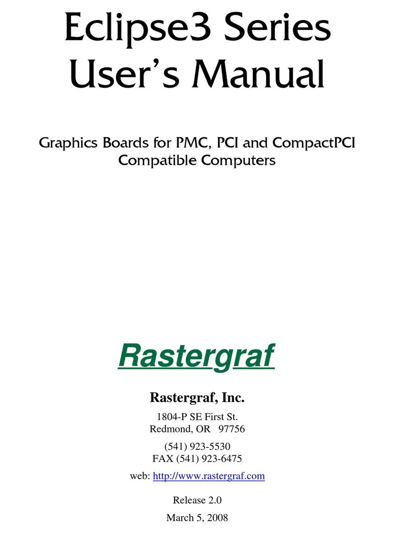
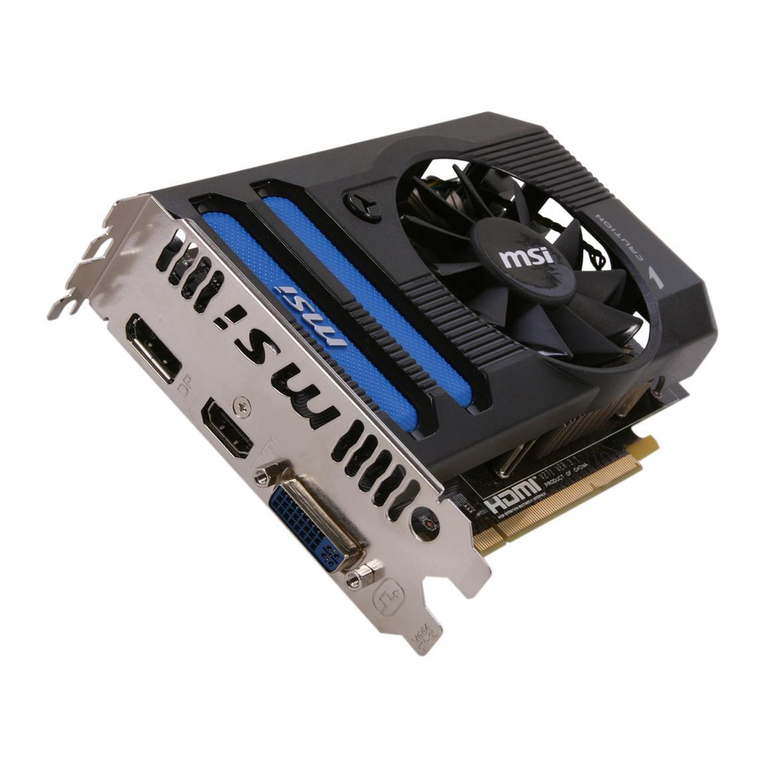
Rastergraf Topaz User manual

Topaz, Stratus, Tropos,
Garnet, and Duros
PMC Graphics Boards
User’s Manual
Rastergraf, Inc.
1810-J SE First St.
Redmond, OR 97756
(541) 923-5530
web: http://www.rastergraf.com
Release 3.7
May 7, 2017
Rastergraf

Table of Contents
INTRODUCTION.......................................................................................................... 0-1
GETTING HELP .......................................................................................................................................... 0-2
BOARD REVISIONS .................................................................................................................................... 0-2
NOTICES .................................................................................................................................................... 0-3
CONVENTIONS USED IN THIS MANUAL ..................................................................................................... 0-4
CHAPTER 1 GENERAL INFORMATION .............................................................. 1-1
1.1 INTRODUCTION ................................................................................................................................... 1-2
1.2 SM731 GRAPHICS CONTROLLER ........................................................................................................ 1-9
1.2.1 Overview ................................................................................................................................. 1-9
1.2.2 Detailed Description.............................................................................................................. 1-10
1.2.3 SM731 Features..................................................................................................................... 1-11
1.3 VIDEO CAPTURE AND PLAYBACK ..................................................................................................... 1-13
1.4 BT835 NTSC/PAL/SECAM DIGITIZER ........................................................................................... 1-16
1.5 AD9882 RGBHV/DVI DIGITIZER .................................................................................................... 1-17
1.6 FLEXIBLE DISPLAY SUPPORT ............................................................................................................ 1-18
1.6.1 TV Display ............................................................................................................................ 1-19
1.6.2 Analog RGB Displays ........................................................................................................... 1-19
1.6.3 STANAG 3350 A-C (Topaz/Duros)...................................................................................... 1-19
1.6.4 Flat Panel Displays ................................................................................................................ 1-20
1.7 FRONT AND REAR PANEL I/O OPTIONS............................................................................................. 1-22
1.8 SOFTWARE SUPPORT......................................................................................................................... 1-25
1.9 ADDITIONAL DETAILS ABOUT SDL.................................................................................................. 1-25
1.10 ADDITIONAL REFERENCES .............................................................................................................. 1-27
CHAPTER 2 SPECIFICATIONS ................................................................................ 2-1
2.1 GENERAL ............................................................................................................................................ 2-2
2.2 SPECIFICATIONS UNIQUE TO TOPAZ, STRATUS, AND GARNET ............................................................ 2-8
2.3 DISPLAY TIMING...............................................................................................................................2-10
2.4 MONITOR REQUIREMENTS ................................................................................................................ 2-12
2.5 VERIFIED DISPLAY AND CAPTURE MODES ....................................................................................... 2-13
2.5.1 Basic Format Evaluations...................................................................................................... 2-13
2.5.2 Maximum Display/Capture Performance .............................................................................. 2-15
2.6 CONFIGURATION INFORMATION ....................................................................................................... 2-17
2.6 SOFTWARE SUPPORT......................................................................................................................... 2-20
CHAPTER 3 CONNECTOR PINOUTS AND CABLE INFORMATION .............. 3-1
3.1 INTRODUCTION ................................................................................................................................... 3-2
3.2 VGA CONNECTOR .............................................................................................................................. 3-5
3.3 DVI-I CONNECTOR ............................................................................................................................. 3-7
3.4 MDR20 CONNECTOR.......................................................................................................................... 3-9
3.4.1 MDR20 Pinout 20A – NTSC/PAL or RGBHV In, NTSC/PAL Out....................................... 3-9
3.4.2 MDR20 Pinout 20B – DVI Input........................................................................................... 3-10
3.5 MDR26 CONNECTOR........................................................................................................................ 3-11
3.5.1 MDR26 Pinout 26A – Video In, Video Out, Ch 1 LVDS Out .............................................. 3-11
3.5.2 MDR26 Pinout 26B – DVI Input, Ch 1 LVDS Out............................................................... 3-12
3.5.3 MDR26 Pinout 26C – Ch 1 and CH 2 LVDS Out................................................................. 3-12
3.6 MDSM CONNECTOR......................................................................................................................... 3-13
3.6.1 Pinout MDSMA – NTSC/PAL or RGBHV In, NTSC/PAL Out........................................... 3-13

3.6.2 Pinout MDSMB – DVI Input ................................................................................................3-14
3.7 S-VIDEO CONNECTOR....................................................................................................................... 3-15
3.8 VGA TO VGA CABLE....................................................................................................................... 3-16
3.9 S-VIDEO ADAPTER CABLES .............................................................................................................. 3-17
3.10 DVI-I MULTIFUNCTION BREAKOUT CABLE.................................................................................... 3-19
3.10.1 C1 – Primary VGA.............................................................................................................. 3-20
3.10.2 C2 – Secondary VGA.......................................................................................................... 3-20
3.10.3 C3 – DVI ............................................................................................................................. 3-21
3.11 DVI-I TO VGA ADAPTERS.............................................................................................................. 3-22
3.12 TOPAZPMC VGA BREAKOUT CABLE............................................................................................. 3-24
3.13 TOPAZPMC VIDEO I/O BREAKOUT CABLE..................................................................................... 3-25
3.14 TOPAZPMC DVI IN ADAPTER CABLE ............................................................................................ 3-26
3.15 TOPAZPMC VIDEO I/O + LVDS BREAKOUT CABLE ...................................................................... 3-27
3.16 TOPAZPMC DVI IN + LVDS BREAKOUT CABLE............................................................................ 3-28
3.17 TOPAZPMC LVDS EXTENSION CABLE .......................................................................................... 3-29
3.18 STRATUSPMC VIDEO I/O BREAKOUT CABLE................................................................................. 3-31
3.19 STRATUSPMC DVI IN ADAPTER CABLE ........................................................................................ 3-32
3.20 CONNECTIONS TO PMC PN1, PN2, AND PN4................................................................................... 3-33
Pn4 Connectors................................................................................................................................ 3-33
3.20.1 Pn1 Connector (all boards).................................................................................................. 3-35
3.20.2 Pn2 Connector (all boards).................................................................................................. 3-36
3.20.3 Pn4 – Dual LVDS Only....................................................................................................... 3-37
3.20.4 Pn4 – Dual LVDS and DVI (In or Out)............................................................................... 3-38
3.20.5 Pn4 - Dual LVDS, DVI (In or Out), Analog Video I/O, VGA............................................ 3-39
3.20.6 Pn4 - Dual LVDS, Dual VGA, Analog Video I/O .............................................................. 3-40
3.20.7 Pn4 - Dual LVDS, VGA, DVI In, DVI Out ........................................................................ 3-41
3.20.8 Pn4 - Dual LVDS, Dual VGA, DVI In................................................................................ 3-42
3.20.9 Pn4 - Dual LVDS, Single VGA........................................................................................... 3-43
3.20.10 Pn4 – RG-101 Compatible VGA Pinout............................................................................ 3-44
CHAPTER 4 INSTALLING YOUR RASTERGRAF GRAPHICS BOARD.......... 4-1
4.1 INTRODUCTION ................................................................................................................................... 4-2
4.2 UNPACKING YOUR BOARD ................................................................................................................. 4-2
4.3 PREPARING FOR INSTALLATION .......................................................................................................... 4-3
4.3.1 Interrupt Settings ..................................................................................................................... 4-3
4.3.2 Address Settings ...................................................................................................................... 4-3
4.3.3 Changing the Jumpers ............................................................................................................. 4-3
4.4 GRAPHICS BOARD INSTALLATION.................................................................................................... 4-10
4.5 INSTALLING IN A PCI BACKPLANE USING A CARRIER ....................................................................... 4-14
4.6 INSTALLING IN A COMPACTPCI BACKPLANE USING A CARRIER ....................................................... 4-17
4.7 FINISHING THE INSTALLATION .......................................................................................................... 4-21
4.7.1 Connecting to the Monitor..................................................................................................... 4-21
4.7.2 Checking your Display.......................................................................................................... 4-22
4.8 USING A RASTERGRAF BOARD IN A PC............................................................................................. 4-23
4.8.1 Single Graphics Board........................................................................................................... 4-23
4.8.2 Multiboard Operation ............................................................................................................ 4-23
4.9 USING A RASTERGRAF BOARD IN A POWERPC ................................................................................. 4-28
4.10 FINAL CHECKS................................................................................................................................ 4-28
CHAPTER 5 PROGRAMMING ON-BOARD DEVICES AND MEMORIES...... 5-1
5.1 INTRODUCTION ................................................................................................................................... 5-2
5.2 SM731 GRAPHICS ACCELERATOR ...................................................................................................... 5-3
5.3 CLOCKS............................................................................................................................................ 5-12
5.3.1 CY22150 Reference Clock.................................................................................................... 5-12
5.4 VIDEO TIMING PARAMETERS ............................................................................................................ 5-13
5.4.1 Application Note: Adjusting the Timing Parameters............................................................. 5-14
5.4.2 Pan and Scroll........................................................................................................................ 5-17
Request for Assistance in Determining Video Timing Parameters ................................................. 5-18
5.5 SYSTEM MANAGEMENT DEVICES AND FUNCTIONS........................................................................... 5-19
5.6 TALK TO ME THROUGH I2C.............................................................................................................. 5-20
5.7 TOPAZ/STRATUS/GARNET AUXILIARY REGISTER ............................................................................. 5-21
5.8 DVI DIGITAL VIDEO OUTPUT ........................................................................................................... 5-22
5.9 ADV7123 AND ADV7120 VGA DACS............................................................................................ 5-24
5.10 AD9882 HIGH SPEED DIGITIZER (STRATUS/GARNET).................................................................... 5-25
5.11 BT835 NTSC/PAL/SECAM VIDEO DECODER ............................................................................... 5-26
5.12 FLASH EEPROM ............................................................................................................................ 5-30
5.13 SERIAL EEPROM........................................................................................................................... 5-31
5.14 INTERRUPTS .................................................................................................................................... 5-31
CHAPTER 6 TROUBLESHOOTING........................................................................ 6-1
6.1 GENERAL PROCEDURES ...................................................................................................................... 6-2
6.2 DEALING WITH THE PCI BUS .............................................................................................................. 6-3
6.3 MAINTENANCE, WARRANTY, AND SERVICE ....................................................................................... 6-3

Tables
Table 1-1 Board Feature Summary................................................................................. 1-3
Table 1-2 SDL Functional Summary............................................................................ 1-26
Table 2-1 Rastergraf Ruggedization Levels Chart.......................................................... 2-7
Table 2-2 BIOS Display Timing Specifications ........................................................... 2-10
Table 2-3 VGA/Windows Platform Display Timing Specifications ........................... 2-10
Table 2-4 SDL Platform Display Timing Specifications............................................. 2-11
Table 2-5 Basic Display/Capture Format Capabilities ................................................ 2-14
Table 2-6 Maximum Display/Capture Format Capabilities.........................................2-16
Table 2-7 Standard Front Panel Board Configurations and Connector Utilization..... 2-18
Table 2-8 Standard Rear Panel Board Configurations and I/O Assignments.............. 2-19
Table 2-9 Front Panel Board Model Compatibility ..................................................... 2-19
Table 2-10 Software...................................................................................................... 2-20
Table 3-1 Front Panel Signal Definitions ....................................................................... 3-3
Table 3-2 Front and Rear Panel Connector Usage.......................................................... 3-4
Table 3-3 Analog (VGA) Video Connector Pinout ........................................................ 3-6
Table 3-4 Tropos DVI-I Connector (Pinout D1) ............................................................ 3-7
Table 3-5 TopazPMC/2 and StratusPMC DVI-I Connector (Pinout D2)....................... 3-8
Table 3-6 Video I/O (VI/O) Front Panel Connector (Pinouts 20A & 20B).................... 3-9
Table 3-7 Video I/O (VI/O) Front Panel Connector (Pinouts 26A-26C) ..................... 3-11
Table 3-8 Video I/O (VI/O) Front Panel Connector (Pinouts MDSMA & MDSMB) . 3-13
Table 3-9 VGA to VGA Cable (A31-00599-1012) ...................................................... 3-16
Table 3-10 TopazPMC S-Video to BNC adapter cable (A31-00709-1003)................. 3-17
Table 3-11 StratusPMC BNC to S-Video Adapter Cable (VAD44) ............................ 3-18
Table 3-12 C1 - Primary VGA Connector.................................................................... 3-20
Table 3-13 C2 - Secondary VGA Connector................................................................ 3-20
Table 3-14 C3 - DVI-D Connector ............................................................................... 3-21
Table 3-15 DVI-I to VGA Adapter............................................................................... 3-22
Table 3-16 TopazPMC VGA Breakout Connector....................................................... 3-24
Table 3-17 TopazPMC Video I/O Breakout Cable....................................................... 3-25
Table 3-18 TopazPMC DVI In Adapter Cable ............................................................. 3-26
Table 3-19 TopazPMC Video I/O + LVDS Breakout Cable........................................ 3-27
Table 3-20 TopazPMC DVI In + LVDS Breakout Cable ............................................3-28
Table 3-21 TopazPMC LVDS Extension Cable (A31-00735-4012)............................ 3-30
Table 3-22 StratusPMC Video I/O Breakout Cable (A31-00735-0036) ...................... 3-31
Table 3-23 StratusPMC DVI In Adapter Cable............................................................ 3-32
Table 3-24 Rear Panel Signal Definitions .................................................................... 3-34
Table 4-1 x86 Supported Video Modes........................................................................4-24
Table 5-1 Standard Graphics Display Formats............................................................. 5-13

Table 5-2 Video Timing Parameter Request Form......................................................5-18
Table 5-3 I2C Device Addresses...................................................................................5-20
Figures
Figure 1-1 Topaz Block Diagram ................................................................................... 1-4
Figure 1-2 Stratus Block Diagram .................................................................................. 1-5
Figure 1-3 Tropos Block Diagram.................................................................................. 1-6
Figure 1-4 Garnet Block Diagram .................................................................................. 1-7
Figure 1-5 Duros Block Diagram .................................................................................. 1-8
Figure 1-6 SM731 Application Block Diagram.............................................................. 1-9
Figure 1-7 SM731 Detail Block Diagram..................................................................... 1-12
Figure 1-8 Video Capture and Playback Support ......................................................... 1-13
Figure 1-9 Capture Buffer and Display Memory.......................................................... 1-14
Figure 1-10 Video Processing Data Path......................................................................1-15
Figure 1-11 Bt835 Video Digitizer Block Diagram ..................................................... 1-16
Figure 1-12 AD9882 High Speed Digitizer Block Diagram ........................................ 1-17
Figure 1-13 Display Channels ......................................................................................1-18
Figure 1-14 DVI Flat Panel Output Block Diagram..................................................... 1-20
Figure 1-15 LVDS Flat Panel Output Block Diagram.................................................. 1-21
Figure 1-16 Front and Rear Panel I/O Options for Topaz ............................................ 1-22
Figure 1-17 Front and Rear Panel I/O Options for Stratus ........................................... 1-23
Figure 1-18 Front and Rear Panel Output Options for Tropos ..................................... 1-23
Figure 1-19 Rear Panel I/O Options for Garnet............................................................ 1-24
Figure 1-20 Rear Panel Output Options for Duros ....................................................... 1-24
Figure 3-1 S-Video Connector...................................................................................... 3-15
Figure 3-2 VGA to VGA Extension Cable (A31-00599-1012).................................... 3-16
Figure 3-3 S-Video to BNC Adapter (A31-00709-1003).............................................3-17
Figure 3-4 BNC to S-Video Adapter Cable (VAD44).................................................. 3-18
Figure 3-5 DVI-I Multifunction Breakout Cable (A31-00735-1012)........................... 3-19
Figure 3-6 Molex 88741-8700 DVI-I to VGA Adapter................................................ 3-22
Figure 3-7 DVI to VGA Adapter Cable (A31-00599-5012) ........................................ 3-23
Figure 3-8 TopazPMC VGA Breakput Cable (A31-00735-2012) ............................... 3-24
Figure 3-9 TopazPMC LVDS Extension Cable (A31-00735-4012) ............................ 3-29
Figure 3-10 MDSM to BNC Breakout Cable (A31-00735-0036)................................3-31
Figure 4-1 Jumper Locations for the Fab Rev 0 TopazPMC Board...............................4-5
Figure 4-2 Jumper Locations for the Fab Rev 1 TopazPMC Board...............................4-5
Figure 4-2 Jumper Locations for the Fab Rev 1 TopazPMC Board...............................4-6
Figure 4-3 Jumper Locations for the Fab Rev 2 TopazPMC Board...............................4-7

Figure 4-4 Jumper Locations for the Fab Rev 1 StratusPMC and TroposPMC Boards. 4-7
Figure 4-4 Jumper Locations for the Fab Rev 1 StratusPMC and TroposPMC Boards. 4-8
Figure 4-5 Jumper Locations for the Fab Rev 1 Garnet and Duros Boards ...................4-9
Figure 4-6 Installation of a PMC Module into an Emerson MVME2604 .................... 4-12
Figure 4-7 Installation of the PMC Module into an Emerson CPV3060...................... 4-13
Figure 4-8 Installation of a PMC Module onto a PCI-PMC Carrier............................. 4-15
Figure 4-9 Installation of a PCI Module into an Emerson MTX.................................. 4-16
Figure 4-10 Installation of a PMC Module onto a 3U CPCI- PMC Carrier................. 4-18
Figure 4-11 Installation of a PMC Module into a 6U CPCI- PMC Carrier.................. 4-19
Figure 4-12 Installing a CompactPCI Board ................................................................ 4-20
Figure 5-1 CY22150 Block Diagram............................................................................ 5-12
Figure 5-2 Video Display Timing Fields...................................................................... 5-15
Figure 5-3 THC63DV164 Block Diagram ................................................................... 5-22
Figure 5-4 THC63DV164 RGB to 24-bit TMDS Mapping Diagram........................... 5-23
Figure 5-5 Bt835 Detailed Block Diagram................................................................... 5-27


Rastergraf
Introduction - 1
Introduction
This manual provides information about how to configure, install, and
program the Rastergraf Silicon Motion SM731-based Topaz, Stratus,
Tropos, Garnet, and Duros PMC graphics display controllers. When used
with appropriate PMC-to-host adapters, PCI and CompactPCI compatible
computers can also be supported.
This manual is broken down into six chapters:
Chapter 1: General Information
Chapter 2: Specifications
Chapter 3: Connector Pinouts and Cable Information
Chapter 4: Installing Your Graphics Board
Chapter 5: Programming Devices and Memories
Chapter 6: Troubleshooting
Chapters 1-3 provide background material about the graphics boards.
Understanding the information in the chapters, however, is not essential
for the hardware or software installation. If you want to perform the
installation as quickly as possible, start with Chapter 4. If you have
problems installing the hardware, refer to Chapter 6 for help.

Rastergraf
Introduction - 2
Getting Help
This installation manual gives specific steps to take to install your
Rastergraf board. There are, however, variables specific to your computer
configuration and monitor that this manual cannot address. Normally, the
default values given in this manual will work. If you have trouble
installing or configuring your system, first read Chapter 6,
“Troubleshooting”. If this information does not enable you to solve your
problems, do one of the following:
1) call Rastergraf technical support at: (541) 923-5530
If your problem is monitor related, Rastergraf technical support will need
detailed information about your monitor.
Board Revisions
This manual applies to the following board revision levels:
Tropos/Stratus Fab Rev 1
Duros/Garnet Fab Rev 1
Topaz Fab Rev 0, 1, 2
Manual Revisions
Revision 3.1 April 2007 Rastergraf version
Revision 3.2 September 2007 Update RIO info
Revision 3.3 February 12, 2008 Fix part numbers, add
LVDS info, change cable info.
Revision 3.4 December 6, 2013 Changes for Topaz Rev 1.
Remove fax, update address, add
RG-101 pinout
Revision 3.5 January 6, 2014 clean up some text in Ch. 3
Revision 3.6 February 7, 2017 clean up and correct tables in
Section 3.20.
Revision 3.7 May 5, 2017 Changes for Topaz Rev 2.
Moved jumpers, added option for
VGA Ch 2 on Ch 1 on DVI-I

Rastergraf
Introduction - 3
Notices
Information contained in this manual is disclosed in confidence and may
not be duplicated in full or in part by any person without prior approval of
Rastergraf. Its sole purpose is to provide the user with adequately detailed
documentation to effectively install and operate the equipment supplied.
The use of this document for any other purpose is specifically prohibited
The information in this document is subject to change without notice. The
specifications of the graphics boards and other components described in
this manual are subject to change without notice. Although it regrets them,
Rastergraf, Inc. assumes no responsibility for any errors or omissions that
may occur in this manual. Customers are advised to verify all information
contained in this document
The electronic equipment described herein generates, uses, and may
radiate radio frequency energy, which can cause radio interference.
Rastergraf, Inc. assumes no liability for any damages caused by such
interference.
Rastergraf, Inc.’s products are not authorized for any use as critical
components in flight safety or life support equipment without the express
consent of the president of Rastergraf, Inc.
These products have been designed to operate in user-provided PMC-
compatible computers. Connection of incompatible hardware is likely to
cause serious damage. Rastergraf assumes no liability for any damages
caused by such incompatibility.
Rastergraf assumes no responsibility for the use or reliability of software
or hardware that is not supplied by Rastergraf, or which has not been
installed in accordance with this manual.
The TopazPMC, StratusPMC, TroposPMC, GarnetPMC, and DurosPMC
graphics boards are manufactured and sold under license from
Curtiss-Wright Controls Embedded Computing (CWCEC). Contact
Rastergraf, Inc. for additional information.
Rastergraf is a trademark of Rastergraf, Inc.
All other trademarks and copyrights are the property of their respective
owners.
Copyright © 2017 by Rastergraf, Inc.

Rastergraf
Introduction - 4
Conventions Used In This Manual
The following list summarizes the conventions used throughout this
manual.
Code
fragments Code fragments, file, directory or path names and
user/computer dialogs in the manual are presented
in the courier typeface.
Commands or
program names
Commands, or the names of executable programs,
except those in code fragments, are in bold.
System prompts
and commands
Commands in code fragments are preceded by the
system prompt, a percentage sign (%), the standard
prompt in UNIX’s C shell, or the hash mark (#),
the standard UNIX prompt for the Super-User.
Keyboard usage <CR> stands for the key on your keyboard labeled
“RETURN” or “ENTER”
Note Note boxes contain information either specific to
one or more platforms, or interesting, background
information that is not essential to the installation.
Caution Caution boxes warn you about actions that can
cause damage to your computer or its software.
Warning! Warning! boxes warn you about actions that can
cause bodily or emotional harm.

Rastergraf
General Information 1-1
Chapter 1
General Information

Rastergraf
1-2 General Information
1.1 Introduction
The Topaz, Stratus, Tropos, Garnet, and Duros comprise a set of closely
related designs that have been tuned to address a variety of requirements.
Originally starting with the Stratus as the fully configured version and
Tropos as the low parts count version, the line was expanded into the
analogous Garnet and Duros which are rugged, conduction cooled
versions adding 2 thermal layers and, on the Duros, the ability to produce
STANAG 3350 A-C output modes.
The final iteration is the Topaz, a non-conduction cooled design, which is
intended to subsume the Stratus and Tropos. It:
a) includes the new features added in the Garnet and Duros,
b) using an MDR26 connector, adds the optional capability to provide
LVDS on the front panel,
c) replaces the Stratus front panel MDSM Video I/O connector with an
MDR20 for easier cable construction,
d) adds a dual front panel VGA connector option,
e) adds the 3.3V local regulator option that was dropped on Garnet and
Duros.
The following page shows a table of the features of the boards in a
comparative format to ease understanding what each version provides.
Following that are block diagrams of each board, and then some
explanatory sections covering the board functions.

Rastergraf
General Information 1-3
Table 1-1 Board Feature Summary
Topaz Stratus/
Garnet
Tropos/
Duros
Silicon Motion SM731 2D/3D engine with 16MB SDRAM yes yes yes
1600x1200 single VGA yes yes yes
1024x768 dual VGA yes yes no
1280x1024 single/1024x768 dual LVDS yes yes yes
1600x1200 single DVI yes yes option
S-Video/NTSC/PAL/SECAM single output yes yes Duros
Interlaced/non-interlaced, Sync-On-Green yes yes Duros
STANAG 3350 A-C output option yes no Duros
DVI Input mode yes yes no
RGBHV, RGB, and STANAG Input modes yes yes no
S-Video/NTSC/PAL/SECAM Input modes yes yes no
Dual front panel VGA connector option yes no no
Dual VGA via DVI b/o cable option yes Stratus no
Dual VGA rear panel option yes yes no
LVDS options – front/rear yes rear only rear only
MDR26 LVDS front panel connector option yes n/a n/a
Single DVI options – front/rear yes yes yes
Composite/S-Video output yes yes yes
MDSM-16 Video I/O connector no Stratus no
MDR20 Video I/O connector yes no no
2 Kb serial EEPROM and LM75 thermal sensor yes yes yes
3.3V & 5V PCI Bus Signaling yes yes yes
33/66 MHz PCI Bus Speed yes yes yes
CCPMC form factor compatible yes yes yes
Full CCPMC version with thermal layers no Garnet Duros
Local 3.3V regulator yes Stratus Tropos
Side 1 only component loading yes yes yes
Field reprogrammable VGA BIOS yes yes yes
SDL Graphics Subroutine Package yes yes yes
SDL-based WindML and BIT yes yes yes
Windows 2K/XP graphics drivers yes yes yes
Windows 2K/XP video input drivers yes yes no
Xfree86 Version 4.3 for Linux and VxWorks yes yes yes
X video in extensions for Linux and VxWorks yes yes no
RG-101 Rear I/O compatible version (PCB Rev 1) yes no no

Rastergraf
1-4 General Information
Figure 1-1 Topaz Block Diagram
MDR-26
Connector
Single
Channel
LVDS
Video
Input/
Output/
RGBHV
or
DVI In
Front
Panel
Version
4
VGA
Connector
VGA Ch 1
Out
PMC (PCI) Bus
On-Chip
Display
Memory
Video
Output
Processor
2D/3D
Drawing
Engines
PCI Bus
Interface
DMA
Engine
Video
Input
Processor
235 MHz
RAMDAC
NTSC/PAL
Video
Encoder
Flat Panel
Drivers
Dual
Channel
LVDS
Encoder
BIOS
Memory
Interface
I
2
C
Controller
PLD Controller
I/O Resource Manager
PLD for STANAG or
YUV/RGB Multiplexer
Analog Devices
AD9882 High Speed
RGB/DVI Digitizer
Conexant Bt835
Video Input
Processor
THine THC63DV164
DVI Output Encoder
BIOS EEPROM
LVDS Out
Video Out
Video In
DVI In
RGB In
Ch 1
Ch 2
Select
VGA Ch 1 Out
DVI Out
32 bit
33/66 MHz
Silicon
Motion
SM731
Graphics
Accelerator
Analog Devices
ADV7120 DAC (STANAG)
VGA Ch 2 Out
Analog Devices
ADV7123 DAC
Video
Input/
Output/
RGBHV
or
DVI In
Rear
Panel
Front
Panel
Version
1
Graphics
VGA Ch 1
Out
MDR-26
Connector
Dual
Channel
LVDS
Front
Panel
Version
2
VGA
Connector
VGA Ch 1
Out
VGA
Connector
VGA Ch 2
Out
Front
Panel
Version
3
VGA
Connector
VGA Ch 1
Out
Graphics
DVI
DVI-I
Connector
VGA Ch 1
Out
VGA Ch 2
Out
DVI Out
Graphics
VGA Ch 2
Out
MDR-20
Connector
Video
Input/
Output/
RGBHV
or
DVI In
Graphics
Dual
Channel
LVDS
Local
3.3V
Regulator
Option
Important Note
Topaz can support
STANAG Out
OR
RGB/DVI/NTSC/PAL
Video Input
but not at the same time

Rastergraf
General Information 1-5
Figure 1-2 Stratus Block Diagram
PMC (PCI) Bus
On-Chip
Display
Memory
Video
Output
Processor
2D/3D
Drawing
Engines
PCI Bus
Interface
DMA
Engine
Video
Input
Processor
235 MHz
RAMDAC
NTSC/PAL
Video
Encoder
Flat Panel
Drivers
Dual
Channel
LVDS
Encoder
BIOS
Memory
Interface
I
2
C
Controller
PLD Controller
I/O Resource Manager
PLD for YUV/RGB
Multiplexer
Analog Devices
AD9882 High Speed
RGB/DVI Digitizer
Conexant Bt835
Video Input
Processor
THine THC63DV164
DVI Output Encoder
BIOS EEPROM
LVDS Out
Video Out
Video In
DVI In
RGB In
Ch 1
Ch 2
Select
VGA Ch 1 Out
DVI Out
32 bit
33/66 MHz
Silicon
Motion
SM731
Graphics
Accelerator
VGA Ch 2 Out
Analog Devices
ADV7123 DAC
Video
Input/
Output/
RGBHV
or
DVI In
Rear
Panel
Option
Front
Panel
Option
Graphics
VGA Ch 1
Out
Graphics
DVI
DVI-I
Connector
VGA Ch 1
Out
VGA Ch 2
Out
DVI Out
Graphics
VGA Ch 2
Out
MDSM
Connector
Video
Input/
Output/
RGBHV
or
DVI In
Graphics
Dual
Channel
LVDS
Local
3.3V
Regulator
Option

Rastergraf
1-6 General Information
Figure 1-3 Tropos Block Diagram
Front
Panel
Option
DVI-I
Connector
VGA Ch 1
Out
VGA Ch 2
Out
DVI Out
PMC (PCI) Bus
On-Chip
Display
Memory
Video
Output
Processor
2D/3D
Drawing
Engines
PCI Bus
Interface
DMA
Engine
Video
Input
Processor
235 MHz
RAMDAC
NTSC/PAL
Video
Encoder
Flat Panel
Drivers
Dual
Channel
LVDS
Encoder
BIOS
Memory
Interface
I
2
C
Controller
PLD Controller
I/O Resource Manager
THine THC63DV164
DVI Output Encoder
BIOS EEPROM
LVDS Out
Video Out
Ch 1
Ch 2
VGA Ch 1 Out
DVI Out
32 bit
33/66 MHz
Silicon
Motion
SM731
Graphics
Accelerator
VGA Ch 2 Out
Analog Devices
ADV7123 DAC
Rear
Panel
Option
Graphics
VGA Ch 1
Out
Graphics
DVI
Graphics
VGA Ch 2
Out
Graphics
Dual
Channel
LVDS
Local
3.3V
Regulator
Option

Rastergraf
General Information 1-7
Figure 1-4 Garnet Block Diagram
PMC (PCI) Bus
On-Chip
Display
Memory
Video
Output
Processor
2D/3D
Drawing
Engines
PCI Bus
Interface
DMA
Engine
Video
Input
Processor
235 MHz
RAMDAC
NTSC/PAL
Video
Encoder
Flat Panel
Drivers
Dual
Channel
LVDS
Encoder
BIOS
Memory
Interface
I
2
C
Controller
PLD Controller
I/O Resource Manager
PLD for
YUV/RGB Multiplexer
Analog Devices
AD9882 High Speed
RGB/DVI Digitizer
Conexant Bt835
Video Input
Processor
THine THC63DV164
DVI Output Encoder
BIOS EEPROM
LVDS Out
Video Out
Video In
DVI In
RGB In
Ch 1
Ch 2
Select
VGA Ch 1 Out
DVI Out
32 bit
33/66 MHz
Silicon
Motion
SM731
Graphics
Accelerator
VGA Ch 2 Out
Analog Devices
ADV7120 DAC
Video
Input/
Output/
RGBHV
or
DVI In
Rear
Panel
Graphics
VGA Ch 1
Out
Graphics
DVI
Graphics
VGA Ch 2
Out
Graphics
Dual
Channel
LVDS

Rastergraf
1-8 General Information
Figure 1-5 Duros Block Diagram
Video Out
VGA Ch 1 Out
DVI Out
VGA Ch 2 Out
PMC (PCI) Bus
On-Chip
Display
Memory
Video
Output
Processor
2D/3D
Drawing
Engines
PCI Bus
Interface
DMA
Engine
Video
Input
Processor
235 MHz
RAMDAC
NTSC/PAL
Video
Encoder
Flat Panel
Drivers
Dual
Channel
LVDS
Encoder
BIOS
Memory
Interface
I
2
C
Controller
PLD Controller
I/O Resource Manager
PLD for STANAG
THine THC63DV164
DVI Output Encoder
BIOS EEPROM
LVDS Out
Ch 1
Ch 2
32 bit
33/66 MHz
Silicon
Motion
SM731
Graphics
Accelerator
Analog Devices
ADV7120 DAC
STANAG >> VGA Ch 1
or
Second VGA >> VGA Ch 2
Rear
Panel
Graphics
VGA Ch 1
Out
Graphics
DVI
Graphics
VGA Ch 2
Out
Graphics
Dual
Channel
LVDS
Figure 1-5 Duros Block Diagram
This manual suits for next models
4
Table of contents
Other Rastergraf Video Card manuals
Popular Video Card manuals by other brands

Gainward
Gainward 8400GS 512MB DVI HDMI brochure

EVGA
EVGA GeForce GTX 680 SC Signature 2 specification

Compaq
Compaq 3Dlabs OXYGEN VX1 installation guide

Texas Instruments
Texas Instruments TVP4020 PERMEDIA 2 Reference manual

TNT2-VANTA
TNT2-VANTA Pavilion 4500 - Desktop PC datasheet

Legend
Legend QDI I740 AGP manual