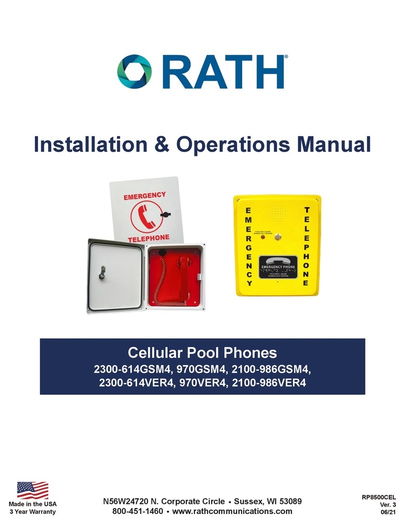
Rath 2100-958NSR Installation instructions manual

Area of Refuge/Two-Way Communication
System Mounting Guide
N56W24720 N. Corporate Circle Sussex, WI 53089
800-451-1460 www.RATHCommunications.com 09/20
Made in the USA
3 Year Warranty

Thank you for purchasing a RATH® Emergency Communication System. We are the largest Emergency
Communication Manufacturer in North America and have been in business for over 35 years.
We take great pride in our products, service, and support. Our Emergency Products are of the highest quality.
Our experienced customer support teams are available to remotely assist with site preparation, installation,
and maintenance. It is our sincere hope that your experience with us has and will continue to surpass your
expectations.
Thank you for your business,
®
N56W24720 N. Corporate Circle Sussex, WI 53089
800-451-1460 www.RATHCommunications.com
Table of Contents
Call Box Mounting . . . . . . . . . . . . . . . . . . . . . . . . . . . .
Base Station Mounting . . . . . . . . . . . . . . . . . . . . . . . .
Distribution Module Mounting . . . . . . . . . . . . . . . . . .
Supervisor Mounting . . . . . . . . . . . . . . . . . . . . . . . . . .
Signage Mounting . . . . . . . . . . . . . . . . . . . . . . . . . . . .
System Mounting Locations . . . . . . . . . . . . . . . . . . . .
Page 3-8
Page 9-14
Page 15-16
Page 16
Page 17
Page 18
Call Box Mounting
Call Boxes should be mounted so that the push button is 48” from the oor.
Flush Mount Call Boxes:
2100-958NSR, 2400-808NSP, 2100-958NMBR, 2400-808NMP, SUBPNBX (back box only)
Page 3
A AA
1.00” [25.40]
1.00” [25.40]
ø0.19” [ø4.85]
5.25” [133.35]
7.50” [190.50]
9.50” [241.30]
6.00” [152.40]
3.00” [76.20]
5.50” [139.70]
2.25” [57.15]
8.00” [203.20]
1.50” [38.10]
5.50” [139.70]
1.20” [30.48]
0.59” [14.91]
0.89” [22.65]
R0.44” [R11.11]
1/8” HEX
INTERIOR ELEVATION
A BACK BOX TOP
BACK BOX FRONT
COVER FRONT
BACK BOX BOTTOM
BACK BOX SIDE

2100-958SSRC2, 2400-808SSPC2, RP7700042PC (back box only)
Page 4

2100-958SR, SUBPNBX (back box only)
Page 5
A AA
SWITCH
LED
123
456
789
0 #
*
Enter
Record
Play/Pause
Stop
www.rathmicrotech.com
Rath Microtech 800-451-1460
RJ11C
PHONE JACK
24V AC/DC
J3
BATTERY
BACKUP 24V
AC/DC
SPADE PHONE
CONNECTION
ø0.19” [ø4.85]
9.75” [247.65]
12.50” [317.50]
6.00” [152.40]
3.00” [76.20]
5.50” [139.70]
2.25” [57.15]
8.00” [203.20]
1.50” [38.10]
5.50” [139.70]
1.20” [30.48]
0.59” [14.91]
0.89” [22.65]
R0.44” [R11.11]
1/8” HEX
INTERIOR ELEVATION
ABACK BOX TOP
BACK BOX FRONT
COVER REARCOVER FRONT
BACK BOX BOTTOM
BACK BOX SIDE
0.12” [3.048]

Surface Mount Call Boxes:
2100-956SR, 2400-805SP, 2100-956SRM, 2400-805SPM, 2100-956RR, 2400-805RP
Page 6
BACK BOX END BACK BOX SIDE
BACK BOX FRONTCOVER FRONT
7.25” [184.15]4.82” [122.30]
1.86” [47.24]
ø0.88” [ø22.23]
0.77” [19.60]
0.93” [23.72]
4.75” [120.70]
7.25” [184.14]
0.37” [9.27]
0.39” [9.78]
0.24” [6.10]
0.19” [4.83]
1.54” [39.14]
1.54” [39.14]
0.48” [12.19] 0.48” [12.19]
1.67” [42.37]
2.38” [60.33]
2.75” [69.85]
2.25” [57.15]
2.38” [60.33]
1.67” [42.37]
0.48” [12.15]

Page 6
2100-984LR, 2400-805LP, 2100-984LRC1, 2400-805LPC1
Page 7
SWITCH
LED
SPEAKER
RJ11C TELEPHONE LINE
1 2 3
4 5 6
7 8 9
0 #
*
Enter
Record
Play/Pause
Stop
www.rathmicrotech.com
Rath Microtech 800-451-1460
RJ11C
PHONE JACK
J3
BATTERY
BACKUP
24V AC/DC
COVER OUTSIDE COVER INSIDE
BASE INSIDE
5.23” [132.93]
6.63” [168.28]
9.88” [250.83]
3.19” [80.96]
BOTTOM
SIDE
6.38” [161.93]
5.63” [161.93]
7.62” [193.63] 9.60” [243.77]

2100-956SSRC2, 2400-805SSPC2
Page 8
SWITCH
1 2 3
4 5 6
7 8 9
0 #
*
LED
Enter
Record
Play/Pause
Stop
www.rathmicrotech.com
Rath Microtech 800-451-1460
RJ11C
PHONE JACK
24V AC/DC
J3
BATTERY
BACKUP 24V
AC/DC
SPADE PHONE
CONNECTION
4.25” [107.95]
3.00” [76.2]
CLEAR PROTECTIVE COVER
BACK BOX BOTTOM
BACK BOX RIGHT SIDEBACK BOX LEFT SIDEBACK BOX FRONT
BACKCOVER FRONT
6.67” [169.42]
10.045” [255.14]
1.94” [49.21]
3.13” [79.38]
3.25” [82.55]
2.50” [63.50]
3.00” [76.20]
3.75” [95.25]
1.63” [41.28]
1.50” [38.10]
2.50” [63.50]
ø0.50” [ø12.70]
ø0.50” [ø12.70]

Base Station Mounting
RATH® recommends mounting the Base Station 60” from the oor to the center of the unit.
2500-205D, 2500-210D
Page 9
Y
G
R
B
Y
G
R
B
Y
G
R
B
Y
G
R
B
Y
G
R
B
Y
G
R
B
Y
G
R
B
Y
G
R
B
Y
G
R
B
Y
G
R
B
12345678910
HOOK SWITCH
Y
G
R
B
Y
G
R
B
FRONT PANEL/COVER
LEFT SIDE
BOTTOM SIDE
CONTROL INSIDE
11.60” [294.64]
12.56” [319.09]
0.82” [20.72]
0.69” [17.46]
0.22” [5.71]
1.98” [50.19]
0.69” [17.46]
4.02” [102.07]
0.25” [6.35]
0.13” [3.18]
0.32” [8.05]
1.03” [26.25]
1.27” [32.38]
11.60” [294.64]
12.56” [319.09]
0.33” [8.49] 5.81” [147.48]
ø0.28” [ø7.18]
11.60” [294.64]
0.84” [21.27]
4.34” [110.17]
1.68” [42.67]
ø0.50” [ø12.70]
ø0.88” [ø22.23]
0.45” [11.41]
0.69” [17.50]

2500-205PSS, 2500-210PSS
Page 10
Y
G
R
B
Y
G
R
B
Y
G
R
B
Y
G
R
B
Y
G
R
B
Y
G
R
B
Y
G
R
B
Y
G
R
B
Y
G
R
B
Y
G
R
B
12 3 4 5 6 7 8 9 10
HOOK SWITCH
Y
G
R
B
Y
G
R
B
FRONT PANEL/COVER
LEFT SIDE
BOTTOM SIDE
CONTROL INSIDE
ø0.88” [ø22.23]
0.69” [17.50]
ø0.28” [ø7.18]
0.84” [21.27]
11.60” [294.69]
1.68” [42.67]
5.81” [147.48]
0.33” [8.49]
12.56” [319.09]
11.61” [294.96]
0.32” [8.05]
1.27” [32.38]
1.03” [26.25]
1.98” [50.19]
0.22” [5.71]
0.82” [20.72]
0.69” [17.46]
0.69” [17.46]
0.13” [3.18]
4.02” [102.07]
0.25” [6.35]
13.81” [350.84]
13.81” [350.84]

2500-205B, 2500-210B, 2500-12RC, 2500-16RC
Page 11
FRONT VIEW BACK PANEL
BOTTOM VIEW
ø0.20” [ø5.08]
6.00” [152.40]
8.75” [222.25]
6.00” [152.40]
6.00” [152.40]
12.00” [304.8]
15.07” [382.78]
1.00”
[25.47]
12” [304.80]
6.50” [165.16]
R0.25”
[R6.35]
R0.10” [R2.54] 8.75” [222.25]
1.50” [38.10]
1.38” [34.93]

2500-205FM, 2500-210FM, 2500-12RCF, 2500-16RCF
Page 12
FRONT VIEW
SIDE VIEW
CABINET BACK BOX
INSIDE VIEW WITH FRONT PANEL OPENED
ø0.25” [ø6.35]
ø0.25” [ø6.35] ø0.88” [ø22.23]
12.00” [304.69]
3.00” [76.2]
1.00” [25.42]
1.50” [38.09] 1.50” [38.09]
1.00” [25.40]2.00” [50.80]
14.00” [355.57]
16.11” [409.08]
15.62” [396.75]
1.81” [46.04]
6.00” [152.40]
6.00” [152.40]
1.50”
[37.97]

Page 12
2500-28RC, 2500-36RC, 2500-56XRC, 2500-76XRC, 2500-76XRC, 2500-116XRC
Page 13
BACK PANEL
TOP
FRONT SIDE
CABINET
TOP
SIDE
FRONT
17.06 [433.34]
5.19
[131.70]
Ø0.220
21.03
[534.29]
20.30 [515.62]
Ø0.220
Ø0.500
17.06
[433.34]
6.65 [168.92]
1.50 [38.10]
1.58 [40.01]
SIDE
6.88 [174.76] 6.88 [174.76]
6.30
[160.03]
6.30
[160.03]
7.93 [201.30]
1.50 [38.10]
1.38 [34.93]
0.86 [21.84]

2500-28RCF, 2500-36RCF 2500-56XRCF, 2500-76XRCF, 2500-96XRCF, 2500-116XRCF
Page 14
SIDE
Ø0.25 [Ø6.35]
0.24 [5.97]
FRONT
TOP
25.00 [635.06]
21.13
[536.75] 20.66 [524.81]
6.00
[152.41]
6.00
[152.41]
4.33
[109.99]
1.50 [38.10]
0.24 [5.97]
KNOCKOUTS (TOP AND BOTTOM OF CABINET) KNOCKOUTS (TOP AND BOTTOM OF CABINET)
Ø0.88 [Ø22.23] Ø0.25
[Ø6.35] Ø0.88 [Ø22.23]
0.99 [25.15]
22.99 [584.05] 3.50
[88.91]
10.00 [254.02]
3.00
[76.21]
3.06
[77.73]
1.01 [25.65]
1.50 [38.10]
2.99
[76.00]
3.50
[88.91]

Page 15
Distribution Module Mounting (Command System Only)
1-36 Zone (PE) Distribution Module
Option 1: Wall Mounting
• Use diagram as a guide for pre-drilling holes in wall
• Remove top panel and drill out keyholes for mounting
• Secure to wall with provided screws
Option 2: Shelf Mounting (shelf not provided by RATH®)
• Place on shelf mounted in 19” server rack
11.81”
7.87”
1-116 Zone (GE)
Option 1: Wall Mounting
• Use diagram below to pre-drill holes into wall
• Secure screws in wall
• Attach Distribution Module to wall using the keyholes on backside
17.19”
16.28”
1.57”

Option 2: Rack Mounting (rack not provided by RATH®)
• Attach included brackets to sides of Distribution Module
• Secure to 19” server rack using compatible machine
screws for your rack
Page 16
Option 3: Shelf Mounting (shelf not provided by RATH®)
• Place on open rack mounted shelf
Supervisor Board Mounting (2500-__SPRVSR)
Mount the 2500 Supervisor Board to a wall using the provided swing arm bracket or to a 19” rack (not included).

Instruction Sign
• Mount above or adjacent to each Call Box
Tactile/Braille Sign
• Mount between 48”-60” from oor to lowest tactile characters
Illuminated Sign
• 120/277vac powered
• Mount above 60” but below 80” from the oor to top of the sign
• Single gang back box recommended
Photo Luminescent
• Mount above 60” but below 80” from the oor to top of the sign
Directional Signs
• Mount 48” from the oor to the bottom of the sign
• Located in hallway adjacent to Area of Refuge
Signage Mounting
7049 7049SS
7087 7044
7050
7041
7047
7050E
7041E
7047E
Page 17

System Mounting Locations
In Elevator Landings:
In Stairwells:
Page 18
This manual suits for next models
42
Table of contents
Other Rath Caller ID Box manuals