Rato RV140 Series User manual

439534 Rev. 4 08.17.11 BY Printed in U.S.A.
CAUTION:
Read and follow all Safety Rules and Instructions
before attempting to operate this engine.
Owner’s Manual
(American)
Vertical Shaft, 4-Stroke, OHV,
140cc Gasoline-Powered Engine
RV140
SERIES ENGINE

2
WARNING: In order to prevent ac-
cidental starting when setting up, trans-
porting, adjusting or making repairs,
always disconnect spark plug wire and
place wire where it cannot come in contact
with spark plug.
WARNING: Engine exhaust, some of its
constituents, and certain vehicle compo-
nents contain or emit chemicals known to
the State of California to cause cancer and
birth defects or other reproductive harm.
CAUTION: Muffler and
other engine parts become
extremely hot during oper-
ation and remain hot after
engine has stopped. To
avoid severe burns on contact,
stay away from these areas.
SAFETY RULES
Your safety and the safety of others is
important. We have provided important
safety information in this manual and on
the engine itself. A safety message alerts
you to potential hazards and risks which
could hurt you or others. Each message is
preceeded by a safety alert symbol and
one of the three following words:
DANGER: indicates a hazard which,
if not avoided, will result in death or
serious injury, could damage your engine
and/or void your warranty.
WARNING: indicates a hazard which,
if not avoided, could result in death or
serious injury.
CAUTION: indicates a hazard which,
if not avoided, could result in minor to
moderate injury.
I. GENERAL OPERATION
• Read, understand, and follow all instruc-
tions on the engine and in this manual
before starting. Be thoroughly familiar
with the controls and the proper use of
the machine before starting.
• Do not change the engine governor set-
ting or overspeed the engine.
• Do not run the engine at a low load at a
low speed for a long period of time.
• Use only specified grades of gasoline
and oil.
• Keep area around fuel filler cap clean.
• Maintain the air filter and change the oil
as indicated in the Maintenance section
of this manual.
• Make repairs when needed. Do not
operate engine with anything damaged
or missing.
II. SAFE HANDLING OF GASOLINE
Use extreme care in handling gasoline.
Gasoline is extremely flammable and the
vapors are explosive.
• Extinguish all cigarettes, cigars, pipes
and other sources of ignition.
• Use only an approved container.
• Never remove gas cap or add fuel with
the engine running. Allow engine to cool
before refueling.
• Never refuel the machine indoors.
• Never store the machine or fuel contain-
er where there is an open flame, spark
or pilot light such as a water heater or on
other appliances.
• Never fill containers inside a vehicle, on
a truck or trailer bed with a plastic liner.
Always place containers on the ground
away from your vehicle before filling.
• Remove gas-powered equipment from
the truck or trailer and refuel it on the
ground. If this is not possible, then
refuel such equipment with a portable
container, rather than from a gasoline
dispenser nozzle.
• Keep the nozzle in contact with the rim
of the fuel tank or container opening at
all times until fueling is complete. Do
not use a nozzle lock-open device.
• If fuel is spilled on clothing, change
clothing immediately.
• Never overfill fuel tank. Replace gas
cap and tighten securely.
III. GENERAL SERVICE
• Never run engine inside a closed area.
• Never make adjustments or repairs
with the engine running. Disconnect the
spark plug wire and keep the wire away
from the spark plug to prevent accidental
starting.
• Periodically check nuts and bolts for
proper tightness.
• Never tamper with safety devices.
Check their proper operation regularly.
• Keep engine free of grass, leaves, or
other debris build-up. Clean oil or fuel
spillage. Allow machine to cool before
storing.
• Maintain or replace safety and instruc-
tion labels, as necessary. 15
SERVICE NOTES

14
EMISSION RELATED PARTS INCLUDE THE FOLLOWING:
1) Fuel Metering System:
a) Gasoline carburetor assembly and its internal components.
b) Fuel filter (if so equipped)
c) Carburetor gaskets
d) Fuel pump (if so equipped)
2) Air Induction System including:
a) Intake pipe/manifold
b) Air cleaner
3) Ignition System including:
a) Spark plug
b) Ignition module/coil
4) Catalytic Muffler Assembly (if so equipped) including:
a) Muffler gasket
b) Exhaust manifold
5) Miscellaneous including:
a) Hoses, belts and connectors.
3
Safety Rules .............................................2
Product Specifi cations..............................4
Pre-Operation...........................................4
Operation..................................................5
Maintenance Schedule.............................6
Maintenance..........................................6-7
Service and Adjustments..........................7
Troubleshooting .....................................8-9
Torque Values ..........................................9
Repair Parts.......................................10-11
TABLE OF CONTENTS
IMPORTANT: This engine is shipped WITHOUT OIL OR GASOLINE.
KNOW YOUR ENGINE
READ THIS OWNER'S MANUAL AND ALL SAFETY RULES BEFORE OPERATING
YOUR ENGINE. Compare the illustrations with your engine to familiarize yourself with
the location of various controls and adjustments. Save this manual for future reference.
Fuel tank
Warning label
Carburetor
Muffler
Spark plug
Oil cap with dipstick
Air
filter
Gasoline filler cap
Primer (optional)
Start/Stop
switch
(optional)
Recoil
starter
handle
E.P.A. label
Fuel filter

4
Serial Number:
Date of Purchase:
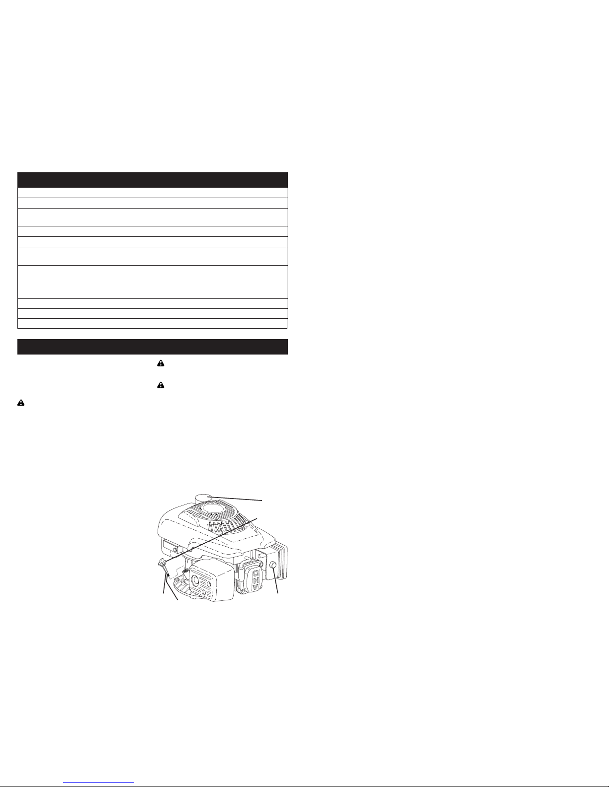
•The model and serial numbers will be found on the rear of the engine housing.
Record both serial number and date of purchase in the space provided above.
Gasoline Capacity / Type: 1.14 Quarts / 1 Litre (Unleaded Regular)
Oil Capacity: 15.5 Ounces / 0,45 Litres
Oil Type (API SG–SL):SAE 10W-30 (or SAE 30 above 10°C/40°F,
or SAE 5W-30 below 0°C/32°F)
Spark Plug: N.G.K. BP6ES or BPR6ES
(Gap: .030" / 0,76 mm) Champion N11YC or RN11YC
N.H.S.P. F6TC or F6RTC
Torch F6TC or F6RTC
Dry Weight: 24.91 lbs. / 11.3 kg Displacement: 140cc / 139,36ml
Bore x Stroke: 65 x 42mm Carburetor Idle Speed: 1900 RPM (±100)
Valve Clearance (cold engine):Intake: 0.15mm (±0.02); Exhaust: 0.20mm (±0.02)
PRODUCT SPECIFICATIONS
PRE-OPERATION
BEFORE STARTING ENGINE
ADD OIL
Your lawnmower is shipped without oil in
the engine. For type /grade oil to use, see
the Maintenance section of this manual.
CAUTION: DO NOT overfill engine with
oil, or it will smoke on startup.
1. Be sure lawnmower is level.
2. Remove oil fill cap from oil fill spout.
3. Engine holds 15.5 oz. of oil. Pour oil
slowly. Do not overfill. Wait one minute
to allow oil to settle. Use gauge on oil
fill cap/dipstick for checking level. Insert
dipstick into the tube and rest the oil fill
cap on the tube. DO NOT thread the
cap into the tube when taking reading.
4. Insert and tighten oil fill cap/dipstick.
IMPORTANT:
• Check oil level before each use. Add oil
if needed. Fill to full line on dipstick.
• Change the oil after every 25 hours of
operation or each season. You may
need to change the oil more often
under dusty, dirty conditions. See “TO
CHANGE ENGINE OIL” in the Mainte-
nance section of this manual.
ADD GASOLINE
• Fill fuel tank to bottom of tank filler neck.
Do not overfill. Use fresh, clean, regular
unleaded gasoline with a minimum of 87
octane. Do not mix oil with gasoline. Pur-
chase fuel in quantities that can be used
within 30 days to assure freshness.
CAUTION: Wipe off any spilled oil or
fuel. Do not store, spill or use gasoline
near an open flame.
CAUTION: Alcohol blended fuels
(called gasohol or using ethanol or metha-
nol) can attract moisture which leads to
separation and formation of acids during
storage. Acidic gas can damage the fuel
system of an engine while in storage. To
avoid engine problems, the fuel system
should be emptied before storage of 30
days or longer. Empty the gas tank, start
the engine and let it run until the fuel lines
and carburetor are empty. Use fresh fuel
next season. See Storage Instructions for
additional information. Never use engine
or carburetor cleaner products in the fuel
tank or permanent damage may occur.
Oil fill cap /
dipstick
Gasoline
filler cap
Lower mark
Upper
mark
Primer
(optional)
13
II. EMISSION CONTROL SYSTEM WARRANTY
Emission Control System Warranty (ECS Warranty) for 1997 and later model engines:
(a) Applicability: This warranty shall apply to 1997 and later model year engines. The ECS War-
ranty Period shall begin on the date the new engine or equipment is purchased by/delivered to
its original, end-use purchaser/owner and shall continue for 24 consecutive months thereafter.
(b) General Emissions Warranty Coverage: HUSQVARNA OUTDOOR PRODUCTS INC. war-
rants to the original, end-use purchaser/owner of the new engine or equipment and to each
subsequent purchaser/owner that each of its engines is...
(1) Designed, built and equipped so as to conform with all applicable regulations adopted by
the EPA and CARB pursuant to their respective authority, and
(2) Free from defects in materials and workmanship which, at any time during the ECS War-
ranty Period, may cause a warranted emissions-related part to fail to be identical in all material
respects to the part as described in the engine manufacturer’s application for certification.
The ECS Warranty only pertains to emissions-related parts on your engine, as follows:
(1) Any warranted, emissions-related parts that are not scheduled for replacement as required
maintenance in the Owner’s Manual shall be warranted for the ECS Warranty Period. If any
such part fails during the ECS Warranty Period, it shall be repaired or replaced by HUSQVAR-
NA OUTDOOR PRODUCTS INC. according to Subsection (4) below. Any such part repaired
or replaced under the ECS Warranty shall be warranted for the remainder of the ECS Warranty
Period.
(2) Any warranted, emissions-related part that is scheduled only for regular inspection as speci-
fied in the Owner’s Manual shall be warranted for the ECS Warranty Period. A statement in
such written instructions to the effect of “repair or replace as necessary” shall not reduce the
ECS Warranty Period. Any such part repaired or replaced under the ECS Warranty shall be
warranted for the remainder of the ECS Warranty Period.
(3) Any warranted, emissions-related part that is scheduled for replacement as required main-
tenance in the Owner’s Manual shall be warranted for the period of time prior to the first sched-
uled replacement point for that part. If the part fails prior to the first scheduled replacement, the
part shall be repaired or replaced by HUSQVARNA OUTDOOR PRODUCTS INC. according
to Subsection (4) below. Any such emissions-related part repaired or replaced under the ECS
Warranty shall be warranted for the remainder of the ECS Warranty Period prior to the first
scheduled replacement point for such emissions-related part.
(4) Repair or replacement of any warranted, emissions-related part under this ECS Warranty
shall be performed at no charge to the owner at a HUSQVARNA OUTDOOR PRODUCTS INC.
Authorized Warranty Service Facility.
(5) When the engine is inspected by a HUSQVARNA OUTDOOR PRODUCTS INC. Authorized
Warranty Service Facility, the owner shall not be held responsible for diagnostic costs if the
repair is deemed warrantable.
(6) HUSQVARNA OUTDOOR PRODUCTS INC. shall be liable for damages to other original
engine components or approved modifications proximately caused by a failure under warranty
of any emission-related part covered by the ECS Warranty.
(7) Throughout the ECS Warranty Period, HUSQVARNA OUTDOOR PRODUCTS INC. shall
maintain a supply of warranted emission-related parts sufficient to meet the expected demand
for such emission-related parts.
(8) Any HUSQVARNA OUTDOOR PRODUCTS INC. authorized and approved emission-re-
lated replacement part may be used in the performance of any ECS Warranty maintenance or
repairs and will be provided without charge to the purchaser/owner. Such use shall not reduce
HUSQVARNA OUTDOOR PRODUCTS INC.’s ECS Warranty obligations.
(9) Unapproved, add-on, modified, counterfeit and/or “grey market” parts may not be used
to modify or repair a HUSQVARNA OUTDOOR PRODUCTS INC. engine. Such use voids
this ECS Warranty and shall be sufficient grounds for disallowing an ECS Warranty claim.
HUSQVARNA OUTDOOR PRODUCTS INC. shall not be held liable hereunder for failures of
any warranted parts of a HUSQVARNA OUTDOOR PRODUCTS INC. engine caused by the
use of such an unapproved, add-on, modified, counterfeit and/or “grey market” part.

12
I. CALIFORNIA AND FEDERAL EMISSION CONTROL WARRANTY STATEMENT
YOUR WARRANTY RIGHTS AND OBLIGATIONS
The California Air Resources Board (CARB) and the United States Environmental Protection
Agency (EPA), together with HUSQVARNA OUTDOOR PRODUCTS INC. are pleased to ex-
plain the Emission Control System Warranty on your new small off-road engine. New small
off-road engines must be designed, built and equipped to meet stringent anti-smog standards
for the state of California and the federal government. HUSQVARNA OUTDOOR PRODUCTS,
INC. will warrant the emission control system on your engine for the periods of time listed below
provided there has been no abuse, neglect, unapproved modification or improper maintenance
of your engine.
Your emission control system may include parts such as the carburetor, ignition, intake and ex-
haust systems. HUSQVARNA OUTDOOR PRODUCTS, INC. will repair your engine at no cost
to you for diagnosis, replacement parts and labor, should a warrantable condition occur.
MANUFACTURER’S EMISSION CONTROL SYSTEM WARRANTY COVERAGE:
Emission control systems on 1997 and later model year engines are warranted for two years as
hereinafter noted. If, during such warranty period, any emission-related component or system on
yourengineisfound to be defective inmaterialsor workmanship, repairs orreplacementwillbe per-
formed by a HUSQVARNA OUTDOOR PRODUCTS, INC. Authorized Warranty Service Facility.
PURCHASER’S/OWNER’S WARRANTY RESPONSIBILITIES:
As the small off-road engine purchaser/owner, you are responsible for the completion of all re-
quired maintenance as listed in your factory supplied Owner’s Manual. For warranty purposes,
HUSQVARNA OUTDOOR PRODUCTS, INC. recommends that you retain all receipts covering
maintenance on your engine. However, HUSQVARNA OUTDOOR PRODUCTS, INC. cannot
deny warranty solely because of the lack of receipts or for your failure to ensure the completion
of all scheduled maintenance.
As the small off-road engine purchaser/owner, you should, however, be aware that HUSQVAR-
NA OUTDOOR PRODUCTS INC. may deny any and/or all warranty coverage or responsibility
if your engine, or a part/component thereof, has failed due to abuse, neglect, improper main-
tenance or unapproved modifications, or the use of counterfeit and/or “grey market” parts not
made, supplied or approved by HUSQVARNA OUTDOOR PRODUCTS, INC.
You are responsible for presenting your engine to a HUSQVARNA OUTDOOR PRODUCTS
INC. Authorized Warranty Service Facility as soon as a problem occurs. The warranty repairs
should be completed in a reasonable amount of time, not to exceed 30 days.
Warranty service can be arranged by contacting either your selling dealer or a HUSQVARNA
OUTDOOR PRODUCTS INC. Authorized Warranty Service Facility. To locate the HUSQVAR-
NA OUTDOOR PRODUCTS INC. Authorized Warranty Service Facility nearest you at
1(800)487-5951 or go to www.husqvarna.com and click on Support.
IMPORTANT NOTE: This warranty statement explains your rights and obligations under the
Emission Control System Warranty (ECS Warranty), which is provided to you by HUSQVARNA
OUTDOOR PRODUCTS INC. pursuant to California and federal law. See also the “Limited
Warranties for HUSQVARNA OUTDOOR PRODUCTS, INC.,” which is enclosed herewith on
a separate sheet, also provided to you by HUSQVARNA OUTDOOR PRODUCTS, INC. The
ECS Warranty applies only to the emission control system of your new engine. If there is any
conflict in terms between the ECS Warranty and the HUSQVARNA OUTDOOR PRODUCTS,
INC. Warranty, the ECS Warranty shall apply except in circumstances where the HUSQVARNA
OUTDOOR PRODUCTS, INC. Warranty may provide a longer warranty period. Both the ECS
Warranty and the HUSQVARNA OUTDOOR PRODUCTS, INC. Warranty describe important
rights and obligations with respect to your new engine.
Warranty service can be performed only by a HUSQVARNA OUTDOOR PRODUCTS, INC.
Authorized Warranty Service Facility. When requesting warranty service, evidence must be
presented showing the date of the sale to the original purchaser/owner. The purchaser/owner
shall be responsible for any expenses or other charges incurred for service calls and/or trans-
portation of the product to/from the inspection or repair facilities. The purchaser/owner shall
also be responsible for any and/or all damages or losses incurred while the engine is being
transported/shipped for inspection or warranty repairs.
IF YOU HAVE ANY QUESTIONS REGARDING YOUR WARRANTY RIGHTS AND RESPON-
SIBILITIES, YOU SHOULD CONTACT HUSQVARNA OUTDOOR PRODUCTS, INC. at
1(800) 487-5951. 5
OPERATION
TO STOP ENGINE
(all models)
• To stop engine, release operator presence control bar and/or place engine START/
STOP switch (if equipped) in the OFF position.
TO START ENGINE
(all models)
NOTE: Due to protective coatings on the engine, a small amount of smoke may be pres-
ent during the initial use of the product and should be considered normal.
1. Place engine START/STOP switch (if equipped) in the ON position.
CHOKE
FAST
MODELS WITH THROTTLE:
2. Move handle mounted throttle control
lever in FAST position.
SLOW
FAST
MODELS WITH CHOKE:
2. To start a cold engine, move handle
mounted choke control lever to
CHOKE position.
MODELS WITH PRIMER:
2. To start a cold engine, push primer
three (3) times before trying to start.
Use a firm push. This step is not
usually necessary when starting an
engine which has already run for a few
minutes.
NOTE: In cooler weather it may be neces-
sary to repeat priming steps. In warmer
weather over priming may cause flooding
and engine will not start. If you do flood
engine, wait a few minutes before attempt-
ing to start and do not repeat priming
steps.
ALL MODELS
(continued)
3. Hold operator presence control bar
down to the handle and pull starter
handle quickly. Do not allow starter
rope to snap back.
MODELS WITH CHOKE:
4. Slowly move choke control lever to
FAST position after engine starts.

6
LUBRICATION
Use only high quality detergent oil rated
with API service classification SJ–SL.
Select the oil's SAE viscosity grade
according to your expected operating
temperature.
10W-30
30
5W-30
Change the oil after every 25 hours of
operation or at least once a year if the
lawn mower is not used for 25 hours in
one year.
Check the crankcase oil level before
starting the engine and after each five (5)
hours of continuous use. Tighten oil plug
securely each time you check the oil level.
TO CHANGE ENGINE OIL
NOTE: Before tipping engine to drain oil,
empty fuel tank by running engine until
fuel tank is empty.
1. Disconnect spark plug wire from spark
plug and place wire where it cannot
come in contact with plug.
2. Remove oil fill cap/dipstick; lay aside
on a clean surface.
3. Tip engine on its side as shown and
drain oil into a suitable container. Rock
engine back and forth to remove any
oil trapped inside of engine.
Container
Oil fill cap /
dipstick
Lower
mark
Upper
mark
MAINTENANCE
4. Wipe off any spilled oil from side of
engine.
5. Fill engine with oil. Slowly pour oil
down the oil fill spout into the engine.
6. Wait one minute to allow oil to settle.
Use guage on oil fill cap/dipstick for
checking level. Insert dipstick into
the tube and rest the oil fill cap on the
tube. DO NOT thread the cap into the
tube when taking reading.
Check for Loose Fasteners
Check Engine Oil level
Change Engine Oil
Clean Air Filter
Replace Air Filter Paper Cartridge
Inspect Muffler
Replace Fuel Filter
Replace Spark Plug
Clean Cylinder Head of Debris
Empty fuel system or add Stabilizer
Replace Fuel Tank
BEFORE
EACH
USE
FIRST
20
HOURS
EVERY
50 HOURS
OR SEASON
EVERY
100
HOURS
EVERY
THREE
YEARS
BEFORE
STORAGE
1- Change more often if operating under a heavy load or in high outdoor temperatures.
2- Service more often if operating in dirty or dusty conditions.
11
KEY PART
NO. NO. QTY. DESCRIPTION
1 532 43 75-56 1 Cover, Cylinder Head
2 532 43 75-57 1 Gasket, Cylinder Head
3 532 43 75-58 1 Spark Plug
4 532 43 75-59 1 Oil Dipstick Assembly
5 532 43 75-62 1 Recoil Starter Assembly
6 532 43 75-63 1 Handle, Recoil Stater
7 532 43 75-64 1 Service Kit, Carburetor (Includes Insulator Plate,
Insulator Plate Gasket and Caburetor Gasket)
8 532 43 75-65 1 Carburtor Assembly
9 532 43 75-66 1 Gasket, Air Cleaner
10 532 43 75-67 1 Breather Tube
11 532 43 75-68 2 Nut, Air Cleaner
12 532 43 75-69 1 Case, Air Clearner
13 532 43 75-70 1 Air Cleaner Assembly
14 532 43 75-71 1 Cover, Air Cleaner Case
15 532 43 93-77 1 Air Filter
16 532 43 75-72 1 Cover, Muffler
17 532 43 75-73 1 Muffler Assembly (Includes hardware)
18 532 43 75-74 1 Gasket, Exhaust Port
19 532 43 75-75 1 Fuel Cap Assembly
20 532 43 75-76 1 Fuel Tank Assembly (Includes hardware)
21 532 43 75-77 1 Service Kit, Fuel Tank
(Includes Fuel Hose and Hose Clamps)
22 532 43 75-80 1 Ignition Coil
23 532 43 93-78 1 Cap, Spark Plug
24 532 43 75-81 1 Brake Assembly
25 532 43 75-82 1 Primer Bulb Assembly (Includes Hose and Clips)
26 532 43 75-83 1 Shroud Assembly (Includes hardware)
27 532 43 93-79 1 Spring, Governor
28 532 43 93-80 1 Throttle (Governor) Control Lever Set
29 532 43 93-81 1 Throttle Control Bracket Assembly
30 532 43 93-82 1 Brackets, Fuel Tank (RH and LH)
31 532 43 93-84 1 Blower Housing
32 532 43 93-85 1 Flywheel Assembly (Nuts, Washer and Key)
NOT ILLUSTRATED:
- - 532 43 75-84 1 Engine Assembly (Shroud not included)
REPAIR PARTS

10
REPAIR PARTS
7
Tab
Cartridge
Filter cover
Slot
7. Continue adding small amounts of
oil and rechecking the dipstick until it
reads full. DO NOT overfill, or engine
will smoke on startup.
8. Always be sure to retighten oil fill cap/
dipstick before starting engine.
9. Reconnect spark plug wire to spark
plug.
IN-LINE FUEL FILTER
The fuel filter should be replaced every
100 hours or twice each season. If fuel fil-
ter becomes clogged, obstructing fuel flow
to carburetor, replacement is required.
1. With engine cool, remove filter and
plug fuel line.
2. Place new fuel filter in position in fuel
line as shown.
3. Be sure there are no fuel line leaks and
clamps are properly positioned.
4. Immediately wipe up any spilled gaso-
line.
ENGINE
Warranty repairs must be performed by an
authorized engine manufacturer's service
outlet. Tampering with, removing or alter-
ing of any part of the intake, fuel or ex-
haust system, or emission control system
may increase emissions beyond the legal
limit and void your warranty.
ENGINE SPEED
Your engine speed has been factory set.
Any attempt to increase engine speed may
result in personal injury. If you believe that
the engine is running too fast or too slow, you
can adjust the governor tab as follows:
1. Disconnect spark plug wire from spark
plug and place wire where it cannot
come in contact with plug.
2. Start engine as described in the Op-
eration section of this manual.
3. Move choke cable from “OPEN” to
“RUNNING” position.
SERVICE AND ADJUSTMENTS
Governor tab
AIR FILTER
Your engine will not run properly and may
be damaged by using a dirty air filter.
Replace the air filter every 100 hours of
operation or every season, whichever oc-
curs first. Service air cleaner more often
under dusty conditions.
TO CLEAN AIR FILTER
1. Remove cover.
2. Carefully remove cartridge.
3. Clean by gently tapping on a flat sur-
face. If very dirty, replace cartridge.
CAUTION: Petroleum solvents, such as
kerosene, are not to be used to clean car-
tridge. They may cause deterioration of the
cartridge. Do not oil cartridge. Do not use
pressurized air to clean or dry cartridge.
4. Install cartridge, then replace cover.
3. Bend governor tab up for higher engine
speed; down a for lower engine speed.
IMPORTANT: If you have any questions,
lack the tools or professional ability, take
your engine to a qualified service center
for repair and adjustment.
MAINTENANCE
Fuel
Filter
Clamp

8
Does not start 1. Dirty air filter. 1. Clean or replace air filter as
shown in the “Maintenance”
section of this manual.
2. Out of fuel. 2. Fill fuel tank as shown in the
“Maintenance” section
of this manual.
3. Stale fuel. 3. Empty fuel tank and refill tank
with fresh, clean gasoline.
4. Dirt or water in fuel. 4. Empty fuel tank and refill tank
with fresh, clean gasoline.
5. Spark plug wire is 5. Connect wire to spark plug.
disconnected.
6. Dirty or bad spark plug. 6. Clean or replace spark plug.
7. Bad spark plug wire. 7. Replace spark plug wire.
8. Piston ring is worn, 8. Clean or replace piston ring.
broken or sticking.
9. Leaking cylinder gasket. 9. Replace cylinder gasket.
10. Valves out of adjustment. 10. Adjust valve clearance
(see Product Specifications).
11. Vent in filler cap clogged. 11. Clean filler cap vent.
12. Carburetor float is 12. Clean or replace the
sticking or damaged. carburetor float.
13. Carburetor jet is 13. Clean or replace the
clogged or damaged. carburetor jet.
14. Control bar in released 14. Depress control bar to
position. handle.
15. Control bar defective. 15. Replace control bar.
Loss of power 1. Dirty air filter. 1. Clean or replace air filter as
shown in the “Maintenance”
section of this manual.
2. Dirt or water in fuel. 2. Empty fuel tank and refill tank
with fresh, clean gasoline.
3. Piston ring is worn, 3. Clean or replace piston ring.
broken or sticking.
4. Leaking cylinder gasket. 4. Replace cylinder gasket.
5. Valves out of adjustment. 5. Adjust valve clearance
(see Product Specifications).
6. Carburetor jet is 6. Clean or replace the
clogged or damaged. carburetor jet.
7. Muffler clogged or damaged. 7. Clean or replace muffler.
8. Oil level too high. 8. Check oil level as shown in
the “Maintenance” section
of this manual.
9. Excessive carbon buildup 9. Clean combustion chamber.
in combustion chamber.
TROUBLESHOOTING - See appropriate section in manual unless directed
to an authorized Service Center.
TROUBLESHOOTING
PROBLEM CAUSE CORRECTION
9
Engine stops 1. Dirty air filter. 1. Clean or replace air filter as
or does not shown in the “Maintenance”
idle smoothly section of this manual.
2. Dirt or water in fuel. 2. Empty fuel tank and refill tank
with fresh, clean gasoline.
3. Dirty or bad spark plug. 3. Clean or replace spark plug.
4. Excessive carbon buildup 4. Clean combustion chamber.
in combustion chamber.
5. Tie rod head is worn. 5. Replace tie rod.
Engine is 1. Cooling fins clogged. 1. Clean cooling fins.
overheating 2. Oil level too low. 2. Add oil as shown in the
“Maintenance” section
of this manual.
3. Engine speed too high. 3. Adjust governor screw
as shown in the
“Service & Adjustments”
section of this manual.
4. Muffler clogged or damaged. 4. Clean or replace muffler.
Excessive 1. Bent crankshaft, 1. Contact a qualified service
vibration disconnected flywheel center.
or noise or broken piston ring.
Starter rope 1. Engine flywheel brake is on 1. Depress control bar to
hard to pull when control bar is released. upper handle before
pulling starter rope.
2. Bent crankshaft. 2. Contact a qualified service
center.
Engine is 1. Oil level too high. 2. Check oil dipstick. If oil level
emitting bluish is over upper mark, drain oil
black smoke until at recommended level.
TORQUE VALUES
Connecting Rod Bolt M10 12 N/m (1,2 kg/m)
Cylinder Head Bolt M12 22 N/m (2,2 kg/m)
Flywheel Nut M14 x 1.5 73 N/m (7.4 kg/m)
Crankcase Cover Bolt M8 x 1.5 26 N/m (2,6 kg/m)
Valve Clearance Adjusting Nut M6 x 0.5 10 N/m (1.0 kg/m)
Valve Rocker Arm Bolt M8 x 1.25 24 N/m (2.4 kg/m)
ITEM SPECIFICATION TORQUE VALUE
TROUBLESHOOTING
PROBLEM CAUSE CORRECTION
TROUBLESHOOTING - See appropriate section in manual unless directed
to an authorized Service Center.
Table of contents
Other Rato Engine manuals
Popular Engine manuals by other brands

Briggs & Stratton
Briggs & Stratton 90000 series Operator's manual

Sumitomo
Sumitomo Beier Variator Series Maintenance manual

Altronic
Altronic 791950-8 installation instructions

Westerbeke
Westerbeke 58 Technical manual

Volvo Penta
Volvo Penta IPS Operator's manual

Volvo Penta
Volvo Penta 3.0GL-B Operator's manual