Rato R3000IS User manual

3.0KW INVERTER GENERATOR
MAINTENANCE MANUAL

This maintenance manual contents regulations which should comply to in daily
maintenance and trouble removal on generator.
Please make sure serviceman could read this manual anytime.
This maintenance manual describes the correct maintaining methods. Any
personal injury or death or equipment damage, which because ignorance on these
regulations, our company would remove the responsibility.
NOTICE
All rights reserved by our company. Any reprinting without the written
permission of our company is expressly prohibited.

SAFETY NOTICE
Your human safety and property are very important as well as others .Please ready following
safety notice in this manual and on generator decals, each safety notice has a symbol .
Failure to follow this instruction could result in extreme severe injury.
Failure to follow this instruction might result in severe injury.
Failure to follow this instruction might result in injury.
Failure to follow this instruction, your generator or other property would be
damaged.
If no torque written, please refer to appendix -- Torque Table.

CONTENTS
°GENERAL INFORMATION ........................................................................................... 6
1-1Main Components ......................................................................................................... 6
1-2General parameter ......................................................................................................... 7
MAINTENANCE ............................................................................................................. 9
2-1Maintenance table ......................................................................................................... 9
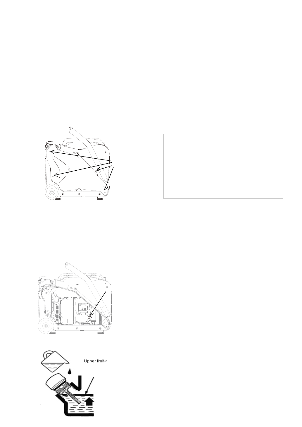
2-2Engine oil .................................................................................................................... 10
2-3Air cleaner .................................................................................................................. 11
2-4Clean fuel strainer ....................................................................................................... 12
2-5Spark arrestor .............................................................................................................. 12
2-6Spark plug ................................................................................................................... 13
2-7 Valve clearance adjustment ..................................................................................... 13
FAILURE PREDICTION AND REPAIR ....................................................................... 16
3-1Failure prediction ........................................................................................................ 16
3-1-1Start difficultly .................................................................................................. 16
3-1-2Power insufficient ............................................................................................. 18
3-1-3Speed unstable .................................................................................................. 19
3-1-4Can't ignite ....................................................................................................... 19
3-1-5Oil overheating ................................................................................................. 20
3-1-6Abnormal sound ............................................................................................... 20
3-1-7No DC output ................................................................................................... 21
3-1-8Generator Stator Winding too hot .................................................................... 21
3-1-9Indicator light judgment ................................................................................... 22
3-2Repair preparation ...................................................................................................... 23
3-2-1Safety factors .................................................................................................... 23
3-2-2Special tools ..................................................................................................... 24
3-3Disassemble diagram .................................................................................................. 25

3-4Gasoline engine .......................................................................................................... 26
3-4-1Starter recoil/fly wheel/ignition coil ................................................................. 26
3-4-2Carburetor ........................................................................................................ 31
3-4-3Stepping motor ................................................................................................. 33
3-4-4Cylinder head ................................................................................................... 34
3-4-5Crankshaft/piston ............................................................................................. 41
3-5Generator .................................................................................................................... 47
3-5-1Fuel tank ........................................................................................................... 47
3-5-2Muffler .............................................................................................................. 48
3-5-3Frame seat assy/Frame/Frequency converter .................................................. 50
3-5-4Control panel .................................................................................................... 53
3-5-5Appearance diagram ........................................................................................ 56
dWIRE CONNECTING DIAGRAM ............................................................................... 57
4-1Wire connecting schematic diagram ........................................................................... 57

GENERAL INFORMATION
1-1 Main Components
Left cover
Wheel
Hand bar
Control panel
Cylinder head cover
Air cleaner
Fuel tank cap
Cushion
Shroud
Oil dipstick
Hand bar
Recoil starter

1-2 General parameter
Generator model
R3000IS/R3000ISP
Motor
Type
Silent inverter generator
Frequency /Hz
50Hz/60Hz
Rated voltage /V
100V/120V/220V/230V/240V
Max power /kVA
3.1
Rated power /kVA
2.8
Power Factor
1
Waveform deviation factor/%
≤%3
Noise (3/4 load)
65dB
DC output / V-A
12V/8A
Engine
Engine model
R210-I
Engine type
OHV
Displacement /cc
212
Fuel type
Gasoline
Engine
Fuel tank capacity /L
7L
Rated load continuum running
time /h
5
Engine oil capacity /mL
0.55
Spark plug model
F6RTCOr NGK model:BPR6ESS
Starting system
Recoil starter
Diameter
L*W*H /mm
605×432×493
Net weight /kg
37kg

1-3 Repair standard
Components
Items
Standard
Limitation
Gasoline
engine
Max unload speed
Cylinder pressure
3600±100
0.45~0.69/600rpm
--
--
Cylinder
Inner diameter
70~70.015
70.065
Piston
Piston skirt outer diameter
Piston-cylinder clearance
Inner diameter of piston pin hole
Piston pin outer diameter
Clearance between Piston pin and piston pin
hole
69.975~69.985
0.015~0.04
18.002~18.008
17.992~17.998
0.004~0.016
69.925
0.13
18.018
17.982
0.036
Piston ring
set
Piston ring sets side-gapVfirst ring/second
ring
Piston ring sets close gap:
first ring/second ring
0.03~0.07
--
--
0.55~0.8075
0.6~0.8575
0.14
--
--
1.1075
1.1575
Connecting
rod
Inner diameter of smaller end
Inner diameter of bigger end
Oil clearance of bigger end
Big-end side gap:
18.011~18.022
30.22~30.23
0.035~0.055
0.75~1.35
18.06
30.27
0.12
1.55
Crankshaft
Crank outer diameter
30.175~30.185
30.145
Valve
Valve clearance Intake / Exhaust
Outer diameter of valve stem
Inner diameter of intake valve guide
Outer diameter of exhaust valve guide
Exhaust / Intake
Contact width of valve seat
Spring free length
0.05~0.10
0.05~0.10
5.5~5.512
5.5~5.512
0.7~0.9
30.5
--
--
5.560
5.560
2.0
29.5
2
Camshaft
Height of cam Intake
Exhaust
Journal outer diameter
27.59
27.56
14.166~14.184
27.29
27.26
--
Crankcase
cover
Inner diameter of camshaft hole
14.2~14.218
12.248
Spark plug
Clearance
0.7-0.8
--
Cap of spark
plug
Resistance
10kΩ
--

MAINTENANCE
2-1 Maintenance table
Regular maintenance contributes to safety, economic, no malfunction and environmental
protection.
Exhaust contents toxic carbon monoxide, please stop the engine before
maintenance. If you have to implement the maintenance when generator
running, please make sure the working area is draughty.
Regular maintenance tableV
Regular maintenance table
Each time
20h or the first
month of begin to
use (3).
50h or every
3 months (3)
100h or
every 6
months (3)
300h or
every year
(3)
Engine oil
Check oil
level
○
Replace
○
○
Air cleaner
Check
○
Clear
○(1)
Fuel cup
Clear
○
Spark plug
Clear
○
Replace
Valve clearance
Re-adjust
○(2)
Cylinder head
cover
Clear
Every 300h (2)
Fuel tank and
strainer
Clear
Every two years (2)
Fuel hose
Replace
Every two years (2)
(1) Please increase the maintenance frequency if generator used in dusty area.
(2) These items should be maintained by franchised dealer.
(3) These items should be maintained in proper time interval as requested to insure
generator’s life.

2-2 Engine oil
1) Put generator on horizontal plane.
2) Loosen the bolts as marked, remove the
cover. (Pull the cover back slightly and
then pull it up).
3) Loosen the oil dipstick, and empty the oil
in crankcase
4) Put generator on horizontal plane, adding
new oil until to the upper limit. Tighten the
oil dipstick.
5) Assemble the cover, tighten bolts
Note Every time before use generator,
place it on horizontal plane, stop the engine
and check oil level.
1.Take the oil dipstick and clean the oil.
2.Put dipstick in crankcase but tighten it, and
check the oil level.
3.If the oil level is low, please add
recommended oil until the upper level.
If skin contacts to engine oil too
frequently, this might result in skin
cancer. Please clean the oil on your skin
clearly with soap and water immediately.
For environmental protection, please
dispose the oil properly. We recommended
that put oil in a sealed container and send it
to relevant recycle bin. Do not throw oil
into refuse dump or other place.
Recommended engine oil:
SAE 15W -40
Recommended engine oil standard:
API Standard: SE or higher
Oil capacity: 0.38L
Bolts
Oil dipstick

2-3 Air cleaner
Dirty air cleaner will affects the air into carburetor. For reducing carburetor faulty, please
maintain the air cleaner regularly (As maintenance table shows) and increase the maintenance
frequency if generator used in dusty area.
Use gasoline or inflammable solvent to clean air cleaner element could
result in fire or explosion. Please clean the element with soap water of
uninflammable solvent.
Start the generator without air cleaner assembly is prohibited, which will
increase engine abrasion.
1) Loosen bolts as marked, remove cover, take the screwR,remove air cleaner coverS.
2) Check air cleaner element, make sure it is complete and clean.
3) If the element is dirty, please clean foam element with detergent, squeeze the water and
then drop a drop of oil, squeeze the element.
4) Assemble the element and air cleaner cover.
Bolts
Cover of
air cleaner
Bolt of air
cleaner

2-4 Clean fuel strainer
Fuel strainer is designed for preventing dust into
carburetor. If generator isn’t used for a long time,
please clean fuel strainer after empty fuel tank.
1) Remove the cover (refer to air cleaner
maintenance step 1), empty fuel tank.
2) Squeeze clipSTpull it down, and pull the
fuel hoseT out, which connected to fuel
tank.
3) Remove fuel strainer.
4) Clean fuel strainer with gasoline.
5) Dry it and assemble it back.
6) Assemble fuel hose and clip back, open
fuel switch, check if any fuel leakage on
fuel strainer.
7) Assemble cover back.
2-5 Spark arrestor
Gasoline is flammable and explosive. Smoking, open fire and spark are prohibited
in working area.
After reassembling generator, please check if any fuel leakage before start the
generator and make sure work area is dry.
Hyperthermal muffler could result in serious scale. Please maintain muffler after
it cool-down.
In regard to clean spark arrestor, please refer to maintenance table. Remove spark arrestor after
generator cool-down. If spark arrestor is damaged, please replace it. Clean the carbon deposition with
wire brush. Assemble spark arrestor back, tighten it with screw.

2-6 Spark plug
Use incorrect model or caloricity of spark
arrestor could decrease engine performance
and damage it.
If keep engine running, spark plug and muffler
would very hot. Please be careful and don’t
touch them.
1) Remove the cover (refer to air cleaner
maintenance step 1), spark plug sleeve
and cap.
2) Put spark plug kit (provide with
generator) into spark plug, loosen it and
take it down.
3) Check spark plug, the model is F6RTC
(or NGK model: BPR6ES)
If electrode is damaged, insulator is
broken, please replace it. If spark plug
could be used, then clean the carbon
deposition on it with wire brush.
4) Adjusting the gap of spark plug, you can
bend the electrode slightly to keep the
gap between 0.70-0.80 (mm).
5) Check the spark plug retainer. When
assemble spark plug, turn it in screw with
hand to avoid improper assembly.
6) After put spark plug on retainer, press it
tightly with spark plug wrench.
The torque of spark plug: 15 N*m
Spark plug should be assemble
properly and tightly, if not, it may damage
the engine.
Please use recommended or the
same standard spark plug. It is prohibited
to use improper spark plug with improper
caloricity.
0.7-0.8mm
Side
electrode
Wire brush
ei

2-7 Valve clearance adjustment
There always be clearance between valve end and its transmitted parts, in case of contraction
which would effect engine work. If the clearance is in excess, it would result in higher back-
pressure and higher noise (abnormal noise from valve) and decrease engine performance. If
the clearance is insufficient, it would make the valve can’t be sealed totally, which might result
in abnormal performance or burning the working surface of relevant parts of valve.
Generally, after 100h or 1 year using, you have to check the valve clearance and adjust it.
! Disassemble these parts in turn: spark plug cap, spark plug, cylinder head cover and gasket.
! Pull the starter coil to make the piston on the top dead center.
! Measure the clearance of valve.
! If the clearance is beyond the standard, please adjust it.
!
Please measure the clearance after engine cool-down.
LC9:F
,6G:
36F I
6
I6GG:
LC9:F:69J:F
Feeler gauge

! Adjust valve clearance.
Adjustment steps: loosen the tighten bolt, turn the adjustment nut to a proper position, and
tighten the adjustment nut.
Valve clearance
Intake
0.05~0.10mm
Exhaust
0.05~0.10mm
Adjust the bolt
Valve clearance
Tighten
Decrease
Loosen
Increase
Excess valve clearance: Both valves open behind, which will decrease the
time of air intake and exhaust, lower the opening height of valves, make engine has
insufficient air intake and can’t exhaust clearly, and result in power decrease. Besides, it
will increase the hit between relevant parts of valve and increase parts abrasion.
Insufficient valve clearance: In engine working, heat will expand parts which push valves
away, and result in incomplete sealing of valve, power decrease and valve surface burning,
even makes valves hit piston.
56J:
56J:
Screwdriver
Wrench

Part 3 Trouble determine and maintenance
3-1 Trouble determine
3-1-1 Start-up difficult
Phenomenon
Causes
Methods of elimination
Cylinder
compression
normal
Spark
plug
norm
al
Fuel
system
abnorm
al
Poor flow
of oil or
oil does
not flow
No fuel oil in the oil tank
Add fuel oil
The vent hole on the oil tank
is blocked
Evacuate the blocking
The main metering jet is
improperly adjusted or
blocked
Re-adjust or clean, blow open
The needle valve hole is
blocked
Dismantle the needle valve for repairing,
cleaning and blowing
The float is stuck or
damaged
Repair the float
oil blow
fluently
Fuel is dirty or deterioration
replace oil
oil mixed with water
replace oil
Too much fuel in the cylinder
Discharge of oil, and dry the spark plug
electrodes
The fuel marking No. is
wrong
use the correct label
Fuel
suppl
y is
norm
al
High
voltage
wire
spark is
normal
The spark
plug
bad
Electrode dirty,
carbon deposition
Clearing away the dirt and carbon deposit
Insulator damage, electrode
severe ablation
replace spark plug
The electrode gap is wrong
Adjust the electrode gap
High
voltage
wire
without
spark
The spark
plug
normal
High voltage wire is
damaged
Replace high voltage wire
Ignition coil is damaged
Replace the motor stator
Magnet demagnetization
replace the fly wheel
The trigger is damaged
replace trigger
The clearance between the
ignition coil and the flywheel
is abnormal
adjust the gap

phenomenon
Causes
Methods of elimination
Cylinder
compression
is bad
Fuel
supply is
normal
ignition
system is
normal
Piston ring wearing limit
Replace with new piston ring
Piston ring break off
replace
Cementation of the piston
ring
Clear away the carbon deposit
Spark plug gasket not
installed or not tightened
Installed gasket and tighten it
The junction surface of the
cylinder body and cylinder
cover
Check the unevenness of the cylinder
cushion, cylinder body, and cylinder cover
junction surface
Tighten the bolts on the cylinder cover as
per the torque required and in a certain
sequence
Air leakage of the valve
Check the valve clearance and the valve
air-tightness, and repair it when necessary
l If the generator still cannot be started, please send it to our authorized distributor for maintenance and
repair.
Spark plug inspection
warning
l Ensure that there is no overflowing fuel oil outside the generator,
and the sparkplug is not soaked by the fuel oil.
l To prevent fire, do not let the spark get close to the spark plug hole.
l When you test the spark plug, it is forbidden to use wet hands to hold the high-voltage
power lines of the spark plug.
! Turn the fuel switch to "OFF" position, and put away the carburetor petrol.
! Remove the spark plug cap and spark plugs.
! Pull the starter handle and let out of the unburned gas.
! Install the spark plug cap.
! Turn the switch to "ON" position
! Let spark plugs of the negative electrode (the threaded portion) through the cylinder head connected to
ground, pull the starter handle spark and observed state.

3-1-2 Underpower
Phenomenon
Causes
Methods of elimination
The rotating
speed increases
slowly or even
the rotating
speed drops
down or there is
flameout when
the accelerator
is stepped on
Fuel oil
supply
system
There is air in the oil line or the oil line
is blocked
Drain the air, clearing the oil line
Improper adjustment of the main
metering jet
Re-adjust the main metering jet
The needle valve opening and the main
metering jet in the carburetor are
blocked
Cleaning, blowing open
The switch of oil tank is blocked
Clean and replace the bad parts
There is carbon deposit in the
combustion chamber
Clear away the carbon deposit
The air filter is blocked
Clean the filter element r
Improper
compression
The piston, cylinder and the piston ring
are worn.
Replace the wearing parts
There is air leakage in the junction
surface of the cylinder body and the
cylinder cover
Replace the cylinder cushion
The valve clearance is too big (too
small)
Re-adjust it
The valve is not sealed tightly
Repair it
Inspection of the cylinder pressure.
! Drain the oil in the oil tank.
! Loosen the oil draining bolt of the carburetor, and drain the
gasoline.
● Dismantle the spark plug cap and the spark plug, and install the
cylinder pressure gauge on the spark plug hole.
! Pull the starter for several times, and measure the cylinder pressure.

3-1-3 Unstable speed
Phenomenon
Causes
Methods of elimination
Tapping sound
of the generator
The piston, cylinder and piston ring wear too
seriously
Replace the wearing parts
The piston pin and the pin hole wear too
seriously
Replace the piston or the
piston pin
The small end of the connecting rod wears
too seriously
Replace the connecting rod
Detonation
Overheat of the generator
Check the cause and eliminate it
Carbon deposit in the combustion chamber
Clear away the carbon
deposit
The gasoline is unqualified
Replace with qualified gasoline
Failure of
ignition of the
generator
There is water in the float chamber
Clean the float chamber
The electrode clearance of the spark plug is not
correct
Adjust the electrode clearance
Fault of the ignition coil
Check and replace the damaged
parts
3-1-4 Failure of ignition
Phenomenon
Causes
Methods of elimination
Failure of ignition
Fuel supply series
The fuel oil is used up
Adding fuel oil
The carburetor is blocked
Check the oil line and clearing out
it.
here is oil leakage in the float
chamber.
Repair the float needle valve
The needle valve is stuck.
Dismantle the float chamber and
eliminate the fault.
Ignition series
The sparking plug
breakthrough, and there is
short circuit of the carbon
deposit
Replace the spark plug

The side electrode of the spark
plug falls off
Replace the spark plug, and
eliminate the stuff that falls off
The high-voltage cable falls off
replace it
The ignition coil will
breakthrough and cause short
circuit
Replace the motor stator
The stopping line falls on the
machine
Find out the short circuit point and
re-insulate it.
Others
Serious cylinder scuff, the
valve falls off
Repair and replace the damaged
parts
3-1-5 Overheating of the generator
Phenomenon
Causes
Methods of elimination
Overheat of
the
generator
Insufficient engine oil
Add sufficient engine oil
Blocking of the exhaust port
Clearing the exhaust port
Air leakage of fan cover
Repairing the damaged
place
Blocking due to the sundries in the cooling fans
Clearing the cooling fans
The deformation of the connecting rod will cause wearing of
the piston and the cylinder hole.
Replacing the connecting
rod
The cylinder, piston and piston ring are worn
Replacing the wearing parts.
Improper adjustment of the speed controller of the generator,
which will cause that the rotation speed is too high.
Re-adjust the speed
controller
3-1-6 Abnormal sound
Phenomenon
Causes
Methods of elimination
Tapping sound
The piston, cylinder and piston ring are worn.
Replacing the wearing parts.
The connecting rod, the piston pin and the pin hole
are damaged.
Replacing the wearing parts.
The crankshaft main journal wear
Replace the bearing
The piston ring will break off.
Replacing the piston ring
the valve clearance is
too big
Adjust the valve clearance
This manual suits for next models
1
Table of contents
Other Rato Portable Generator manuals