Rato RV550 User manual

RV550
Service Manual
Chongqing RATO Technology Co., Ltd.

This Manual covers specifications that shall be followed in the process of regular maintenance and
service and troubleshooting of general-purpose gasoline engine products.
Make sure the product's maintenance staff can refer to this Manual at any time.
This Manual describes correct methods to service this equipment. The Company does not undertake
any liability for any personal casualty and equipment damage caused due to ignoring these rules.
Note:
The copyright of this Manual belongs to the Company, it is not allowed to reproduce it without written
consent of the Company, and corresponding responsibility will be taken for violation.

0
Safety Warnings
It's very important to keep you and other's safety. Please carefully read the extremely important safety
warnings that we have described in the Service Manual and on the engine. There is the symbol and one
of three kinds of tips (Danger, Warning, Caution) in front of each safety warning. Details are as follows:
Failed to follow instructions, extremely serious injury or death will be caused.
Failed to follow instructions, very serious injury or death may be caused.
Failed to follow instructions, the injury may be caused.
Failed to follow instructions, your gasoline engine and other properties may be damaged.
NOTE

1
Contents
Part I Introduction ..................................................................................................................................2
1-1 Components of general-gasoline engine ....................................................................................... 2
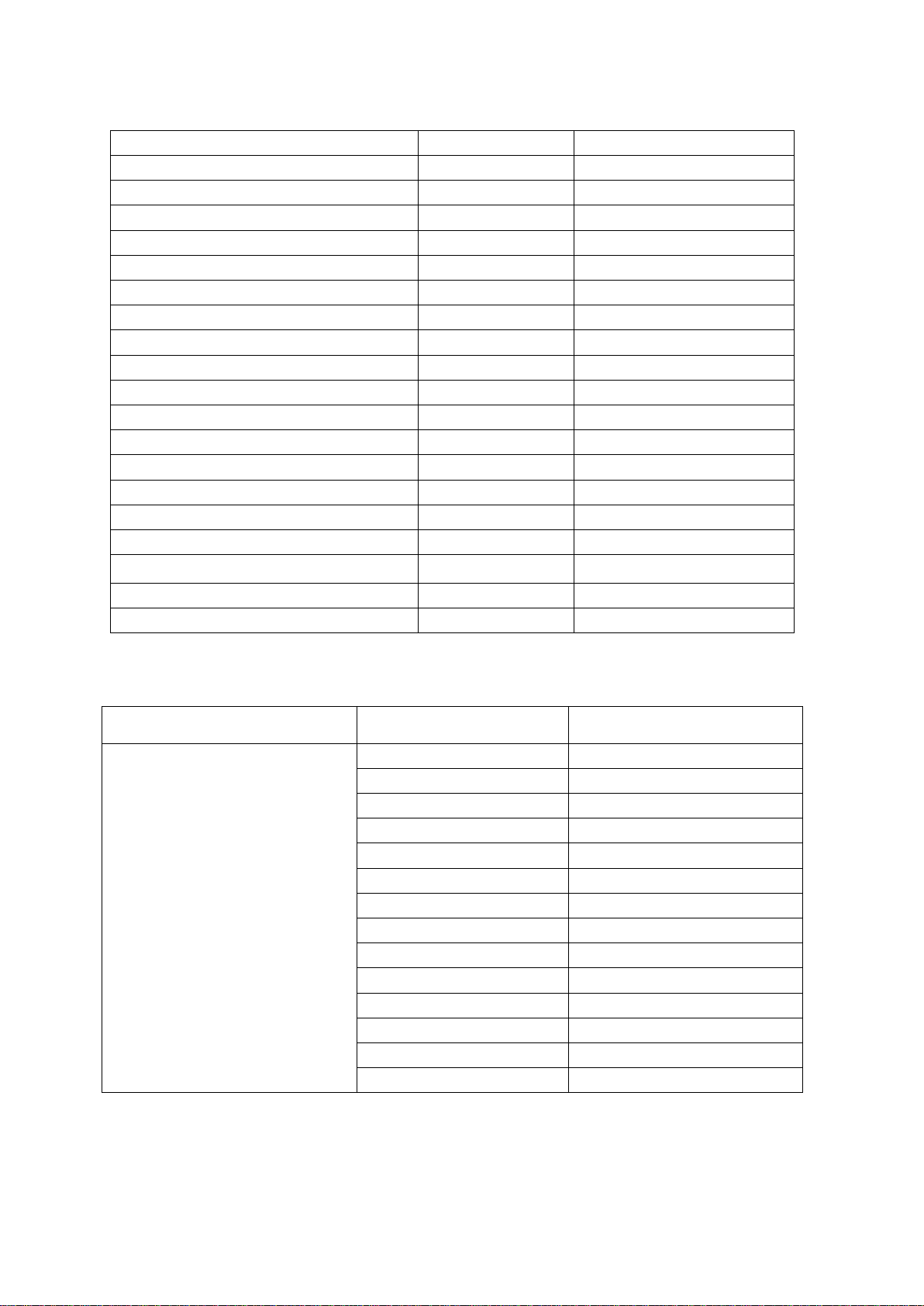
1-2 Parameters...................................................................................................................................3
1-3 Maintenance limit ..................................................................................................................... 3
Part II Dimension and Torque....................................................................................................................5
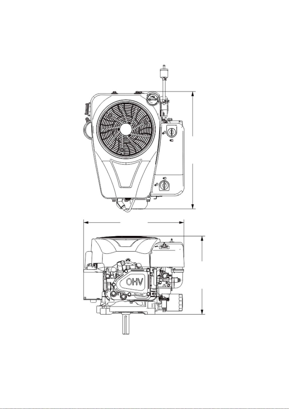
2-1 Dimensions of general-purpose gasoline engine ........................................................................... 5
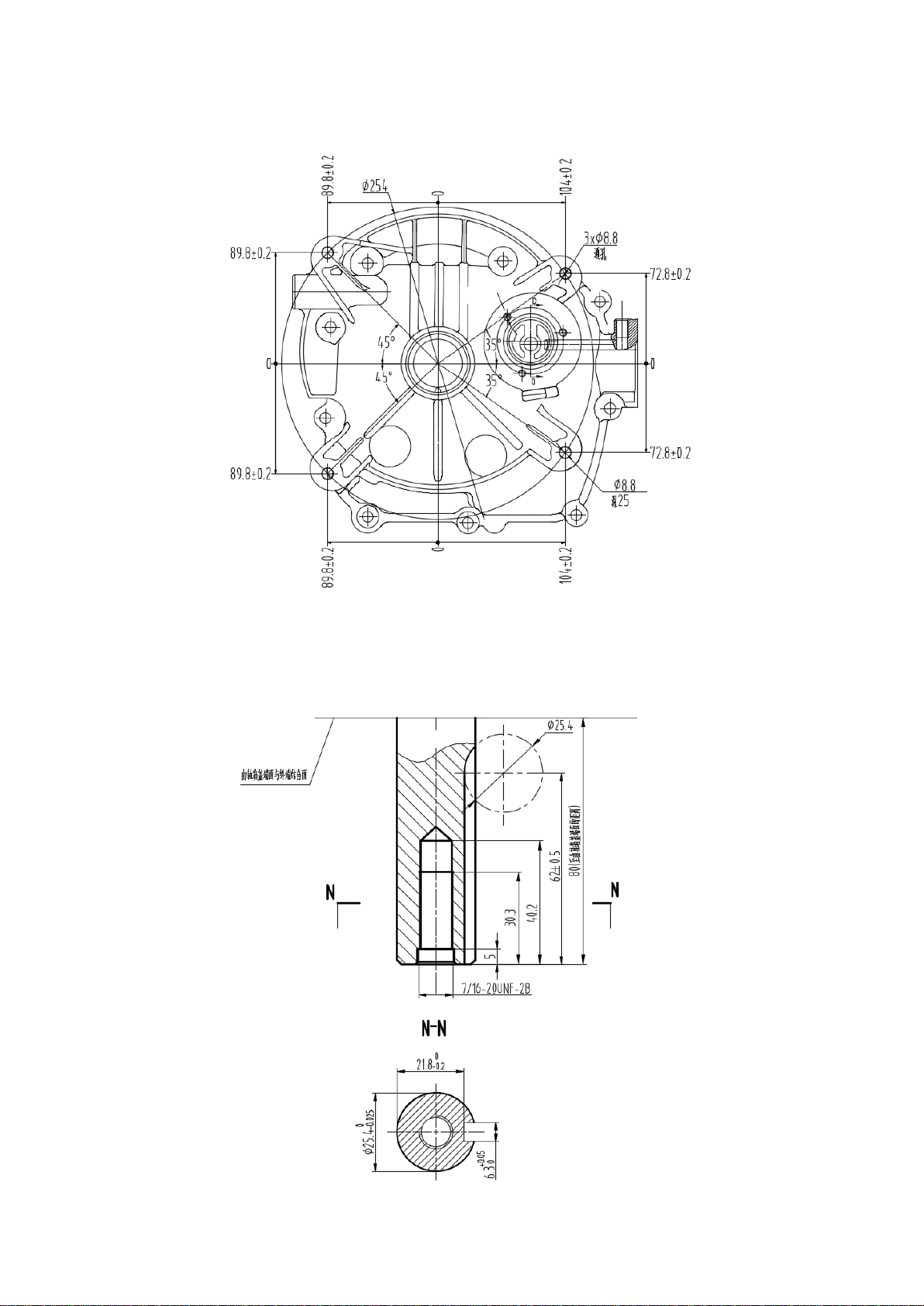
2-2 Locations of mounting holes........................................................................................................6
2-3 PTO installation drawing .............................................................................................................6
2-4 Torque parameters .......................................................................................................................7
2-5 Standard torque parameters..........................................................................................................7
Part III Maintenance...............................................................................................................................8
3-1 Maintenance list...........................................................................................................................8
3-2 Oil...............................................................................................................................................9
3-3 Air filter..................................................................................................................................... 10
3-4 Spark plug ................................................................................................................................. 11
3-5 Adjustment of valve clearance.................................................................................................... 13
3-6 Governor ................................................................................................................................... 14
Part IV Disassembly and Maintenance..................................................................................................... 15
4-1 Troubleshooting......................................................................................................................... 15
4-1-1 Start difficulty................................................................................................................. 15
4-1-2 Underpowered................................................................................................................. 16
4-1-3 Unstable speed................................................................................................................ 17
4-1-4 Unable to Ignite .............................................................................................................. 18
4-1-5 Overheating of general-purpose gasoline engine.............................................................. 18
4-1-6 Abnormal sound.............................................................................................................. 19
4-2 Pre-maintenance Preparations .................................................................................................... 19
4-2-1 Safety factors.................................................................................................................. 19
4-2-2 Special tools.................................................................................................................... 21
4-3 Disassembly chart...................................................................................................................... 22
4-4 general-purpose gasoline engine................................................................................................. 22
4-4-1 Muffler ........................................................................................................................... 22
4-4-2 Air filter.......................................................................................................................... 23
4-4-4 Carburetor....................................................................................................................... 26
4-4-5 Flywheel......................................................................................................................... 30
4-4-6 Ignition coil detection...................................................................................................... 31
4-4-7 Charging coil detection ................................................................................................... 32
4-4-8 Voltage regulating rectifier.............................................................................................. 33
4-4-9 Cylinder head/valve ........................................................................................................ 34
4-4-10 Crankshaft/Piston.......................................................................................................... 40
4-5 Electrical schematic diagram...................................................................................................... 48

2
Part I Introduction
1-1 Components of general-gasoline engine
Spark plug
Starter
motor
components
Voltage
regulator
Engine
outer
cover
Spark plug cap
Engine
dust cover
Air
filter
Secondary oil filter
Gasoline pump
component
Fuel filter
Oil level gauge

3
1-2 Parameters
Model
Specification parameters
RV550D
Length*width*height
480*406*315 (mm) (no muffler)
Net weight
32 kg
Type of gasoline engine
Horizontal single-cylinder, four-stroke,
overhead valve (OHV)
Air displacement
547 cm3
Cylinder diameter x stroke
94.5 mm × 78 mm
Theoretical maximum power
12.2 kW/3,600 r/min
Recommended service power
8.8 kw/2,700 r/min
Maximum torque
36.2 N·m/2,500 r/min
Fuel consumption
≥ 374 g/kW·h
Cooling system
Forced air cooling
Ignition system
Inductance type
Power output mode
Vertical axis output
1-3 Maintenance limit Unit: mm
Parts
Item
Standard
Service
limit
Gasoline
engine
Maximum speed without load
Idle speed
Cylinder pressure
3,000 ± 100 rpm
1,900 ± 100 rpm
≥ 1.05 Mpa/1,400 rpm
-
-
-
Cylinder
Cylinder inner diameter
94.5
94.665
Cylinder
head
Warping
--
--
Piston
Outer diameter of piston skirt
Piston-cylinder clearance
Inner diameter of piston pinhole
Outer diameter of piston pin
Piston-piston pin hole clearance
94.46-94.47
0.03-0.055
20.002-20.008
19.992-19.998
0.007-0.024
94.36
0.12
20.052
19.9
0.5
Piston ring
Piston ring side gap: Ring 2
0.02-0.07
0.135
Connecting
Inner diameter of small end
20.005-20.016
20.052

4
rod
Inner diameter of big end
Big-end oil-film clearance
Clearance of big end side
38.010-38.022
0.030-0.055
0.1-0.75
38.066
0.12
1.8
Crankshaft
Outer diameter of crankshaft
37.967-37.98
37.92
Air valve
Valve clearance
Intake
0.15-0.20
0.5
Exhaust
0.15-0.20
0.5
Outer diameter of
valve stem
Intake
6.563-6.575
6.418
Exhaust
6.548-6.56
6.375
Inner diameter of
Conduit
Intake/Exhaust
6.60-6.615
6.662
Width of valve seat
1
2.2
Free length of spring
39.5
38
Camshaft
Camshaft height
Intake
31.5
31.3
Exhaust
31.5
31.3
Outer diameter of
camshaft
14.966-14.984
14.916
Crankcase
cover
Inner diameter of camshaft carrier
15.0
15.2
Spark plug
Clearance
0.6-0.8
-
Spark plug
cap
Resistance
8 kΩ-12 kΩ
-
Ignition
coil
Air gap
(at the flywheel)
0.3~0.6 mm
-

5
Part II Dimension and Torque
2-1 Dimensions of general-purpose gasoline engine
480
406
315

6
2-2 Locations of mounting holes
2-3 PTO installation drawing

7
2-4 Torque parameters
Fastening position
Fastening part
Torque (N·m)
Oil drain plug
3/8-18NPTF
20 ± 2
Connecting rod bolt
M8 × 38
16 ± 1.5
Mounting bolt of governor gear
M6 × 14
10 ± 2
Closure bolt (special bolt)
M8 × 45
24 ± 2
Assembly of spark plug
M14 - 1.25
22 ± 2
Rocker arm shaft bolt
M8 × 1.25
24 ± 2
Valve locking nut
M6 × 0.75
10 ± 1
Cylinder head cover mounting bolt
M6 × 16
10 ± 2
Mounting bolt of breathing tank cover plate
M6 × 16
6 ± 1
Assembly of cylinder head
M10 × 60
45 ± 3
Assembly of cylinder head
M8 × 50
24 ± 2
Breathing plate combination
M4 × 10
1.5 ± 0.5
Starter motor components
M8 × 55
24 ± 2
Charging coil combination
M5 × 25
7 ± 1
Flywheel nut (cast iron flywheel)
M16 × 1.5
160 ± 10
Ignition coil mounting bolt
M6 × 25
10 ± 2
Air filter intake pipe
M6
10 ± 2
Mounting nut of governor bracket
M6
7 ± 1
Muffler components
M8
24 ± 2
Note: refer to the standard torque for the bolt, screw and nut without special provisions.
2-5 Standard torque parameters
Fastening part
Thread specification
Torque (N·m)
Bolts and nuts
5 mm bolt and nut
4.5-6
6 mm bolt and nut
8-12
8 mm bolt and nut
18-25
10 mm bolt and nut
29-34
12 mm bolt and nut
49-59
4 mm screw
1.5-2.6
5 mm screw
3.5-5
6 mm screw
7-11
5 mm flange bolt
3.6-6.9
6 mm screw
7-11
5 mm flange bolt
3.6-6.9
6 mm flange bolt
10-14
8 mm flange bolt
20-26
10 mm flange bolt
35-45

8
Part III Maintenance
3-1 Maintenance list
●The oil shall be replaced every 10 h if it is frequently operated under high
temperature or high load.
●The air filter element shall be cleaned every 10 h if it is frequently operated in
dusty or harsh environment; the air filter element shall be replaced every 25 h if
necessary.
●The maintenance shall be carried out on the basis of first come for the spot
inspection period and time.
●If the maintenance interval has expired, the maintenance shall be carried out
according to the above table as soon as possible.
Maintenance
period
Item
Every
time
1st month
or 10
hours at
the first
time
Every 3
months or
20 hours
Every 6
months or
50 hours
Every year
or 100 hours
Gasoline
engine oil
Check-fill
√
Replace
√
√
Air filter
element
Check
√
Clean
√
Replace
√
Spark plug
Clean-adjust
√*
Spark arrester
Clean
√
Valve
clearance**
Check-adjust
√
Fuel pipe
Check
Every two years (please replace it if necessary)
Cylinder head
and piston
Clear carbon
deposits**
Every 200 hours;
*The item shall be replaced if necessary;
**These items shall be maintained by the dealer authorized by our company, unless the user
has proper tools and maintenance capability.

9
3-2 Oil
The gasoline engine oil is the main factor affecting
the performance and service life of gasoline engine.
It is recommended not to use the oil including
additives and two-stroke engine oil, or the service life
of the gasoline engine will be shortened due to their
insufficient lubricating property.
The engine shall be powered off and placed on a
horizontal level during the inspection of the oil.
Oil capacity: RV550 1.5L
SAE10W-40 is the recommended general-purpose oil at common temperatures; the oil with
other stickiness could be used when the temperature in your area is within the range shown in
the chart.
Inspection steps:
a) Remove the oil level gauge and wipe off the oil.
b) Insert the oil level gauge into the filling inlet, don't twist it, check the oil level.
c) The oil level is low if no oil is on the oil level gauge, fill the recommended oil to 2/3 of
the grid mark of the oil level gauge.
d) Reinstall the oil level gauge.
Oil drain port
Oil level
lower limit
Oil level
upper limit
Environmental temperature
Temperature

10
Replacement of oil:
There is harmful substance in the waste oil, if the skin contact with the waste oil for
a long time, it may lead to skin cancer. Clean your hands thoroughly with soap and
water as soon as possible after contact with the waste oil.
In discharging, the waste oil shall be drained into a container, no pollution shall be
made to the environment.
a) Screw out the oil level gauge.
b) Tilt the gasoline engine to make the oil be drained from the oil hole.
3-3 Air filter
The gasoline engine's air filter shall be cleaned every 20 h or 3 months, and the air filter element
shall be replaced every 50 h. (Cleaning times shall be added in harsh environment, and
replacement shall be made if necessary)
Remove the air filter housing cover and take out the filter element.
Replace damaged filter element.
Clean the filter element before reuse
Cleaning of filter element:
Foam filter
element
Clean the filter element with solvent and dry it.
Impregnate the filter element into oil and squeeze out the excess oil. The filter element
shall be oily, but there shall be no dropping oil.
Air filter housing cover
Air filter element combination
Air filter intake pipe
assembly
Plug
Hexagon flange nut M6

11
Paper filter
element
Blast compressed air from inside or slightly knock it to remove the dust. It
shall be replaced in case of very dirty.
Be careful not to let dust enter the carburetor when wiping off the air filter cover
Reinstall the filter element into the housing and place the housing cover on.
3-4 Spark plug
a) Remove the spark plug cap and clean the debris around the spark plug.
b) Disassemble the spark plug with special socket and handle of the spark plug.
c) Check the spark plug visually, if there is obvious wear or damaged insulator, it shall be
replaced with a new one; if it is still operable, clean it with wire brush.
d) Measure the spark plug clearance with feeler gauge, the proper clearance shall be 0.60-0.80
mm; if adjustment is required, tap (when the clearance is large) it or gently pry up the
electrode with a straight screwdriver (the gap is too small).
Spark
plug
socket
Spark plug cap

12
e) In order to prevent disorderly thread, screw in the
spark plug with hand, tighten it with special socket, and then
tightly press the washer.
f) If a new spark plug is installed, an additional
1/2 turn shall be tightened after pressing the washer.
g) If a used spark plug is reinstalled, an
additional 1/8~1/4 turn shall be tightened after
pressing the washer.
Spark plug torque value: 22 ± 2 N·m
Spark plug model: F6RTC
The spark plug must be tightened properly, or it may be extremely hot and damages the
gasoline engine. The recommended spark plug or its equivalent products shall be used,
incorrect calorific value range of spark plug will cause damage to the gasoline engine.
Side electrode
0.60~0.80 mm
Spark plug cap
Spark plug

13
3-5 Adjustment of valve clearance
The valve clearance must be measured when the gasoline engine is cold.
a) Remove the bolts (M6×16), cylinder head
cover, gasket, spark plug cap and spark
plug in turns
The oil will overflow after removing the cylinder cover, wipe off the spilled oil.
b) Rotate the crankshaft slightly to make the
piston be at the top dead center of the
compression stroke, be careful the false
timing, (insert the screwdriver into the spark
plug hole to detect the height of the plug)
c) Loosen the valve lock with 10 mm wrench,
the spacing between the valve lock top surface
and the valve adjusting nut top surface shall
be about 3 mm
d) Put the 0.15 mm feeler gauge at the location
shown in the drawing
e) Tighten the valve lock with 14 mm wrench
or loosen the valve adjusting nut until there is a
resistance when moving the feeler gauge
f) Fix the 14 mm wrench, tighten the valve
Feeler gauge
Hexagon flange bolt
Spark plug
Cylinder head
cover gasket
Cylinder head
cover

14
lock with 10 mm wrench
Locking torque: about 8 N·m~12 N·m
g) Take out the 10 mm and 14 mm wrenches, measure the air valve clearance with the feeler
gauge slightly; if the clearance is too large or small, repeat the steps c~f;
h) Adjust the valve clearance of another air valve with the same method;
i) Power on the engine, observe whether the valve rocker is operated normally; if it is
abnormal, it indicates that the top dead center is false timing, turn the engine to true timing
and repeat the above steps.
j) Mount new gasket to make it tightly connect with the cylinder head.
k) Install the cylinder head cover, tighten 4 bolts according to specified torques.
Torque values: 10 ± 2 N·m
Standard value of valve clearance
Intake valve
0.10-0.15 mm
Exhaust valve
0.15-0.20 mm
Adjusting nut
Valve clearance
Tighten
Decrease
Loosen
Increase
Excessive gap: Late opening of intake and exhaust valves shortens the intake and
exhaust time, reduces the valve opening height, changes normal valve timing and
decreases the gasoline engine's power due to insufficient air intake and incomplete air
exhaust; additionally, it also increases the impact of valve system parts and accelerates
the wear.
Excessive little clearance: After the gasoline engine is operated, the part is heated and
expanded to push the valve open and make the valve close loosely, which will cause air
leakage, power reduction, and serious carbon deposition or burning on the sealing
surface of the valve, and even the valve strikes the piston.
3-6 Governor
Governor adjustment:
The machine speed under mower status has been adjusted before delivery, no adjustment shall

15
be done when using.
Part IV Disassembly and Maintenance
4-1 Troubleshooting
4-1-1 Start difficulty
Phenomenon
Cause
Remedy
Normal cylinder compression
Normal spark of spark plug
Abnormal fuel system
Impeded fuel flow or
no fuel flow
There is no fuel in fuel tank
Refuel
Clogged venthole of fuel tank cap
Dredge
Main measuring hole is
improperly adjusted or blocked
Re-adjust or clean, blow through
Float needle hole is blocked
Remove needle valve for repairing,
cleaning and blowing through
The floater is stuck or damaged
Repair the floater
Unobstructed
fuel flow
Fuel is too dirty or deteriorated
Replace fuel
There is water in fuel
Replace fuel
There is excessive fuel in the
cylinder
Drain the fuel, and wipe and dry
spark plug electrode
Fuel label is incorrect
Use according to specified label
Normal fuel supply system
Spark of HV
wire is normal
Spark plug is
poor
Electrode is dirty with carbon
deposit
Remove the dirt and carbon deposit
Insulator is damaged, electrode is
severe ablated
Replace the spark plug
Electrode gap is incorrect
Adjust electrode gap
HV wire has no
spark
Spark plug is
normal
HV line is damaged
Replace the HV line
Ignition coil is damaged
Replace the ignition coil
Magnet is demagnetized
Replace the flywheel
The clearance between ignition
coil and flywheel is abnormal
Adjust the clearance between ignition
coil and flywheel
Phenomenon
Cause
Remedy
Cylinder compression is poor
Normal fuel supply system
Normal spark of spark plug
Piston ring wear exceeds the limit
Replace complete set of new ring
Piston ring is broken
Replace complete set of new ring
Piston ring is stuck
Clear carbon deposit
The spark plug is not provided
with sealing gasket or is not
tightened
Mount the gasket and tighten it
Air leakage of joint face between
the cylinder body and cylinder
head
Check the flatness of joint face of
cylinder pad and cylinder body and
cylinder head
And tighten cylinder cover bolts
according to specified torque and
sequence

16
Valve leakage
Check valve clearance and valve
tightness, repair when necessary
If gasoline engine is still unable to be started, please send it to authorized dealer of the
Company for overhaul.
⚫Spark detection
Ensure that there is no spilled fuel outside the gasoline engine and the spark plug is
not soaked by fuel.
In order to prevent fire, keep sparks away from spark plug mounting hole.
When doing testing to the spark plug, it is strictly prohibited to hold the spark plug
with wet hand.
When operating, put the fuel switch in the "OFF" position, and drain off the fuel in the
carburetor.
Remove the spark plug cap and spark plug.
Pull the starter handle to release unburned gas out of the cylinder.
Assemble spark plug cap.
Ground the negative electrode (threaded part) of spark plug via the cylinder head, pull the
starter handle to observe the spark condition.
4-1-2 Underpowered
Phenomenon
Cause
Remedy
When raising
the throttle, the
speed increases
slowly, and the
speed decreases
or the engine
shuts down
Fuel supply
system
There is air in oil way or oil way
blockage
Exhaust and dredge oil way
Needle valve hole and the main hole
are blocked in the carburetor
Clean, and blow through
Fuel tank switch is clogged
Clean and replace damaged
part
Spark plug
Ignition coil
secondary cable

17
when it is
serious
Combustion-chamber deposit
Clear carbon deposit
Carbon deposit in the muffler and
exhaust pipe
Clear carbon deposit
Blockage of air filter
Clean filter element
Leakage of air intake system
Repair or replace
Poor
compression
Wear of piston, cylinder and piston
ring
Replace worn parts
Valve clearance is excessive
(excessive little)
Readjust
Valve seal is not sealed tightly
Repair
⚫Cylinder pressure inspection
Please send to the authorized dealer of the Company for repair.
4-1-3 Unstable speed
Phenomenon
Cause
Remedy
There is
knocking noise
in gasoline
engine
Excessive wear of piston, cylinder and
piston ring
Replace worn parts
Excessive wear of piston pin and pin hole
Replace the piston or piston pin
Excessive wear of small end of
connecting rod
Replace the connecting rod
Deflagration
Gasoline engine overheating
Find the cause and eliminate
Combustion-chamber deposit
Clear carbon deposit
Unqualified gasoline
Replace qualified gasoline
Misfire of
gasoline engine
There is water in float chamber
Clean the float chamber
Electrode clearance of spark plug is
improper
Adjust electrode gap
Ignition coil failure, etc.
Check and replace damaged parts
Cylinder
pressure gauge
Table of contents
Other Rato Portable Generator manuals
Popular Portable Generator manuals by other brands

Clarke
Clarke PG9500ADVES Operation & maintenance instructions

Haussmann
Haussmann PGR-6000 Silent Operation manual

GT POWER
GT POWER GT7005EFi operating instructions

Power
Power SUA6900 owner's manual

Chicago Electric
Chicago Electric 96898 Set up and operating instructions

Daewoo
Daewoo DAGFS-15AC user manual