www.raycap.com
©Raycap • All rights reserved
320-1261 Rev.C
Page 4 of 24
3315-ALM-RS485 INSTALL INSTRUCTIONS
1.2 Warnings
Before using the product, read all instructions and cautionary markings on the product and on
any equipment connected to the product.
CAUTION – Unless otherwise noted, product usage that is not recommended or sold by the
product manufacturer can result in risk of re, electric shock, or injury to persons.
CAUTION – Do not operate the product if it has been damaged in any way. Return damaged
products to their manufacturer for repair or replacement.
ATTENTION – Electrostatic sensitive devices. ESD mitigative procedures, such as wearing
wriststraps are to be used during installation and maintenance.
2. Introduction
In a split Radio Base Station (RBS) architecture the typical RBS consists of a Base Band Unit
(BBU) and Remote Radio Heads (RRH) connected by cabling. Power to the RRH is provided
through copper cables traveling from the base station to the top of the tower or roof top. This
creates a conductive path, making the active equipment at the top and the base of the site
vulnerable to damage by direct lightning strikes. Protection systems installed in front of both
the BBU and the RRH must be able to withstand direct lightning currents in order to protect
the sensitive equipment. Raycap’s RRH solutions featuring Strikesorb® SPD technology
signicantly enhance the reliability & availability of the RRH site by providing superior
electrical protection at the RRH and BBU, and also enable exible ber optic and power cable
management solutions.
The 3315-ALM-RS485 is suitable for installation for Network Telecommunications Facilities,
(Central Ofce), Outside Plant (Remote Termainal Facilities), and locations where the NEC
applies (Customer Prem Locations).
3.1 Prerequisites
Installers of Raycap’s RRH surge protective and ber/power management solutions must be
industry professionals who have attended training on the proper installation of the equipment
by Raycap and/or the mobile operator. Installers are required to read this installation guide
thoroughly prior to installation of the Raycap RRH protection equipment.
Installers shall obey all general and regional installation and safety regulations related to
work on high voltage installations, as well as regulations covering correct use of tools and
personal protective equipment. Use this equipment only for the purpose specied by the
manufacturer. Do not carry out any modications or t any parts that are not recommended by
the manufacturer. This could cause electric shock or other injuries.
3.2 Required Tools
#2 Phillips head screwdriver
ESD Strap
Torque wrench
¼” Nut Driver
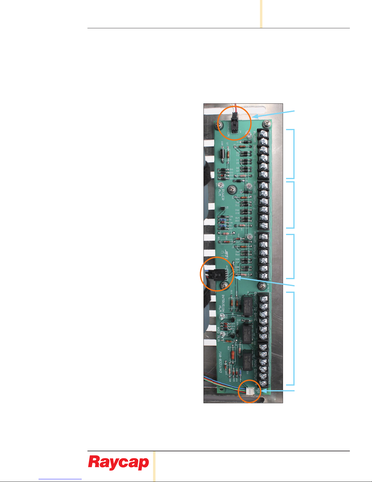
3.3 Kit Contents
Alarm/Voltmeter PCB Assembly
Anti-Static Wrist Strap
Installation Instructions
For conditions other than those described above, please contact a Raycap Account
Representative at +1 (208) 777-1166, (800) 890-2569, info@raycap.com, or www.raycap.com