Raycap RCMDC-6627-PF-48 User manual

Installation Instructions:
RCMDC-6627-PF-48
INSTALL INSTRUCTIONS RCMDC-6627-PF-48
www.raycap.com


www.raycap.com
©Raycap • All rights reserved
320-1204 Rev.E
Page 1 of 38
INSTALL INSTRUCTIONS RCMDC-6627-PF-48
Contents
1. Copyright 2
1.1 Disclaimer 2
1.2 Warnings 2
2. Introduction 3
3. Overvoltage Protection Package Contents 3
3.1 Prerequisites 3
3.2 Required Tools and Supplies 3
3.3 General Install Information 4
4. Procedure 5
4.1 Mounting Procedures 5
5.1 Gland/InsertDenitions 5
6.1 Pre-wiring Preparation Procedure 6
7.1 Cable Installation Instructions 8
8.1 Installing Hybrid Cable-Power (In) 9
9.1 Installing Hybrid Jumper Cable-Power (Out) 10
10.1 Installing Ground Cable 11
11.1 Alarm Wiring 12
12.1 Installing Hybrid Cable-Fiber (In) 24
13.1 Installing Hybrid Cable-Fiber (Out) 25
14.1 Installation Complete. Closing and Securing Unit. 27
(Optional)
A. Addendum: High Power Wire Bridge Kit for Model RCMDC-6627-PF-48 29

RCMDC-6627-PF-48 INSTALL INSTRUCTIONS
www.raycap.com
©Raycap • All rights reserved
320-1204 Rev.E
Page 2 of 38
1.0 Copyright
©Raycap, Inc. 2018 - All Rights Reserved
1.1 Disclaimer
The information in this document is subject to change without notice and describes only the product
dened in the introduction of this documentation. This documentation is intended for the use of
Raycap customers only for the purposes of the agreement under which the document is submitted,
and no part may be used, reproduced, modied or transmitted in any form or means without the prior
written permission of Raycap. The documentation has been prepared to be used by professional
and properly trained personnel, and the customer assumes full responsibility when using it. Raycap
welcomes customer comments as part of the process of continuous development and improvement
of the documentation.
This product is suitable for OSP. (Outside Plant)
Raycap has made all reasonable efforts to ensure that the instructions contained in this document
are adequate and free of material errors and omissions. Raycap will, if deemed necessary, explain
issues which may not be covered by this document.
The contents of this document are subject to revision without notice due to continued progress in
methodology, design and manufacturing. Raycap shall have no liability for any error damage of any
kind resulting from the use of this document.
1.2 Warnings
Please read this manual prior to use to become familiar with the product’s numerous features and
operating procedures. To maintain the maximum degree of safety, follow the sequences as outlined.
Before using the product, read all instructions and cautionary markings on the product and on any
equipment connected to the product.
CAUTION – Unless otherwise noted, product usage that is not recommended or sold by the product
manufacturer can result in risk of re, electric shock, or injury to persons.
CAUTION – Do not operate the product if it has been damaged in any way. Return damaged
products to their manufacturer for repair or replacement.
CAUTION – Do not disassemble the product as incorrect reassembling can risk electrical shock or re.
WARNING – Disconnect or disable the DC power source to the product prior to beginning its
installation. Ensure that the DC power source to the product remains de-energized until the
completion of the installation and after all connections have been veried to be correctly congured.
ATTENTION – Electrostatic sensitive devices. ESD mitigative procedures, such as wearing
wriststraps are to be used during installation and maintenance.
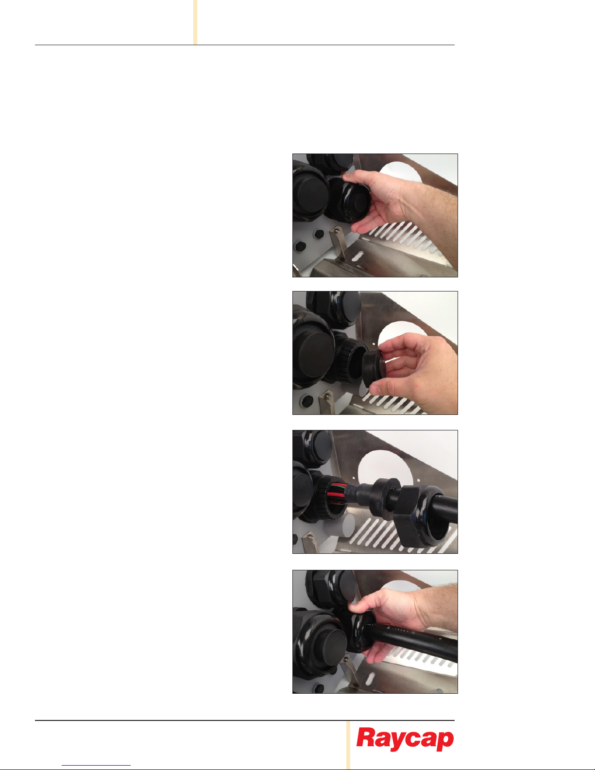
ATTENTION – Installation of the hybrid cable requires an approved hanger to be used no more than 3
feet from the entrance of the Raycap unit. Refer to cable manufacturer’s instructions for proper hardware.
CAUTION – Do not bend ber-optic cables beyond their minimum bend radius. Bending the cables
beyond their minimum bend radius can damage the cables and cause problems that are difcult to
diagnose.
CAUTION – Do not let ber-optic cables hang free from the connector. All ber must be secured
against movement in wind while maintaining enough slack to prevent any tension along the run. Do
not allow fastened loops of cables to dangle, which stresses the cables at the fastening point.
WARNING – Do not look directly into a ber-optic transceiver or into the ends of ber-optic cables.
Fiber-optic transceivers and ber-optic cables connected to transceivers emit laser light that can
damage your eyes.

www.raycap.com
©Raycap • All rights reserved
320-1204 Rev.E
Page 3 of 38
INSTALL INSTRUCTIONS RCMDC-6627-PF-48
WARNING: Do not stare into the laser beam or view it directly with optical instruments even if the interface
has been disabled.
1. If the ber-optic cable connector is covered by a rubber safety cap, remove the cap. Save the cap.
2. If the optical transceiver is covered by a rubber safety cap, remove the cap. Save the cap.
3. Prior to connecting the ber to the device, clean it using proper industry accepted cleaning methods.
4. Insert the cable connector into the optical transceiver.
5. Secure the cables so that they are not supporting their own weight. Place excess cable out of the way in
a neatly coiled loop. Placing fasteners on a loop helps cables maintain their shape.
For conditions other than those described above, please contact a Raycap Account Representative at
+1 (208) 777-1166, (800) 890-2569, info@raycap.com, or www.raycap.com
Thank you for choosing quality products from Raycap.
2.0 Introduction
In a split Radio Base Station (RBS) architecture the typical RBS consists of a Base Band Unit (BBU) and
Remote Radio Heads (RRH) connected by cabling. Power to the RRH is provided through copper cables
traveling from the base station to the top of the tower or roof top. This creates a conductive path, making
the active equipment at the top and the base of the site vulnerable to damage by direct lightning strikes.
Protection systems installed in front of both the BBU and the RRH must be able to withstand direct lightning
currents in order to protect the sensitive equipment.
Raycap’s RRH solutions featuring Strikesorb® SPD technology signicantly enhance the reliability &
availability of the RRH site by providing superior electrical protection at the RRH and BBU, and also enable
exible ber optic and power cable management solutions.
3.0 Overvoltage Protection Package Contents
• One (1) Enclosure including the SPDs, cable glands, the DC distribution and
ber management parts.
• Incorporated Mounting bracket and related accessories.
• Mounting hardware accessories (bolts, washers and nuts)
3.1 Prerequisites
This document describes how to install the RCMDC-6627-PF-48 on-site and how to mount, and connect it to
external interfaces.
Installers of Raycap’s RRH surge protective and ber/power management solutions must be industry
professionals who have attended training on the proper installation of the equipment by Raycap and/or the
mobile operator. Installers are required to read this installation guide thoroughly prior to installation of the
Raycap RRH protection equipment.
Installers shall obey all general and regional installation and safety regulations related to work on high
voltage installations, as well as regulations covering correct use of tools and personal protective equipment.
Use this equipment only for the purpose specied by the manufacturer. Do not carry out any modications or
t any parts that are not recommended by the manufacturer. This could cause electric shock or other injuries.
3.2 Required Tools & Supplies
Wire cutter
Wire strippers
Flat head screwdriver
Small at head screwdriver
Torque wrench
Cross head screwdriver
Adjustable wrench
5/32" Hex key/driver

RCMDC-6627-PF-48 INSTALL INSTRUCTIONS
www.raycap.com
©Raycap • All rights reserved
320-1204 Rev.E
Page 4 of 38
3.3 General Install Information
Whenever installing a RCMDC-6627-PF-48 at the top and connecting it at the base to a
RCMDC-4520-RM-48x, RCMDC-2260-RM-48, or a RCMDC-3315-PF-48, the (4520),
(2260) or (3315) should include a retrotted alarm board to communicate properly to the
newly installed (6627).
Whenever installing a (6627) at the tower top, the alarm board rotary switch should be in
the default #1 position.
Any unit installed at the base connected to a (6627) at the top, whether it be a (4520),
(2260) retrot, (3315) retrot, or another (6627) will be at rotary switch position 2. If there
are subsequent units daisy chained at the base they will take the next number on the rotary
switch #3 and on as more units are daisy chained together. As many as 4 units can be
daisy chained together the last being at rotary switch #5 position.

www.raycap.com
©Raycap • All rights reserved
320-1204 Rev.E
Page 5 of 38
INSTALL INSTRUCTIONS RCMDC-6627-PF-48
• Pole Mount
• Unistrut
• Monopole
Procedure
Mounting Procedures
4.1 A mounting base is delivered with the
unit. The base allows either wall/ladder
or pole mounted installation. See picture
to identify the holes for each installation
method.
4.2 Option 1: Pole Mount
Using supplied hardware, mount Bracket
to 2" to 4" diameter pole.
4.3 Option 2: Unistrut
4.4 Option 3: Monopole
Use 1" stainless steel bands
(not supplied) through slots on bracket
to mount to Monopole.
Gland/InsertDenitions
5.1 See picture to identify
Base Gland Assembly
Denitions.
Assembled in unit as shipped:
Qty Connector
Size
Pos Insert
P/N
Insert
Hole
Cable
Type
2 M75 A 190-0760 42mm 6x12 RL
4 M75 B 190-0738 3x
16.5mm 1x2
Included in kit shipped with unit:
Qty
Connector
Size
Insert
P/N
Insert
Hole
Cable
Type Purpose Pos
2 M75 190-0760 42mm 6x12 RL 2 glands t 1 each 6/12 Hyb B
2 M75 190-0747 2x 24.5mm 2x12 DC 2 glands t 2 each #6 12 cond DC B
1 M75 190-0905 2x 10.5mm 2x12 Fiber 1 gland t 2 x 12 ber trunk B
1 M75 190-0912 2x 9.5mm 2 ETH 1 gland ts 2 ethernet cable B
A
B
B
B
A
B

RCMDC-6627-PF-48 INSTALL INSTRUCTIONS
www.raycap.com
©Raycap • All rights reserved
320-1204 Rev.E
Page 6 of 38
Pre-wiring Preparation Procedure
6.1 Ensure the lanyard from enclosure lid to
enclosure base is secure.
6.2 Open up clamps on all sides of the
enclosure cabinet by lifting the hinged
clamp tabs.
6.3 Remove enclosure lid.

www.raycap.com
©Raycap • All rights reserved
320-1204 Rev.E
Page 7 of 38
INSTALL INSTRUCTIONS RCMDC-6627-PF-48
6.4 To access power and ber connections,
unclasp 1/4 turn latches, then fold down ber tray.
6.5
Return
Connection
Fiber Connection
Panel
Fiber
Management
Fiber
Connectors
Fiber Panel
Label
Alarm
Board
Alarm
Connector
Alarm
Connector
Mode Select
Switch
Moisture
Sensor
Intrusion
Sensor
Strikesorb
Module
-48V
Connection
Voltage
Monitor
Return
Connection
Hybrid Trunk
Ground Points
-48V
Connection

RCMDC-6627-PF-48 INSTALL INSTRUCTIONS
www.raycap.com
©Raycap • All rights reserved
320-1204 Rev.E
Page 8 of 38
Cable Installation Instructions
7.1 At the base of the OVP boxes there are cable glands
that provide weatherproong for the enclosure.
The following steps will show how to install the
Hybrid cable properly.
7.2 Remove compression nut.
7.3 Remove center insert from cable gland.
7.4 Slide compression nut and insert over
the cable breakout. Be careful not to
damage the ber connectors. Insert
needs to be 1" behind heat shrink tube.
7.5 Carefully feed ber and power
conductors into the OVP box and
tighten the compression nut.
Torque: approximately 44 in-lbs

www.raycap.com
©Raycap • All rights reserved
320-1204 Rev.E
Page 9 of 38
INSTALL INSTRUCTIONS RCMDC-6627-PF-48
Installing Hybrid Cable-Power (In)
8.1 For more access to the printed circuit
boards, the Fiber Panel can be
temporarily removed.
8.2 Attach secure lanyard to unit base.
See photographs below.
8.3 Feed Hybrid trunk through Insert.
8.4 Feed enough of the cable to strip and
connect to power connectors.
8.5 Connect wires according to the
Verizon Wireless established
color guide.
Note:
Bring all cables through cable glands.
Ensureallberisseparatedandoutof
thewayduringcopperwireinstallation.
Toassistineaseofwiring,proceed
bywiringinthefollowingorder:
1st: OVP #1 and OVP #7
2nd: OVP #2 and OVP #8
3rd: OVP #3 and OVP #9
4th: OVP #4 and OVP #10
5th: OVP #5 and OVP #11
6th: OVP #6 and OVP #12
Torque: 40 in-lbs (10-6 AWG)
-48V
Return 1 7
2 8
3 9
4 10
5 11
6 12
Circuit IdenticationColor -48V RTN
1, 7 Blue
2, 8 Violet
3, 9 Green
4, 10 Brown
5, 11 Yellow
6, 12 White

RCMDC-6627-PF-48 INSTALL INSTRUCTIONS
www.raycap.com
©Raycap • All rights reserved
320-1204 Rev.E
Page 10 of 38
Installing Hybrid Jumper Cables-Power (Out)
9.1 Feed Hybrid jumpers through insert.
9.2 Feed enough of the cable to strip and
connect to power connectors.
1 7
2 8
3 9
4 10
5 11
6 12
1 7
2 8
3 9
4 10
5 11
6 12
9.3 Connect wires according to the
Verizon Wireless established
color guide.
Note:
Toassistineaseofwiring,proceed
bywiringinthefollowingorder:
1st: OVP #1 and OVP #7
2nd: OVP #2 and OVP #8
3rd: OVP #3 and OVP #9
4th: OVP #4 and OVP #10
5th: OVP #5 and OVP #11
6th: OVP #6 and OVP #12
Torque: 40 in-lbs (10-6 AWG)
Jumpers 1-6 installed (Hybrid Trunk not shown for clarity) Jumpers 1-12 installed
-48V
Return

www.raycap.com
©Raycap • All rights reserved
320-1204 Rev.E
Page 11 of 38
INSTALL INSTRUCTIONS RCMDC-6627-PF-48
Installing Ground Cable
10.1 There are two grounding placement
options available. See below.
Optional Cable GroundsMain Ground
Hybrid Trunk
Ground Points

RCMDC-6627-PF-48 INSTALL INSTRUCTIONS
www.raycap.com
©Raycap • All rights reserved
320-1204 Rev.E
Page 12 of 38
11.0 Alarm connections for RCMDC-6627-PF-48
11.1 Installing Alarm Wiring for RCMDC-6627-PF-48 Tower TopConguration
11.2 Installing Alarm Wiring for RCMDC-6627-PF-48 BaseConguration
Alarm Output to BTS
(not used in Tower Top Conguration)
Alarm Output to BTS
(dry contact outputs for Intrusion, H2O, and Power)
Rotary Switch
(·)& 1 are identical in functionality, therefore
either may be selected for tower top mode
Rotary Switch
Base mode operation. Place rotary switch to position “2”
which corresponds to base mode address “0”
If in daisy chain conguration, place selector switch to
the next base mode address
Tower Communication (D2)
Tower Top RS485 communication output to base,
2-twisted pair (4 wires total)
Base Communication (D2)
Base RS485 communication input from tower, 2-twisted pair
(4 wires total)
VBoost Input
(not used in Tower Top Conguration)
VBoost Input
Optional ethernet daisy chain input
VBoost Output
(not used in Tower Top Conguration)
VBoost Output
Optional ethernet output to daisy chain / VBoost
Tower Communication (D1):
Tower Top RS485 communication output to base,
2-twisted pair (4 wires total)
Base Communication (D1):
Optional RS485 daisy chain input

www.raycap.com
©Raycap • All rights reserved
320-1204 Rev.E
Page 13 of 38
INSTALL INSTRUCTIONS RCMDC-6627-PF-48
Push Button
Switch
Power/H2O/Intrusion
Alarm Indicators
LED Display
Base Unit:
As you scroll through by pressing the push button
switch, the unit will go through the status of all 12
circuits (upper and lower).
Note: As the display is a single numeric value,
it will go through 1-9 and A,b,C, which are place
holders for 10, 11, and 12.
(U1, L1, U2, L2,...U9, L9, UA, LA, Ub, Lb, UC, LC)
During normal operation, the display will show the
voltage of selected circuit.
Top Unit:
The top unit will only display its own status.
Reverse Polarity Short CircuitLow Voltage
(less than 35V)
Left Dot Blinking:
(receiving
daisy chain data)
Right Dot Blinking:
(receiving
tower top data)
Tower Top Unit
(both dots blink
indicating transmission)
Circuit status messages:
Base Unit: Tower Top Unit:
11.3 Voltage Display and Push Button Switch
Right Dot:
Flashing every 1
second, proper
communication
is established.
Flashing every 3
seconds, there
is a communica-
tion error.
Flashing every
1 second,
proper com-
munication is
established.

RCMDC-6627-PF-48 INSTALL INSTRUCTIONS
www.raycap.com
©Raycap • All rights reserved
320-1204 Rev.E
Page 14 of 38
11.4 Alarm connections for
RCMDC-2260-RM-48RetrotAlarmBoard
Alarm Output to BTS
(dry contact outputs for
Power, H2O, and Intrusion)
Base Communication (D2)
Base RS485 communication
input from tower,
2-twisted pair
(4 wires total)
Mode Select Switch
Base mode operation. Place
rotary switch to position “2”
which corresponds to base mode
address “0”
If in daisy chain conguration,
place selector switch to the next
base mode address
VBoost Input
Optional ethernet daisy chain input
VBoost Output
Optional ethernet output to
daisy chain / VBoost
(not used)
(not used)
(not used)

www.raycap.com
©Raycap • All rights reserved
320-1204 Rev.E
Page 15 of 38
INSTALL INSTRUCTIONS RCMDC-6627-PF-48
11.5 Alarm connections for
RCMDC-4520-RM-48x Alarm Board
Alarm Output to BTS
(dry contact outputs for
Power, H2O, and Intrusion)
Base Communication (D2)
Base RS485 communication input from
tower top #2, 2-twisted pair (4 wires total)
Base Communication (D1)
Base RS485 communication input from
tower top #1, 2-twisted pair (4 wires total)
Address Select Switch
Place rotary switch to position “0”
which corresponds to
base address “0”
If in daisy chain conguration,
place selector switch to the next
base address
VBoost Input
Optional RS485 daisy chain input.
Remote connection point
located on back of unit.
Blue cable is NOT to be removed,
see page 14 for connection location
VBoost Output
Optional RS485 output to
daisy chain / VBoost.
Remote connection point
located on back of unit.
Blue cable is NOT to be removed,
see page 14 for connection location

RCMDC-6627-PF-48 INSTALL INSTRUCTIONS
www.raycap.com
©Raycap • All rights reserved
320-1204 Rev.E
Page 16 of 38
Note:
Selector switch set to
“•” or ”1” for Tower Top mode
Note:
Selector switch set to
“0” for Base address “0”
Alarm
Outputs
to BTS
11.6 StandardBase/TowerConguration.
(1) RCMDC-6627-PF-48 unit at the tower top and (1) RCMDC-4520-RM-48x unit at the base.

www.raycap.com
©Raycap • All rights reserved
320-1204 Rev.E
Page 17 of 38
INSTALL INSTRUCTIONS RCMDC-6627-PF-48
Alarm
Outputs
to BTS
Tower-Base
communication
Note:
Selector switch set to
“•” or ”1” for Tower Top mode
Note:
Selector switch set to
“2” for Base mode
address “0”
Optional
Output to
VBOOST
Tower Top Unit
Base Unit
11.7 StandardBase/TowerConguration.
(1) RCMDC-6627-PF-48 unit at the tower top and (1) RCMDC-6627-PF-48 unit at the base.

RCMDC-6627-PF-48 INSTALL INSTRUCTIONS
www.raycap.com
©Raycap • All rights reserved
320-1204 Rev.E
Page 18 of 38
Tower-Base
communication
Note:
Selector switch set to
“•” or ”1” for Tower Top mode
Note:
Selector switch set to
“2” for Base mode
address “0”
Daisy Chain Output
Alarm
Outputs
to BTS
Daisy Chain
Output to next
Base unit
Tower-Base
communication
Note:
Selector switch set to
“•” or ”1” for Tower Top mode
Note:
Selector switch set to
“3” for Base mode
address “1”
Daisy Chain Input
11.8 DaisyChainConguration.
(2) RCMDC-6627-PF-48 units at the tower top and (2) RCMDC-6627-PF-48 units at the base.
Tower Top Unit #1
Base “0”
Table of contents
Other Raycap Surge Protector manuals