manuals.online logo
Brands
  1. Home
  2. •
  3. Brands
  4. •
  5. Raychem
  6. •
  7. Control Unit
  8. •
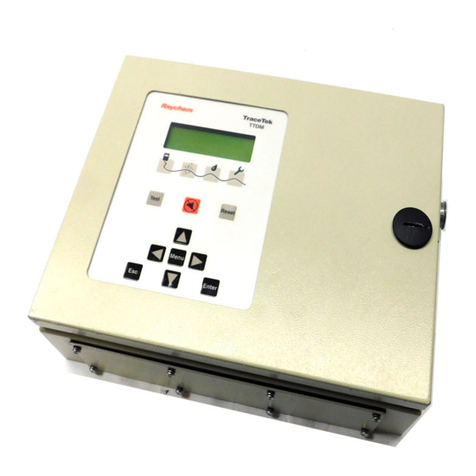
  9. Raychem TraceTek TTDM User manual

Raychem TraceTek TTDM User manual

RTraceTek
TTDM UI Software
EPROM Replacement
General Information
These instructions detail the steps to replace a Tracetek TTDM
User Interface EPROM (Erasable Programmable Read Only
Memory) using a TTDM-UI EPROM version 1.05 or higher. Once
the new EPROM has been installed, the TTDM should be fully
functional and will not need re-calibration. However, settings
changed from the factory defaults (e.g. Units, Password,
Sensitivity) and events history prior to EPROM replacement will
be lost.
Note: It is recommended that the events history be printed out
or downloaded through the serial port (or recorded in some other
manner) before the EPROM is replaced.
Important: The TTDM is an electronic unit. During installation,
take the following precautions to avoid damage to the electronic
components:
• Handle with care, avoid mechanical damage.
• Keep the electronics dry.
• Avoid exposure to static electricity; wear a well grounded
(earthed) wrist strap.
• If handling circuit boards, hold them by their edges to avoid
physical contact with electronic components.
• Avoid contamination with metal filings, liquids, or other foreign
matter.
Important: The EPROM is electrostaticly sensitive. Follow
these extra precautions to avoid damage:
• While replacing the EPROM, work on a grounded (earthed)
surface.
• Wear a well grounded (earthed) wrist strap when handling an
EPROM.
• Store an EPROM only on or in antistatic materials.
Tools required:
• Phillips (cross-head) screwdriver
• Flat-head screwdriver
Tools recommended:
• CMOS safe DIP IC extractor tool
• IC insertion tool for 24 and 28 pin DIP ICs
Refer also to
TTDM TraceTek Leak Detection and Location
Module Installation Instructions
(Raychem literature number
H55471).
Installation Instructions
Follow these steps to replace the TTDM User Interface EPROM:
1. WARNING: Shock hazard.
Disconnect power to TTDM before opening enclosure door.
2. Open the enclosure door using a flat-blade screwdriver or
coin.
Note: Put on a well grounded (earthed) wrist strap before
proceeding.
3. Disconnect the 26 pin ribbon cable from the User Interface
board on the door; spread the retaining ears on the cable
connector to release it.
4. Remove the four Phillips (cross-head) screws that secure the
User Interface board to the display plate.
5. Lift the User Interface (UI) board off the 16 pin connector at
the top of the door and remove the 12 pin ribbon cable at the
left side of the UI board.
Ribbon
cable
Screws
Installing the TTDM User Interface EPROM
Installation Instructions for TTDM UI Software EPROM Replacement
6. Put the UI board on a flat surface, turn it over, and locate the
28 pin EPROM chip (item U11) at its lower right corner. The
EPROM has a paper label bearing the following information:
Part ID: TTDM-UI or RC285067
Version: V 1.xx
Release date: 1/12/96 (or later)
7. Using a CMOS safe DIP IC extractor tool or small flat blade
screwdriver carefully pry the EPROM chip up and remove it
from its socket. Store this EPROM on or in antistatic material.
8. Orient the new EPROM with its socket, with the notched end
toward the bottom of the board (i.e. notched end of EPROM
aligned with notched end of socket). Make sure that all pins
are aligned with their sockets and (using an IC insertion tool
if available) press the chip into its socket. Visually inspect to
ensure all pins are properly seated.
9. Position the UI board on the enclosure door and reconnect
the 12 pin ribbon cable at left of the display. Align the UI
board and press it into the 16 pin connector from the LCD
display.
10. Fasten the UI board to the display plate with the four Phillips
(flat-head) screws; the screws should be snug, but do not
overtighten. Reconnect the 26 pin ribbon cable to the UI
board.
11. With UI versions 1.05 and higher, the TTDM automatically
reconfigures with the new software when the TTDM is first
powered after an EPROM replacement. If for some reason
an EPROM with an earlier UI software version is installed,
the TTDM must be manually reconfigured; consult the
factory.
12. Close and latch the enclosure, and reconnect power to the
TTDM. The TTDM starts up with factory default settings,
which include the password 0010.
13. Please return the old EPROM to Tracetek Products for
recycling; use the package in which the new EPROM
was supplied.
EPROM
Notched
end
User
Interface
Board
Belgium
NV Raychem SA
Diestsesteenweg 692
3010 Kessel-Lo
Tel (32) 16/351-800
Fax (32) 16/351-797
Korea
Raychem Korea Limited
831-45 Yeuksam-Dong
Kangnam-Ku
Seoul 135
Tel (82) 2/557-7752
Fax (82) 2/558-5765
United Kingdom
Raychem Ltd.
Faraday Road
Dorcan, Wiltshire SN3 5HH
Tel (44) 1793/572-663
Fax (44) 1793/572-629
United States
Raychem Corporation
Commercial & Industrial
Infrastructure Division
300 Constitution Drive
Menlo Park, CA 94025-1164
Tel (800) 545-6258
Fax (800) 611-2323
www.raychem.com
© 1996 Raychem Corporation Printed in USA H55875 10/96 TraceTek is a trademark of Raychem Corporation.
R
Installing the TTDM User Interface EPROM (continued)
LCD Connector
Ribbon
cable
Display
Plate
User
Interface
Board

Other Raychem Control Unit manuals

Raychem nVent RMM2-E User manual

Raychem

Raychem nVent RMM2-E User manual

Raychem EMDR-10 User manual

Raychem

Raychem EMDR-10 User manual

Raychem VIA-DU-20 User manual

Raychem

Raychem VIA-DU-20 User manual

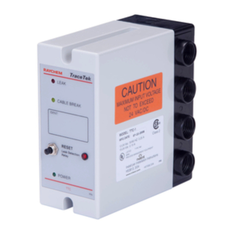
Raychem TRACETEK TTC-1 Manual

Raychem

Raychem TRACETEK TTC-1 Manual

Raychem TraceTek TTDM-2 User manual

Raychem

Raychem TraceTek TTDM-2 User manual

Popular Control Unit manuals by other brands

National Instruments Phase Matrix PXI-1430B quick start guide

National Instruments

National Instruments Phase Matrix PXI-1430B quick start guide

Advantech Network Device USB-4761 Startup manual

Advantech

Advantech Network Device USB-4761 Startup manual

Edwards LCPV16EKA instruction manual

Edwards

Edwards LCPV16EKA instruction manual

Nice IBT4N/BR user manual

Nice

Nice IBT4N/BR user manual

TLV S-COS-16 instruction manual

TLV

TLV S-COS-16 instruction manual

Honeywell RV181 Installation instruction

Honeywell

Honeywell RV181 Installation instruction

Vertiv Liebert MBSM user manual

Vertiv

Vertiv Liebert MBSM user manual

Measurement Computing CIO-DDA06/16 user guide

Measurement Computing

Measurement Computing CIO-DDA06/16 user guide

ElMod ThinkTank Tank Module ECO Flex Instructions for Assembly and Handling

ElMod

ElMod ThinkTank Tank Module ECO Flex Instructions for Assembly and Handling

Bosch B443 installation manual

Bosch

Bosch B443 installation manual

Xylem SI Analytics TITRATOR TitroLine 7500 KF operating instructions

Xylem

Xylem SI Analytics TITRATOR TitroLine 7500 KF operating instructions

Watts 980GD-16-19 Installation, operation and maintenance manual

Watts

Watts 980GD-16-19 Installation, operation and maintenance manual

Watermark Reefe rainpro RM1500-2 Installation and operating instructions

Watermark

Watermark Reefe rainpro RM1500-2 Installation and operating instructions

Siemens SIRIUS 3RU Series manual

Siemens

Siemens SIRIUS 3RU Series manual

Zurn Wilkins 375 Installation, Testing, Maintenance Instructions

Zurn Wilkins

Zurn Wilkins 375 Installation, Testing, Maintenance Instructions

Honeywell PW6K1R1E Installation and configuration guide

Honeywell

Honeywell PW6K1R1E Installation and configuration guide

Master X60 EGO user manual

Master

Master X60 EGO user manual

THOMSON Grass Valley KAM-XM Series instruction manual

THOMSON

THOMSON Grass Valley KAM-XM Series instruction manual

manuals.online logo
manuals.online logoBrands
  • About & Mission
  • Contact us
  • Privacy Policy
  • Terms and Conditions

Copyright 2025 Manuals.Online. All Rights Reserved.