Raychem TraceTek TTDM-2 User manual

R
TraceTek
Long-Line and Zone
Leak Detection and Location Systems
Operation and Maintenance Manual
For TTDM-1, TTDM-2, and TTDM-24
Alarm and Locating Modules
Belgium
NV Raychem SA
Diestsesteenweg 692
3010 Kessel-Lo
Tel (32) 16/351-800
Fax (32) 16/351-797
Korea
Raychem Korea Limited
831-45 Yeuksam-Dong
Kangnam-Ku
Seoul 135-080
Tel (82) 2/ 3468-1300
Fax (82) 2/ 558-5765
United Kingdom
Raychem Ltd.
Faraday Road
Dorcan, Wiltshire SN3 5HH
Tel (44) 1793/ 572-663
Fax (44) 1793/ 572-189
United States
Raychem Corporation
300 Constitution Drive
Menlo Park, CA 94025-1164
Tel (800) 553-1737
(415) 361-4900
Fax (415) 361-3215
© 1995 Raychem Corporation Printed in USA H55472-L PCN 137021 3/97 TraceTek is a trademark of Raychem Corporation.
All information, including illustrations, is believed to be reliable. Users, however, should independently
evaluate the suitability of each product for their application. Raychem makes no warranties as to the
accuracy or completeness of the information, and disclaims any liability regarding its use. Raychem’s only
obligations are those in the Raychem Standard Terms and Conditions of Sale for this product, and in no
case will Raychem be liable for any incidental, indirect, or consequential damages arising from the sale,
resale, use, or misuse of the product. Specifications are subject to change without notice. In addition,
Raychem reserves the right to make changes—without notification to Buyer—to materials or processing
that do not affect compliance with any applicable specifications.
R
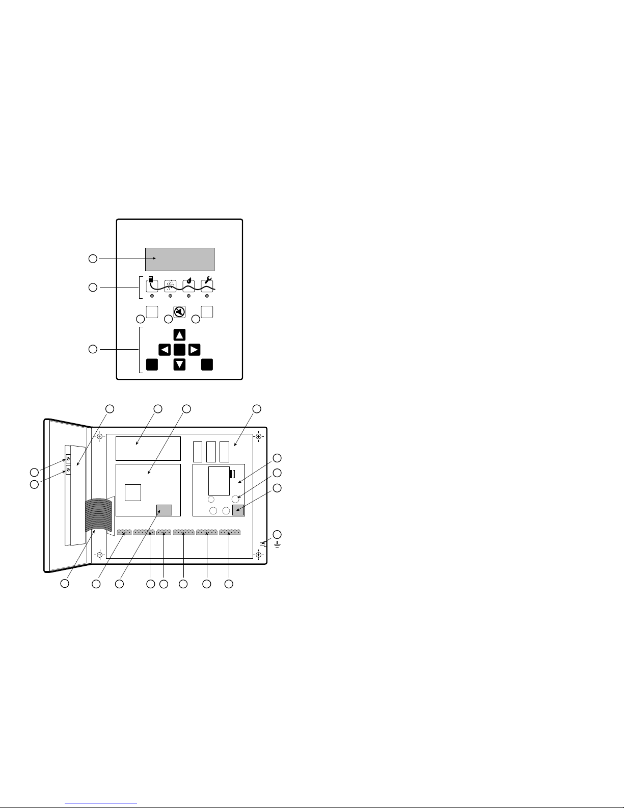
Identifying TTDM Features
External View [A]
(1) LCD display gives up-to-date
information regarding the condition of
the system.
(2) Icons and LEDs (light emitting
diodes):
Monitoring LED green
Service (Required) LED yellow
Leak LED red
Fault LED red
(3) (Self) Test key
Can be used at any time to
verify the correct operation of the
module. The module performs a
series of self-diagnostic checks.
(4) Silence key
Used to silence audible alarms
(5) Reset key
Used to reset the leak alarm relay
after a leak has been cleared.
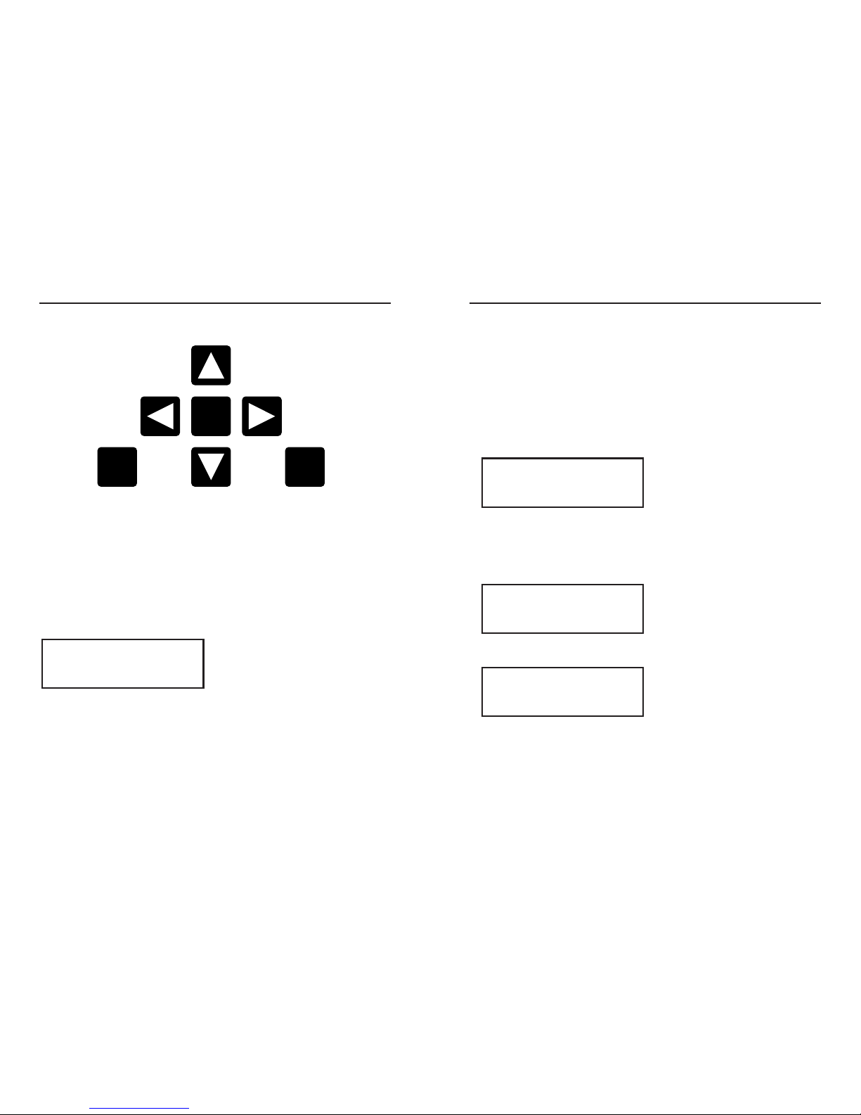
(6) Menu keys
The menu button provides access to
various features that may be viewed
and/or edited. The menus are navigated
with the arrow keys together with the
Esc (escape) and Enter keys.
Internal View [B]
(7) User interface board
(8) 4–20 mA board
(9) Sensor interface board
(10) Motherboard
(11) Power supply board
(12) Fuse (200 mA, 250 V)
(13) Power cable terminal block
(14) Ground (earth) stud
(15) Fault relay cable plug and socket
(16) Leak relay cable plug and socket
(17) Service relay cable plug and socket
(18) 4–20 mA port plug and socket
(19) RS-232/485 port plug and socket
(20) Sensing cable plug and socket
(21) Reserved for future use
(22) Ribbon cable
(23) Volume adjustment
(24) LCD contrast adjustment
ii
ResetTest
EnterEsc
Menu
RTraceTek
TTDM
1
2
6
34 5
7
23
24
98 10
11
13
12
14
151617
18
1920
22 21
A
B
i

Contents
1
Identifying TTDM Features . . . . . . . . . . . . . . . . . . . . . . . . . . . . . . . . . . . . . . . . . . . . . . .ii
Introduction . . . . . . . . . . . . . . . . . . . . . . . . . . . . . . . . . . . . . . . . . . . . . . . . . . . . . . . . .iii
Leak Detection System Description . . . . . . . . . . . . . . . . . . . . . . . . . . . . . . . . . . . . . . . .2
Connection to Other Devices . . . . . . . . . . . . . . . . . . . . . . . . . . . . . . . . . . . . . . . . . . . . .4
The Basic Events . . . . . . . . . . . . . . . . . . . . . . . . . . . . . . . . . . . . . . . . . . . . . . . . . . . . . .6
Leak Detection and Location Events . . . . . . . . . . . . . . . . . . . . . . . . . . . . . . . . . . . . . . . .8
Service Events . . . . . . . . . . . . . . . . . . . . . . . . . . . . . . . . . . . . . . . . . . . . . . . . . . . . . . .10
Fault Events . . . . . . . . . . . . . . . . . . . . . . . . . . . . . . . . . . . . . . . . . . . . . . . . . . . . . . . .12
Multiple Events . . . . . . . . . . . . . . . . . . . . . . . . . . . . . . . . . . . . . . . . . . . . . . . . . . . . . .14
Navigating the Menu Structure . . . . . . . . . . . . . . . . . . . . . . . . . . . . . . . . . . . . . . . . . .18
The Events History Log . . . . . . . . . . . . . . . . . . . . . . . . . . . . . . . . . . . . . . . . . . . . . . . .19
Diagnostics (System Status) . . . . . . . . . . . . . . . . . . . . . . . . . . . . . . . . . . . . . . . . . . . .20
Changing Settings (View/Edit Settings) . . . . . . . . . . . . . . . . . . . . . . . . . . . . . . . . . . . .22
Appendix 1 - Menu Structure . . . . . . . . . . . . . . . . . . . . . . . . . . . . . . . . . . . . . . . . . . . .25
Appendix 2 - Events Glossary . . . . . . . . . . . . . . . . . . . . . . . . . . . . . . . . . . . . . . . . . . .26
Appendix 3 - Maintenance . . . . . . . . . . . . . . . . . . . . . . . . . . . . . . . . . . . . . . . . . . . . . .28
Appendix 4 - Interface Details . . . . . . . . . . . . . . . . . . . . . . . . . . . . . . . . . . . . . . . . . . .30
Appendix 5 - Wiring Details . . . . . . . . . . . . . . . . . . . . . . . . . . . . . . . . . . . . . . . . . . . . .32
Appendix 6 - TraceTek Technical Data . . . . . . . . . . . . . . . . . . . . . . . . . . . . . . . . . . . . . .33
Please read before use
Please read these instructions carefully and keep in a safe place (preferably close to the
module) for future reference.
The instructions provided in this booklet must be followed carefully to ensure proper
operation. If the equipment is used in a manner not specified by the manufacturer, the
protection provided by the equipment may be impaired.
Description
The TTDM module has been specifically designed for use with TraceTek sensing cables
(all TT1000, TT3000, and TT5000 series sensing cables, and all TT100, TT300, and TT500
series long-line sensing cables). TTDM can monitor up to 5000 ft (1500 m) of sensing
cable and can detect and locate the presence of liquid at any point along the cable. The
module also monitors the system for other alarm conditions:
• Service required
•Fault
Each “event” (service, leak, or fault) is recorded in an Events History with the time and
date of occurrence. This allows easy tracking of events.
Preparation
Before operation, the instructions in the “TTDM Installation Instructions” that accompany
the system must be followed so that the module is properly:
• Mounted
• Powered (wired and energized)
• Connected to a TraceTek sensing cable with a TraceTek jumper or leader cable
• Commissioned (a completed commissioning form should be supplied)
If these steps have not been taken, please refer to the “TTDM Installation Instructions” in
order to complete the installation.
In addition, there should be a system map, which indicates the sensing cable layout with
reference landmarks throughout the system.
Notes
• Throughout this manual, the examples shown use distances in feet.
• Later versions of software may provide new features and change certain other details.
This manual documents UI Version 1.05.
Introduction
iii
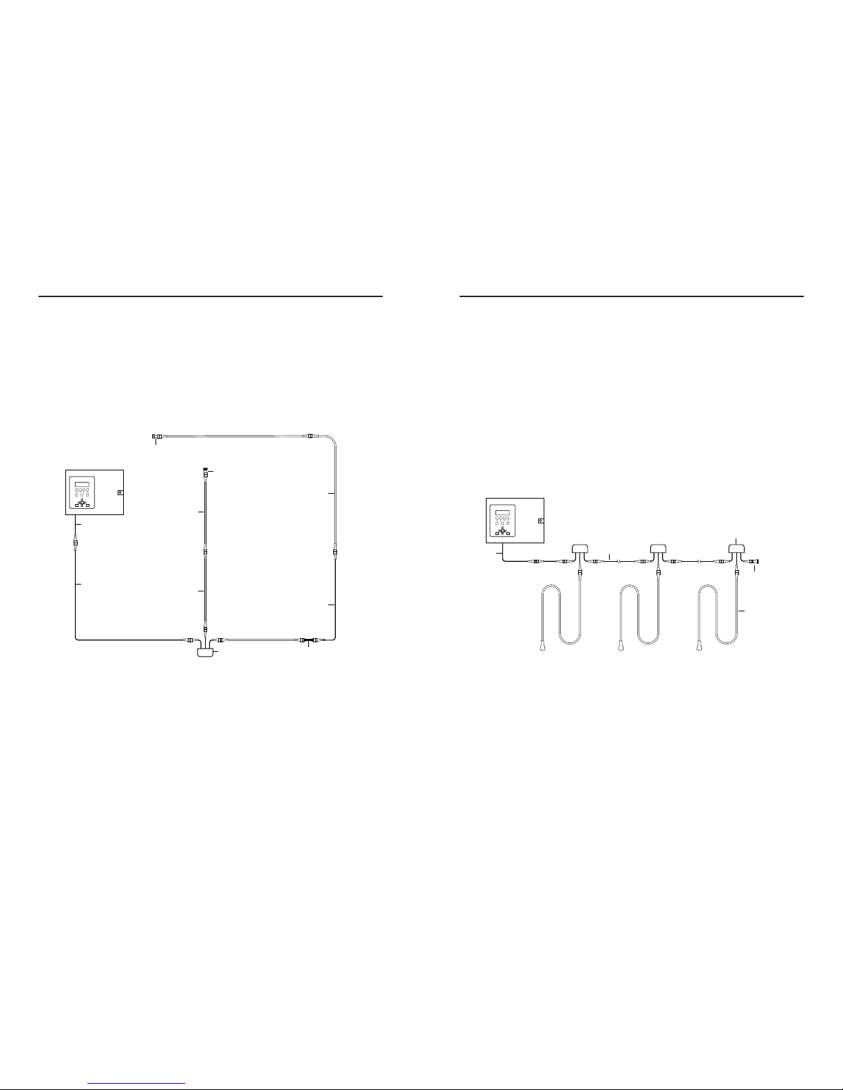
The TraceTek Zone System
The TraceTek zone system is a leak detection and location system that monitors many
separate locations from one point. The zone system consists of the TTDM Alarm and
Locating Module and up to 100 separate sensing zones interconnected by one run of
jumper cable.
Each sensing zone consists of a zone connector and one 5 ft (1.5 m) length of sensing
cable. If liquid is detected, the module signals the alarm and displays the zone where the
leak has occurred. The zones are numbered sequentially by the system electronics.
Important: In a TraceTek zone system, only
zone
sensing cables (TT3000 zone or
TT5000-series zone) may be used. Each sensing cable plugs into a zone connector.
The last zone connector must have an end termination.
ModeResetTest
Test
POWER
ON ZONE1
ON ZONE2
ON ALARM
EnterEsc
Menu
RPROTRAC2
/ / / / / / / / / / / / / / / / / / / / / / / / / / / / / / / / / / / / / / / / / / / /
/
/
/
/
/
/
/
/
/
/
/
/
/
/
/
/
/
/
/
/
/
/
/
/
/
/
/ / / / / / / / / / / / / / / / / / / / / / / / / / / / / / / /
/
/
/
/
/
/
/
/
/
/
/
/
/
/
/
/
/
/
/
/
/
/
/
/ / / / / / / / / / / / / / / / / / / / / / / / / / / / / / / / / / / / / / / /
TTDM
Alarm and
Locating Module
Zone
sensing
cable
Jumper
cable
End
termination
Zone
connector
Modular
leader
cable
TraceTek Longline System
A TraceTek longline system provides distributed leak detection and location to monitor
long lengths and wide areas. The system consists of the TTDM Alarm and Locating
Module and up to 5000 ft (1500 m) of sensing cable.
The sensing cable detects liquid at any point along its length. The module then signals the
alarm and displays the distance to the leak.
The longline system includes sensing cable and circuit components (leader cable, jumper
cables, end terminations, weighted lengths, and branching connectors) with connectors
that allow components of the system to plug together.
The weighted length resistor simulates a 15 ft (5 m) length of sensing cable. Installed at
the boundary between two areas, it allows the user to clearly identify the area where the
leak has occurred.
The branching connector enables the sensing cable to be branched. An end termination
completes each branch. At the branching connector, the system first counts the sensing
cable along the branch (middle connector), before it continues with the main run. Two
built-in 15 ft (5 m) weighted length resistors allow the user to clearly identify on which
leg a leak has occurred near the branching connector.
An important part of the TraceTek longline system is the system map, a sensing cable
layout plan with actual distance readings. Thus, in case of an alarm, the location of the event
can be determined quickly. The map should be placed near the Alarm and Locating Module.
/ / / / / / / / / / / / / / / / / / / / / / / / / / / / / / / / / / / / / / / / / / / / / / / / / / / / / / / / / / / / / / / / / / / / / / / / / / / / / / / / /
/
/
/
/
/
/
/
/
/
/
/
/
/
/
/ / / / / / / / / / / / / / / / / / / / / / / / / / / / / / / / / / / / / / / / / / / / / / / / / / / / / / / / / / / / / / / / / / / / / / / / / / / / / / / / / / / / / / / / / / / / / / / / / / / / / / / / / / / / / / / / / / / / / / / / / / / / / / / / / / / / / / / / / / / / // / / / / // / /
/
/
/
/
/
/
/
/
/
/
/
/
/
/
/ / / / / / / / / / / / / / / / / / / / / / / / / / / / / / / / / / / / / / / / / / / / / / / / / / / / / / / / / / / / / / / / / / / / / / / / / / / / / / / / / / / / / / / / / / / / / / / / / / / / / / / / / / / / / / / / / / / / / / / / / / / // / / / / /
ModeResetTest
Test
POWER
ON ZONE1
ON ZONE2
ON ALARM
EnterEsc
Menu
RPROTRAC2
/ / / / / / / / / / / / / / / / / / / / / / / / / / / / / / / / / / / / / / / / / / / / / / / / / / / / / / / / / / / / / / / / / / / / / / / / / / / / / / / / / / / / / / / / / / / / / / / / / / / / / / / / / / / / // / / / /
TTDM
Alarm and
Locating Module
Modular
leader cable
Jumper
cable
Modular
branching
connector
Weighted
length
Jumper
cable
Sensing
cable
End
termination Modular end
termination
Sensing
cable
Sensing
cable
2 3
Leak Detection System Description

Serial Port
The TTDM module has a serial port (marked EXT COM PORT) that can be configured for
use either as an RS-232 or RS-485 transceiver. The factory default is RS-232, and is
suitable for connecting the TTDM to single devices up to 50 ft (15 m) away. The standard
configuration is RS-232 full-duplex with no hardware handshaking, which is suitable for
connection to many devices (such as a remote host PC, laptop, or modem).
The RS-232/485 port (19 on foldout) is connector J13 on the TTDM motherboard. The
pinouts for connector J13 on the TTDM motherboard are listed below, with functions for
RS-232 usage noted.
Pin Desc. Use
J13-5 RX/A Receive data
J13-6 TX/B Transmit data
J13-7 RTS Request to send —
for hardware handshaking
J13-8 CTS Clear to send —
for hardware handshaking
J13-9 +5V/DTR +5V supply/DTR if
needed by modem
J13-10 GND Supply return
Note: For further information, see Appendix 4 - Interface Details.
Relays
TTDM has three relays:
• Service
• Leak
• Fault
Each relay provides two Form-C relay contacts, with normally open and normally closed
contacts both provided. The relays are
de-energized to indicate an alarm
condition. The
diagram below shows the relay status when each is in an alarm (de-energized) state.
(For other connection options, please consult Appendix 5 - Wiring Details.)
4–20 mA
The module is equipped with an analog 4–20 mA interface. The TTDM adjusts its current
output based on whether an alarm condition exists, and (when a leak is detected) the
location of the leak. Its output can be scaled to make full use of the 4–20 mA range for
the length of sensing cable connected.
Note: The current transmitter is isolated from the sensing circuitry and therefore requires
an external 24 Vdc power supply.
The 4–20 mA output port (18 on foldout) is connector J2 on the TTDM motherboard,
with terminals as noted in the following table:
Pin Desc. Use
J2-11 IRTN Current loop return
J2-12 IOUT Current output
J2-13 +V 24 Vdc supply (required)
J2-14 +VRTN 24 Vdc common (required)
Note: More information about operation and testing is found in Appendix 4 -
Interface Details.
15 16 17 201918 21 22 23 262524 27 28 29 323130
LEAK RELAYSERVICE RELAY FAULT RELAY
4 5
Connection to Other Devices

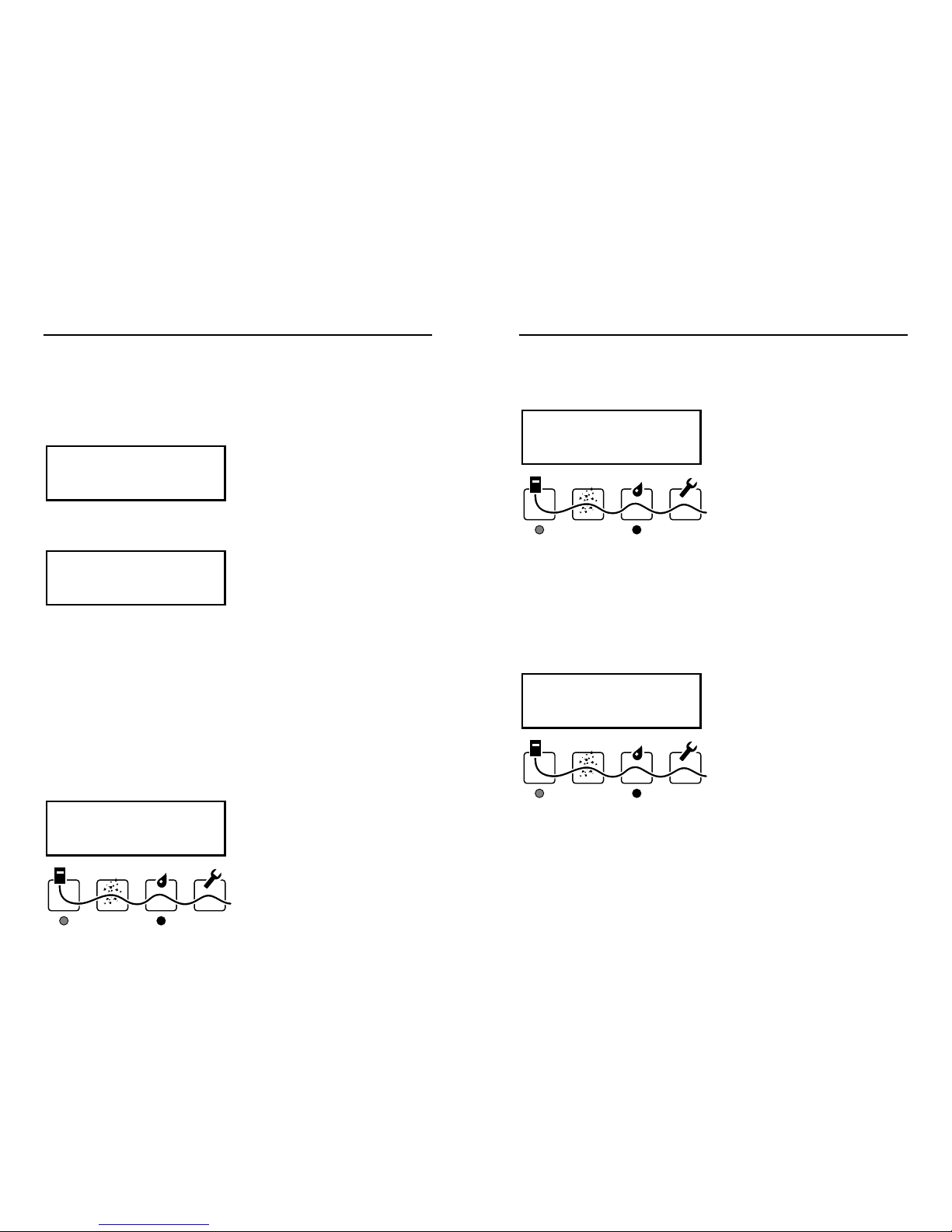
Leak
When liquid is detected on the sensing cable, this red Leak LED illuminates. Note that the
green LED remains illuminated; the unit continues to monitor for leaks and spills. This is cov-
ered more fully in the following section “Leak Detection and Location Events”, on page 8.
Fault
When the TTDM module detects a fault—either a cable fault, or an electronics fault—it
lights this red LED. Note that in a Fault condition, the TTDM module is unable to detect a
leak. For further information, see the “Fault Events” section on page 12.
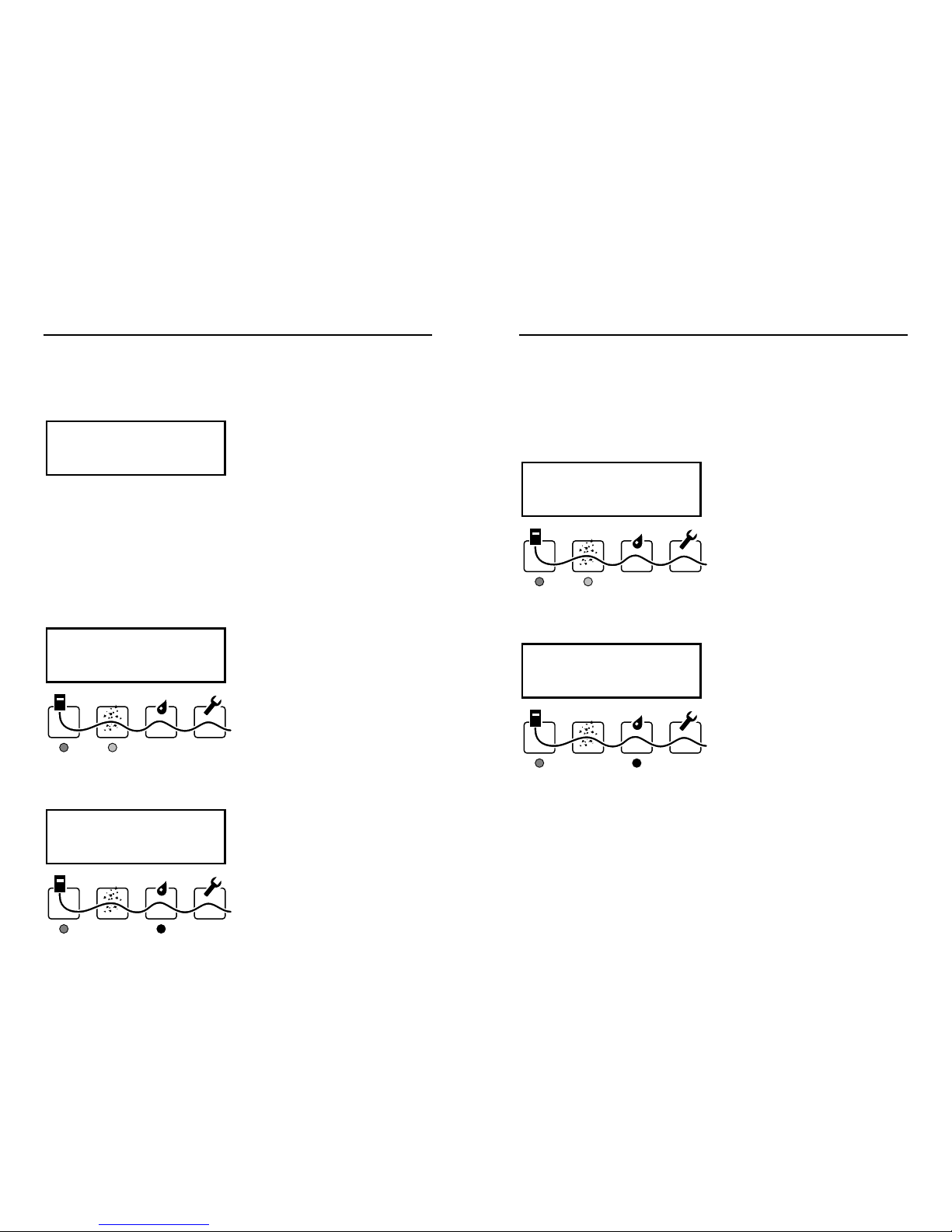
LCD Display
Line 1 indicates the original location of a leak.
Line 2 indicates the present status (except when a leak is initially detected, since the ini-
tial location is always shown on line 1).
Line 3 may advise action or provide special instructions.
Line 4 displays the current time and date (the colon blinks once a second). To highlight
the present status, the line of the display with the most recent event flashes.
Hint: The LCD contrast may be adjusted (24 on foldout).
Leak 10 ft
Leak Cleared
Press Reset
16:30 14-Feb-1996
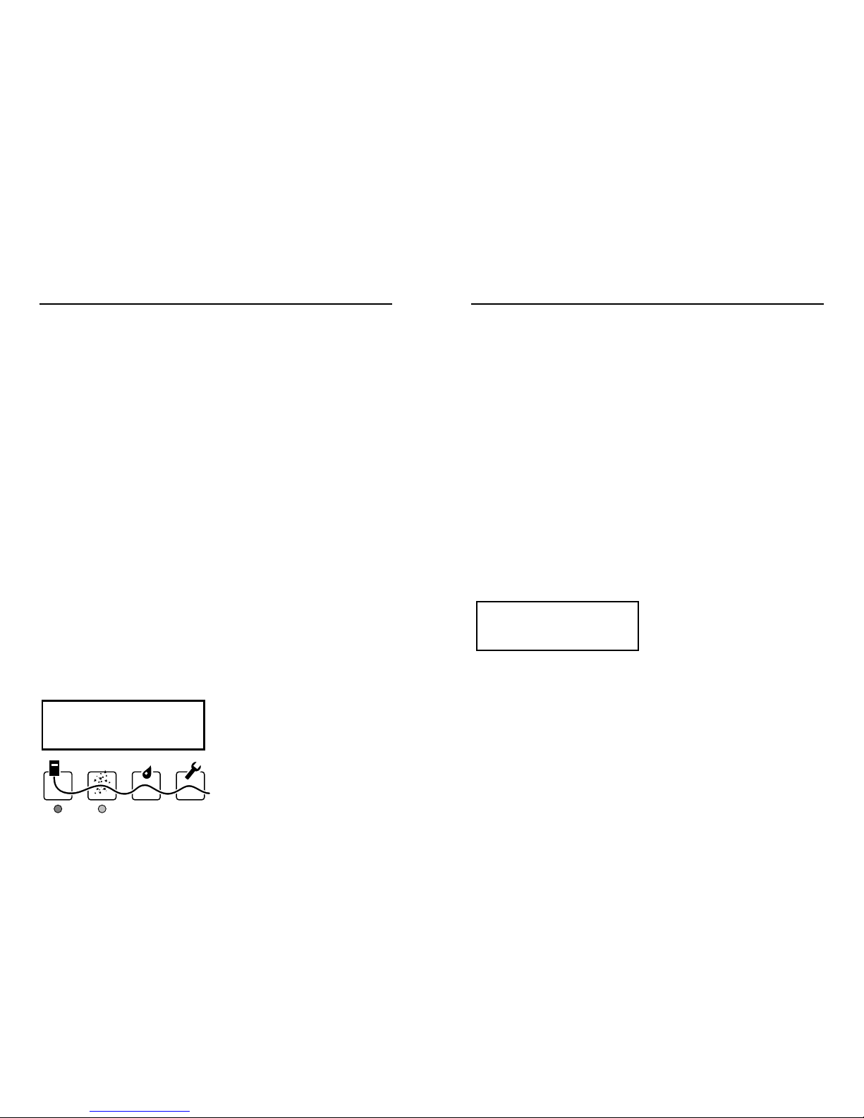
The Icons
The Icons (2 on foldout) represent the four main states of the TTDM module:
Monitoring
This green LED indicates that the TTDM is monitoring the sensing cable. If something
happens that makes it impossible for the TTDM to monitor the sensing cable (for exam-
ple, the cable is broken), the Monitoring LED will extinguish.
Service
The TTDM is able to give advance warning of potential problems. This yellow Service LED
illuminates to indicate that service is required. Note that the green LED remains illuminated;
the unit continues to monitor for leaks during a Service alarm.
See the “Service Events” section on page 10 for further details.
Monitoring
Service
Leak
Fault
Green Yellow Red Red
6 7
The Basic Events

To Locate the Leak
Using the number displayed by the TTDM, refer to the system map and determine where
the leak was detected.
To Clear the System
Fix the leak and cleanup the area affected. Then dry the sensing cable (in the case of
TT1000 and TT3000) or replace the tripped section (TT5000 family).
Once the sensing cable is clear, the module responds and the display changes:
Notice that the red LED remains on. This is to indicate that the leak relay is still in the alarm state.
To Reset the Leak Relay
In order to reset the leak relay and return the module to the “System Normal” state, press
the reset button. Before doing so, check that any external or remote equipment controlled
by the TTDM is ready to be reset.
Hint: If manual reset is not required, the module can be set to auto-reset
(see “Auto-Reset” under “Leak Settings” on page 23).
Once the Reset button is pressed, the relay returns to normal, the red Leak LED
extinguishes, and the LCD display changes:
System Normal
16:53 14-Feb-1996
Leak 10 ft
Leak Cleared
Press Reset
16:30 14-Feb-1996
If the TTDM unit has been installed correctly, and the system is clear, the LCD display will
appear as follows:
Leak
When liquid is detected, the following occur:
• The audible alarm sounds.
• The red Leak LED illuminates.
• The interfaces (relays, 4–20 mA, serial port) respond.
• The display changes to show the location of the leak:
The following actions should be taken:
• Silence the alarm.
• Locate the leak.
• Clear the system.
• Reset the leak relay.
To Silence the Alarm
Press the Silence key to silence the audible alarm.
Hint: If audible alarms are not required, the module can be set to disable them (see
“Audible Alarm” under “Leak Settings” on page 23).
Leak 10 ft
16:00 14-Feb-1996
System Normal
15:53 14-Feb-1996
8 9
Leak Detection and Location Events
The number in square brackets indicates the estimated location of the material causing
the alarm. The number is shown with square brackets to indicate that the value is only an
estimate.
Hint: Because the cause (concrete dust for example) of low-level current may be distrib-
uted over several feet/meters of cable, it is not always possible for the TTDM to return an
accurate location. However, the indicated location is always a good point from which to
begin a troubleshooting procedure.
The following actions should be taken:
• Silence the audible alarm.
• Clear the cable.
To Silence the Audible Alarm
Press the Silence key to silence the alarm.
To Clear the Cable
Investigate the cause of the alarm and conduct cleanup or maintenance accordingly.
Hint: If material causing a service alarm is spread throughout the system, it is often
useful to subdivide the system; see Appendix 3 - Maintenance, for further information.
When the material (such as moisture or concrete dust) or conditions causing the alarm
are removed, the yellow LED goes out, and the service relay returns to its normal state:
System Normal
16:57 14-Feb-1996
Introduction
A TraceTek sensing circuit consists of two electrical loops (a diagram of the sensing
circuit is shown in Appendix 6). The TTDM module constantly monitors to see whether
current is passing between the loops. When the system is normal, there is no current
passing between the loops. When there is a leak on the system, the maximum current
flows (just 270 µA; the sensing cable operates on low voltage and is safe to touch).
If, however, the TTDM module detects a lower but significant level of current flow
between the loops, it activates the Service alarm.
A low-level current could indicate one or more of the following:
•A very small leak (which may soon develop into a full leak alarm).
• Heavy condensation or small spills (coffee, tea, etc.) on a water-sensing or aqueous-
chemical-sensing cable (TT1000 and TT3000).
•Conductive material on a water-sensing or aqueous-chemical-sensing cable. The
material might be metal filings, concrete dust, flux, mastic, or other construction
debris, or carbon-based dust from air-handling units, printers, or copiers.
While it is recommended that service alarms be investigated, the operation of the system
is not threatened; the TTDM will continue to detect leaks. However, the accuracy of loca-
tion may be affected in certain cases.
The Service Alarm
When a condition requiring service (such as described above) is detected, the following
occur:
• An intermittent beep sounds.
• The yellow Service LED illuminates.
• The service relay goes to alarm condition.
•The LCD display changes to the following:
Service ReqÕd [11]
15:53 14-Feb-1996
10 11
Service Events

To Remedy the Problem
Find the problem and rectify. This may mean reconnecting the cable, or finding the dam-
aged section and replacing it. If the cause of the fault is not obvious by visual inspection,
it is often useful to subdivide the system and test individual sections with a TraceTek
Portable Test Box.
As soon as the fault is rectified, the relay, LED, and LCD screen return to their
normal state:
System Normal
15:53 14-Feb-1996
Introduction
Several conditions could lead to a fault alarm:
• A cable is disconnected.
• A cable is damaged.
• A connection is damaged.
• There is a problem with the module.
What the Module Does
The following shows how the alarm display would appear if the fault were caused by a
broken or disconnected cable. (The TTDM would display a different message for a differ-
ent type of fault, such as a loss of continuity in only one of the sensing loops):
When a fault condition is detected, the following occur:
• An audible alarm sounds.
•The green Monitoring LED turns off (no longer able to detect a leak).
• The red Fault LED turns on.
• Interfaces react.
The following actions should be taken:
• Silence the audible alarm.
• Remedy the problem.
To Silence the Audible Alarm
Press the red Silence key to silence the alarm.
Cable Break
17:53 14-Feb-1996
12 13
Fault Events
Example (continued):
Before the problem can be dealt with, the leak spreads. Once the module has detected
significant movement (that is, greater than the Re-Alarm distance—see “Re-alarm dis-
tance” on page 23 for more detail), the module goes into alarm once again:
The LCD now displays the FIRST leak and the MOST RECENT alarm. The FIRST recorded
leak is likely to be close to the source of the leak.
The MOST RECENT leak shows the current “electrical center” of the liquid (essentially a
weighted average). If the re-alarm number is close to the first (as in the example above),
it is likely that the leak has spread.
Should the leak continue to spread, the TTDM would re-alarm again; the second line is
updated again:
Hint: Use the Events History to track the events between the “first leak” and the “most
recent event.” See “The Events History Log” section on page 19.
Leak 50 ft
Re-Alarm 60 ft
16:23 14-Feb-1996
Leak 50 ft
Re-Alarm 55 ft
16:01 14-Feb-1996
In addition to storing all events in memory, TTDM gives a direct indication of multiple
events, that is, events which happen after an initial leak but before the module is manually
reset.
The first line of the display always indicates where the liquid was first detected.
This location is the most useful in identifying the source of the leak.
The second line displays the most recent event. For example:
The second line flashes to highlight the present status. If the cable is then disconnected,
the display will change again:
Notice that the first line remains unchanged. The second line changes to reflect the
present condition of the system.
Moving Leak
The TTDM continues to monitor during “service” and “leak” alarms, ensuring that the
installation is afforded full-time protection.
The TTDM will re-alarm when the leak moves more than the re-alarm distance, for which
the default is 5 ft (1.5 m). The audible alarm will sound, the second line of the LCD will
change, and a new event will be added to the Events History.
Example:
Suppose a leak is detected at 50 feet:
Leak 50 ft
15:59 14-Feb-1996
Leak 11 ft
Cable break
15:53 14-Feb-1996
Leak 11 ft
Re-Alarm 20 ft
15:53 14-Feb-1996
14 15
Multiple Events
Note how this leak event differs from the simpler leak event detailed on page 8:
• Rather than displaying the message “Leak 50 ft,” the display puts the location in square
brackets. This indicates that 50 ft is the likely location of the leak.
Case 2 - Service, then leak at same location
If a leak is detected at nearly the same location as that causing a Service Required alarm,
TTDM operates differently, as shown below.
First, there is an alarm for Service Required.
Subsequently, a full-fledged leak is detected at nearly the same location. The TTDM
responds as shown below:
Since the Service Required alarm was at the same location, it is interpreted as an early
indication of the leak. The TTDM therefore clears the service alarm, and displays the leak
location without brackets.
Leak 239 ft
17:45 28-Feb-1996
Service ReqÕd[237]
16:53 28-Feb-1996
16 17
Additional Leak
If liquid contacts the sensing cable away from the initial leak, the module will re-alarm. If
the location is distant from the last alarm, the TTDM shows a location in square brackets.
Brackets indicate that the value shown requires interpretation; when an additional leak
occurs, the value represents the “electrical center” of the leaks.
The display also prompts the user to check the Events History log in order to investigate
the sequence of events between the first leak at 50 ft, and this re-alarm event.
Service-to-Leak Alarm
Case 1 - Different locations
Although TTDM can continue to monitor when a Service Required alarm is in effect, the
accuracy of location may be impaired. TTDM indicates this by displaying the leak location
in square brackets.
Example:
If a leak contacts the sensing cable before service was performed, the display would
appear as below:
Leak [50]
15:53 14 Feb 1996
Service ReqÕd[2003]
15:53 14-Feb-1996
Leak 50 ft
Re-Alarm [1045]
15:53 14-Feb-1996
One extremely useful function provided by TTDM is the ability to record a series of
events. The TTDM module keeps track of a list of 512 events.
For a full list of event types, please refer to “Appendix 2 - Events Glossary” on page 26.
Accessing the Events History Log
• Press Menu.
•Select Events History (scroll down with the down arrow key).
• Press Enter.
The most recent (that is, current) event is displayed:
The arrow at the bottom right-hand corner indicates that there are further events
‘below’ (= before) this one. The bottom line of the display indicates that the unit has
recorded 23 events, and the one displayed is the most recent event.
• Press Down Arrow key. The previous event is displayed:
• Press Down Arrow key again. The third from last event is displayed:
Hint: To quickly move to a view of the most recent event, press the Right-Arrow key.
To move to the oldest event, press the Left-Arrow key.
The TTDM can store up to 512 events. If 512 events are already stored, the oldest event is
discarded as a new event is registered. When this has occurred, the Events History leaves
the bottom line of the display blank. Contact Raychem for assistance if you wish to clear
the event history.
Events History:
▲
Leak 250 ft
■
09:01 13-Feb-95
■
[21 of 23]
▼
Events History:
▲
Leak Cleared
■
11:33 15-Feb-95
■
[22 of 23]
▼
Events History:
■
* Reset
■
09:01 17-Feb-95
■
[23 of 23]
▼
Please refer to “Appendix 1 - Menu Structure” on page 25 for an overview of the menu
structure and to item 6 on the foldout for the menu keys which are also shown below:
Start by pressing the Menu key.
Use the four arrow keys to scroll through menu items, and to select individual characters.
To go one level deeper into the menu structure, press Enter.
To go back one level in the menu structure, Press Esc.
The Scroll Bar
The scroll bar (see example below) indicates that there is more information off screen; the
arrow indicates the direction of further information:
View/Edit Settings
■
General
■
Leak
■
Ports
▼
EnterEsc
Menu
18 19
The Events History LogNavigating the Menu Structure

Location
The current location—or electrical center—of the leak (or cause of a Service alarm). If the
status is System Normal, the Location entry is blank.
Current
This current (measured in µA) indicates the condition of the sensing cable. If a leak is detected,
this rises to 270 µA. In a clean, leak-free system, the current should be 5 µA or less. If the cur-
rent rises above 20 µA, service is recommended, as it may indicate the presence of contamina-
tion. To better understand what this current means, see “Appendix 6 - TraceTek Technical Data”,
which explains the TraceTek operating principle.
R S-to-S
This is the resistance from sensing wire to sensing wire (see Appendix 6 for detail). For a
clean, leak-free system, this resistance is in the M½range. If liquid is detected, it drops to
the k½range or even lower. If the value is changing, it may indicate an event in progress.
R RG Loop, R YB Loop
These are the resistances of the Red-Green and Yellow-Black loops in the TraceTek sens-
ing circuit (see Appendix 6 for detail). If these values are significantly different from each
other, it may indicate damage to a sensing cable or connector.
SI Version, UI Version
These indicate the versions of the sensor interface and user interface software that are
operating.
The next line in the display was left blank intentionally because the entries that follow are
unlikely to be used except for reference in troubleshooting.
R Loc
This is the resistance measured along the black sensing wire to the location of the leak
(see Appendix 6 for detail).
SI Status, UI Status
These hexadecimal values indicate the current status of the Sensor Interface and User
Interface, respectively, and may assist factory personnel providing diagnostic support.
SI Comm
This indicates the success rate (in percent) for communications between the Sensor
Interface and User Interface boards. A value below 90% may indicate a faulty connection
or damaged ribbon cable.
System Status
System Status provides a real-time view of the system. You gain access to this feature
through the main menu. When System Status is selected, the TTDM displays the follow-
ing screen (the “{system status}” entry on the second line is explained below):
The arrow at the bottom right indicates other entries can be accessed with the down
arrow key. The complete list of information available in System Status is shown below:
“{system status}”
This is a variable field, which can contain any of the following text, depending on the state
of the system:
• System normal
• Leak
• Re-alarm
• Service Required
•Fault (specific entries are shown in Appendix 2)
Test Length
The Test Length should be the same as that recorded when the system was mapped. If it
is not, it may mean that the system was modified (sensing cable was removed or added).
Note: The Test Length is typically about 1% longer than the physical or mapped length of
the system. This is normal.
System Status
{system status}
Test Length 4785 ft
Location ----- ft
Current 0 µA
R S-to-S ----- k½
R RG Loop 18658 ½
R YB Loop 18656 ½
SI Version 100
UI Version 105
R Loc 0 ½
SI Status 1024
UI Status 1024
SI Comm 100
System Status:
■
{system status}
■
Test Length 4785 ft
■
Location ----- ft
▼
Diagnostics (System Status)
20 21

Language
Select from available options (English, Français,...)
Change Password
Enter the new password (using the arrow keys) and press Enter.
Don’t forget your password! Write it down in a safe place!
Hint: If password protection is not required, set the password to 0000. After that, you
will not be prompted for a password.
Leak Settings
You gain access to the Leak settings through the View/Edit Settings Menu, which is on
the main menu (see page 25 for the menu structure).
Re-alarm distance
This is the distance over which the electrical center of the leak must move before TTDM will
re-alarm. It can be set between 3 ft (1 m) and 20 ft (6 m); the factory default is 5 ft (2 m).
Re-alarm interval
The TTDM can be made to re-alarm automatically if a leak has not been cleared after a certain
length of time. Choose from:
•Never (factory default)
• 8 hr
• 12 hr
• 24 hr
Hint: Use this to automatically alert the next shift when the system has an uncleared leak.
Auto-reset
By default, TTDM requires a manual reset following a leak event. This allows the user to,
for example, verify that any equipment controlled with the Leak relay is ready to be
switched back on.
TTDM can be set to “auto-reset” following a leak. In this case, the leak relay will revert to
the normal state as soon as the leak has been cleared.
• Select: Auto-reset – On
Audible alarm
The audible alarm may be disabled if not required.
• Select: Audible Alarm – Off
Hint: The volume may be adjusted (23 on foldout).
You gain access to the system’s settings through the View/Edit Settings Menu, which is
on the main menu (see “Appendix 1 - “Menu Structure” on page 25). Four types of set-
tings are available:
• General
• Leak
• Ports
• Self-Test
In certain parts of the menu structure, settings may be changed only after entering a password.
Entering a Password
When an attempt is made to change a restricted setting, a password prompt will appear.
Proceed as follows:
•Use left/right arrow keys to move to each digit.
• Use the up/down arrows to increase/decrease the number.
• Press Enter when complete.
The module is supplied from the factory with the password 0010. However, the password
may be changed if required (see the explanation under “General Settings” below).
Note: Once the password is entered, it remains in effect (allowing access) until exit from the main
menu to the normal monitoring screen, or until there has been no keypad activity for 30 minutes.
Changing a Setting
When the value or selection for a setting has been changed, either:
• Press the Enter button to accept the change.
• Press the Esc button to cancel the change.
General Settings
You gain access to the General settings through the View/Edit Settings Menu, which is on
the main menu (see page 25 for the menu structure).
Date/Time
Use left/right arrow keys to select each digit. Use the up/down arrow keys to
increase/decrease the number.
Units
Use the cursor to select feet, meters, or zones as required. Note: Do not choose zones
unless the system includes only zone sensing cables with zone connectors.
Password:
0000
^
0000...4095
Changing Settings (View/Edit Settings)
22 23
2524
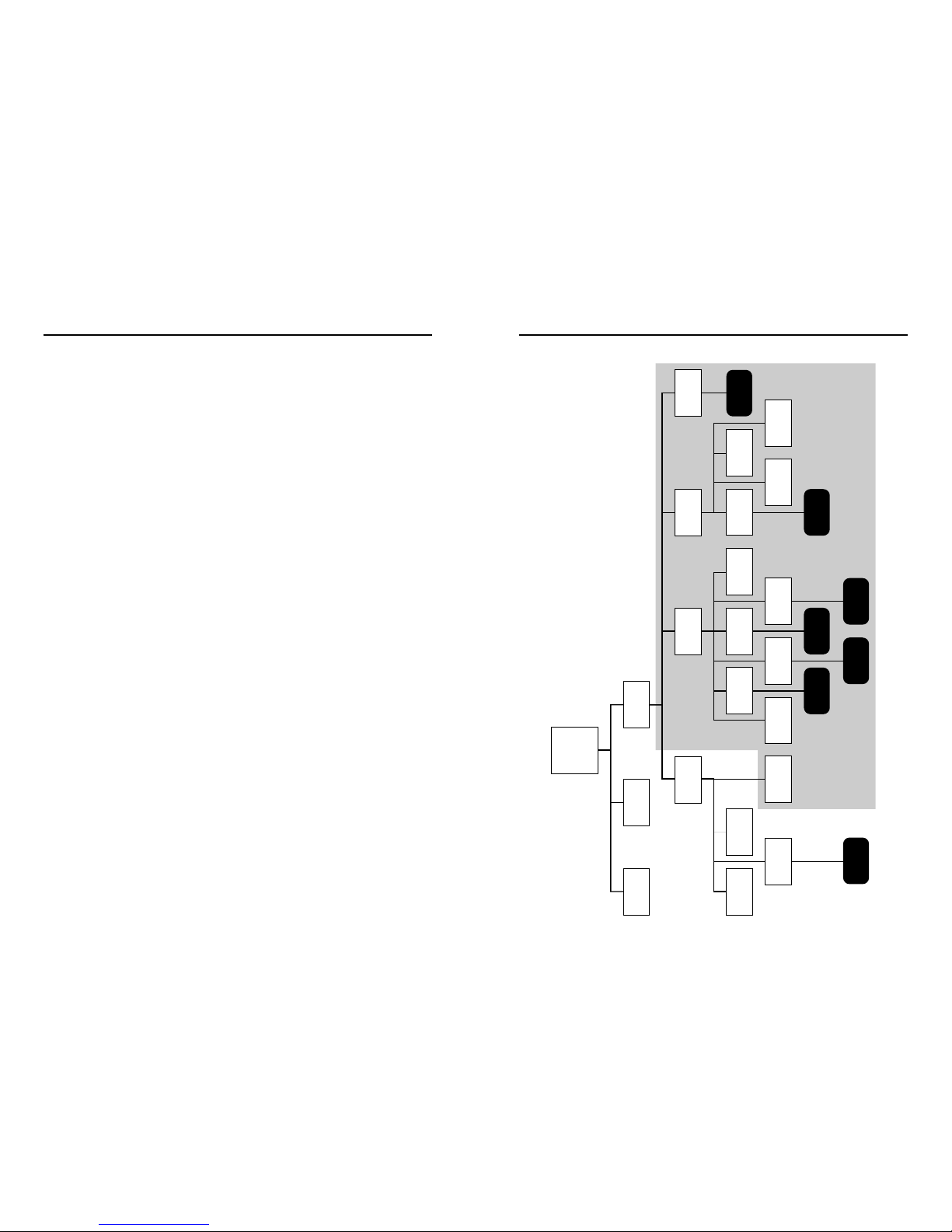
Appendix 1 - Menu Structure
Sensitivity
Select:
• “normal” sensitivity for most applications
• “high” sensitivity for de-ionized water
• “low” sensitivity for particularly active or exposed applications
Barrier Resistance
If you are using a zener barrier (or a lightning protection device) its resistance can be
“dialed out” so the system map can begin at 0.
Note: Always set this value BEFORE mapping the system. Consult your Raychem TraceTek
representative for further details.
Port Settings
You gain access to the Port settings through the View/Edit Settings Menu, which is on the
main menu (see page 25 for the menu structure).
Baud
The serial port can be set to a variety of communications rates. The default is 9600.
Modem
This selects a menu of modem commands. Contact Raychem for additional information.
485 Address
This entry assigns an RS-485 address for the TTDM. This will allow multiple TTDM units
to be networked. Contact Raychem for additional information.
Terminal
This selection provides a real-time display of communications to and from a modem or
host system, which can be helpful for diagnostic purposes.
Self-Test Settings
You gain access to the Self-Test settings through the Self-Test Menu, the last item on the
View/Edit Settings Menu, (see page 25 for the menu structure).
The Self-Test Menu allows individual functions to be tested, and expands on tests per-
formed when the (self) Test key is pressed. The tests available for a function are displayed
after that function is selected from the Self-Test Menu. They include:
• UI test (User Interface) • Keypad
• Memory Tests • Relay Test
• SI test (Sensor Interface) • 4–20 mA Test
• Audio Test • Ext Comm Loop Back Test
• Display Test (for serial port)
General
Time/Date Language
Units Password
Leak Ports Self-Test
Menu
feet
metres
zones
Low
Normal
High
ReAlarmInt AudibleAlarm Barrier Res
Auto ResetReAlrmDist Sensitivity
Select...
485 Address
Modem Terminal
On
Off
Select...
Baud
Select...
On
Off Password required to change settings
Menu
View/Edit
Settings
System
Status
Events
History

SI H/W Error A self-test of the Sensor Interface Hardware has
failed; the unit needs repair.
✓SI H/W Recovered The hardware problem has been corrected.
Service Service Req’d A small amount of current is flowing between
the two sensing wires; this usually indicates
something is contacting the sensing cable that
should be investigated and corrected.
✓Service Clear The condition requiring service has been cleared.
User action {Settings} Changed When a user changes settings, the name of the
setting, the time, and date are recorded in the
Events History log.
Alarm Silenced
Reset
Type of
Event Message Description
Power Power Down The time power was last supplied is stored in
nonvolatile memory, and is entered into the
Events History Log when power is restored.
Restart The Events Log history records when power is
supplied to the unit, or when the unit is manually
restarted.
Leak Leak Liquid detected at the location displayed.
Re-alarm Occurs under three different situations:
•Location changed past re-alarm threshold;
TTDM displays most recent location (without
brackets). This likely means the leak is moving
(or drying).
• New location detected more than 25 ft (8 m)
from original location; TTDM displays most
recent “average” location in square brackets.
This may indicate a new leak, or a new point of
contact with a serpentined cable.
• Automatic re-alarm after the Re-alarm interval
(a user setting) if the leak condition still exists.
✓Leak Cleared Displayed when cable returns to normal after leak.
New Leak A new leak has been detected after an earlier leak
was cleared but not Reset.
Fault Cable Break Loss of continuity in both detection loops; may
be broken or disconnected sensing cable, jumper
cable, leader cable, or connections.
YB Loop Break Break in the Yellow-Black sensing cable loop.
RG Loop Break Break in the Red-Green sensing cable loop.
Loop Imbalance Resistance of the two loops differs by more than
25%; this may indicate the cable has been damaged.
✓Cable Restored Displayed when cable returns to normal after any of
the faults noted above.
SI Comm Error Communications problem between the User Interface
and Sensor Interface boards, which may be due to a
faulty connection or damaged ribbon cable.
✓SI Comm Recovered Communications between UI and SI have
been restored.
Appendix 2 - Events Glossary
26 27
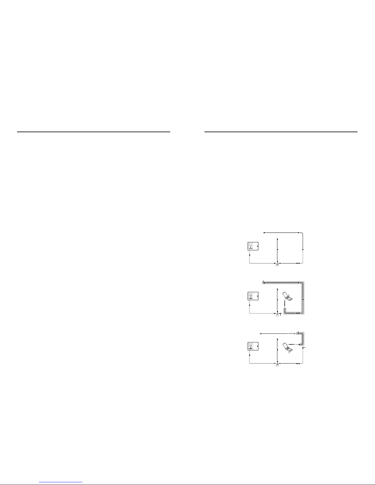
Investigating Leaks and Faults
If the location of a leak is not apparent, it is often useful to subdivide the leak detection
circuit, as illustrated below. To accomplish this, it is best to have a TraceTek Portable Test
Box (PTB) and an extra Modular End Termination. Contact your local TraceTek represen-
tative to obtain these products. Note that the PTB comes with instructions on its use.
To segment the system and isolate problems, find a TraceTek connection at a convenient
point somewhere at the center of the detection circuit. You can then use a PTB to check
one portion of the system (to verify circuit integrity, to detect the presence of liquid, and
even to determine its location). If you install an end termination on the other length of
cable (going back to the TTDM Alarm and Locating Module), you can use the TTDM to
check the “front half” of the sensing circuit.
You can further subdivide the circuit, and even test individual lengths of cables, as shown
in the third diagram below. Even the most perplexing problems can usually be isolated
and resolved using this methodical approach.
28 29
Cleaning the Module
To clean the outside surface, use a damp cloth or sponge. Do not use solvents or abrasive
cleaners, and do not open the enclosure while it is wet (it is an electrical device).
Fuse Replacement
The fuse on the power supply board (12 on foldout) is a 200-mA, 250-V, quick-acting
microfuse. It has an F1 rating, characteristic code F (quick-acting). Use no other type of
fuse or the TTDM could be damaged or could fail to perform properly.
Routine Maintenance
It is recommended that the TraceTek system be thoroughly checked twice a year. Such a
check will identify conditions that adversely affect the leak-locating capability of the sys-
tem. More frequent checks may be required if the sensing cable is repeatedly exposed to
leaks, or if construction or repair work is done where the sensing cable may be exposed.
Contact your local Raychem TraceTek representative for further information on service
support.
Storage and Handling of Sensing Cable
Despite their rugged construction, TraceTek sensing cables must be handled in a manner
appropriate for a sensing device or they may be damaged and require replacement.
Therefore, you should follow some basic rules for storing and handling all TraceTek
sensing cables:
• Store spare cable in its original container in a clean, dry place until ready
for installation.
• Schedule cable installation after all mechanical, plumbing, and electrical work has
been completed.
• Clean the area where the cable is to be installed, and remove any obvious debris or
other sources of contamination.
• Do not solder or weld near the cable without providing protection from heat, solder flux,
or weld splatter.
• Do not drop tools or floor tile on the cable; sharp and heavy objects may damage
the cable.
• Avoid walking or stepping on the cable. Provide shielding (for example, a half shell of
plastic pipe) where additional protection is necessary.
• Do not use tape to secure sensing cable (some tapes and adhesives absorb moisture)
or use solvents that could eventually cause an alarm.
• Do not drag sensing cable through contaminants (such as pipe dope, PVC cement,
solvents, oil, or dirt).
Appendix 3 - Maintenance
TTDM
Alarm and
Locating Module
End termination
End termination
End termination
End termination
PTB
PTB
To confirm that the scale is acceptable, use the “Leak” option in the 4–20 mA Test menu.
Simulate leaks at various locations, and verify that the output is as expected with the
equipment or instrument connected to the TTDM 4–20 output port.
Note: The maximum current output can be calibrated using trimpot R7 on the 4–20 mA
circuit board (8 on foldout).
Serial Port
The external communications port is configured for use as either RS-232 or RS-485. The
factory default is RS-232 full-duplex with no hardware handshaking.
This is suitable for connection to a remote host PC, laptop, serial printer, or modem. With
the appropriate cable and standard terminal software, a PC can receive time, communica-
tions, and Events History data.
One of the simplest but most important uses of the serial port is obtaining a printout of
the Events History log with a serial printer, or a PC with communications software.
Contact your Raychem TraceTek representative for additional information to assist in con-
necting and configuring for serial port communications.
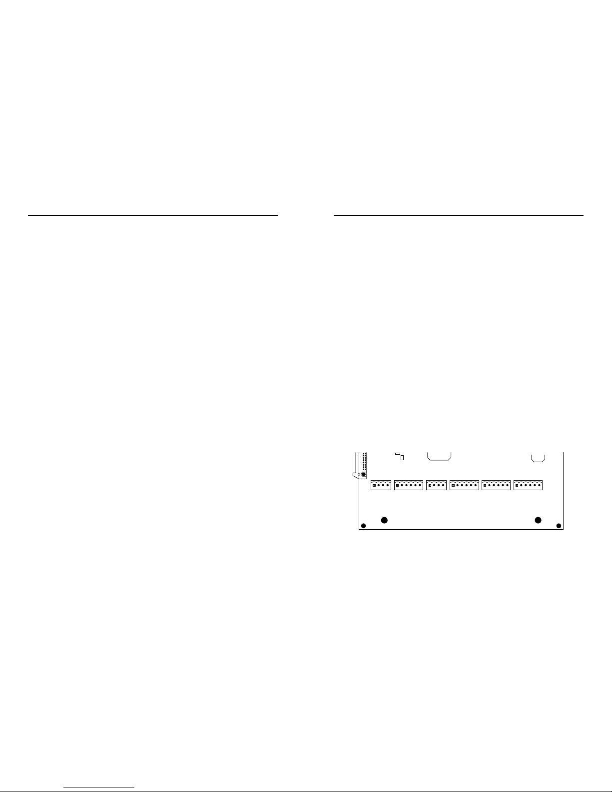
Connection Details
The illustration below shows the pinouts/terminals for the alarm relays, 4–20 mA port,
and RS-232/485 serial port. (labeled EXT COM PORT on the motherboard)
+51SO
1
PL
RS-485 EXT XMTRS
J10
PL
RS-232/485 EXT COM PORT
J13
PL
4-20MA OUT PORT
J2
SERVICE RELAY
5A 250V
J6
ALARM RELAY
5A 250V
J25
TROUBLE RELAY
5A 250V
J9
1 1 1 1 1
ICOM485+ 485–
1
2
3
4
RX/A TX/B RTS CTS +5V GND
5
6
7
8
9
10
IRTN IOUT +V +VRTN
11
12
13
14
NC NO COM NC NO COM
15
16
17
18
19
20
NC NO COM NC NO COM
21
22
23
24
25
26
NC NO COM NC NO COM
27
28
29
30
31
32
4–20 mA Current Transmitter
The TTDM adjusts its 4–20 mA output based on the leak detection status as detailed below.
Fault conditions:
Output (mA) Description
0 Electronic fault or loss of power
1.00 Fault—communications between SI and UI boards
2.00 Fault—cable break
3.00 Fault—cable damage (loop imbalance)
3.50 Service Required alarm
Normal conditions and leaks:
4.00 System normal
5.00 - 20.00 Leak; value scaled to indicate location of leak
Testing
When external equipment is connected to the TTDM 4–20 mA output port, the current
loop can be tested using the “4–20 mA Test” series under the Self-Test Menu. Before
doing so, confirm that all connections have been made, including 24 Vdc to TTDM
terminals 13 and 14. To conduct the 4–20 port tests, make the following menu selections,
beginning from the Main Menu: “View/Edit Settings,” “Self-Test Menu,” “4–20 mA Test.”
The entries in the 4–20 mA Test Menu are:
Electronics Fault
SI Comm Error
Cable Break
Loop Imbalance
Service Req’d
System Normal
Leak (a submenu prompts for a location to simulate)
20 mA Val
All but the last entry simulate the conditions noted; the TTDM changes its current output to that
designated for the condition selected (for example, 3.50 mA for a Service Required alarm).
Adjusting the Scale
Default value for the upper bound (i.e. the location that would result in the maximum cur-
rent output of 20 mA) is 5000 ft. (1500 m). To change the scale, select “20 mA Val” at the
bottom of the “4–20 mA Test” menu. Then enter a new upper bound to provide a reasonable
scale for your system.
Important: The upper bound must be greater than the Test Length (which the TTDM
displays in the System Status screen).
30 31
Appendix 4 - Interface Details

TTDM Operation Diagram
The TTDM measures resistance of
each circuit loop independently to
ensure the integrity of the circuit.
The resistance of the yellow-black
loop is used to compute the “Test
Length” displayed in the System
Status screen; it is based on a
real-time measurement.
The TTDM measures current
“leakage” between the two sensing
loops. When a leak is present, the
TTDM limits the current to 270
microamps, and measures the
voltage difference between the
yellow and black wires. The resis-
tance along the black sensing wire
to the leak is determined by a
simple application of Ohm’s law
(R = V/I). The resistance per unit
length of the sensing wire is tightly
controlled in manufacturing, so
this location is easily computed.
33
Appendix 6 - TraceTek Technical Data
RRG RYB
End
termination
End
termination
Loop resistances and test length
Sensing
cable
TTDM
DVLeak DVLocation
Leak current, resistance, location
Sensing
cable
TTDM Current
RLocation
RS-to-S
Red Green Yellow Black
Red Green Yellow Black
Relay wiring options
The illustrations below show how relays (15, 16, and 17 on foldout) can be jumpered
together to allow remote monitoring of the TTDM status with only a single pair of wires.
The TTDM
de-energizes
its relays to signal an alarm condition. Therefore, loss of power
as well as any other type of alarm would trip the remote alarm.
Alarm on open circuit
Alarm on closed circuit
SERVICE RELAY
5A 250V
J6
LEAK RELAY
5A 250V
J25
FAULT RELAY
5A 250V
J9
1 1 1
NC NO COM NC NO COM
15
16
17
18
19
20
NC NO COM NC NO COM
21
22
23
24
25
26
NC NO COM NC NO COM
27
28
29
30
31
32
Monitoring circuit
(alarm on closed circuit)
Relays wired
in parallel
SERVICE RELAY
5A 250V
J6
LEAK RELAY
5A 250V
J25
FAULT RELAY
5A 250V
J9
1 1 1
NC NO COM NC NO COM
15
16
17
18
19
20
NC NO COM NC NO COM
21
22
23
24
25
26
NC NO COM NC NO COM
27
28
29
30
31
32
Monitoring circuit
(alarm on open circuit)
Relays wired
in series
32
Appendix 5 - Wiring Details
This manual suits for next models
2
Table of contents
Other Raychem Control Unit manuals


Popular Control Unit manuals by other brands


Quectel
Quectel RM502Q-GL Hardware design

Burkert
Burkert 8791 REV.2 operating instructions

M-system
M-system R30CT4E instruction manual

Whelen Engineering Company
Whelen Engineering Company WPA Series installation guide

E-T-A
E-T-A ControlPlex EM12D-TIO user manual

Applied Motion Products
Applied Motion Products ST10-S Hardware manual


