Raydon RA-530 Series User manual

Multi
© RAYDON Electronics
RAYDON Electronics
RA-530 Series
(RA-531, RA-532, RA-535)
Multi
-C annel Laptop PC Battery
C arger and Re-conditioner
User Manual
V1.05
© RAYDON Electronics
Tec nology Co., Ltd.
All rig ts reserved
R
RA
AY
YD
DO
ON
N

This document Version complies with the Program revision 3.0x. The Manual and Software contain confidential
information which represents trade secrets of RA DON Electronics and may not be copied or disclosed except
as provided in the license with RA DON Electronics.
The information in this document is subject to change without notice and should not be construed as a
commitment by RA DON Electronics. RA DON Electronics assumes no responsibility for any errors that may
occur in this document.
All brand or product names are trademarks or registered trademarks of their respective holders.
Version Control
Version Description Date
V1.00 Draft, Chinese Version 18 Feb 2011
V1.01 Draft, English Version 10 Mar 2011
V1.02 Reviewed & dded ppendix for Database Download 26 pr 2011
V1.03 Modified Battery Selection method 29 Jun 2011
V1.04 dded utilities software descriptions 14 Nov 2012
V 1.05 dded buzzer and fan controls 28 Feb 2013
V1.06 dded Search and uto Update 20 ug 2013
Notices

RAYDON Electronics Technology Co., Ltd.
Phone: +86 20 8478 1227 Fax: +86 20 3478 1237
Web Site: http://www.batterytesting.com.cn
eMail: b[email protected]
Page 1 of 70 Pages
R
RR
R
R
RR
RA
AA
A
A
AA
AY
YY
Y
Y
YY
YD
DD
D
D
DD
DO
OO
O
O
OO
ON
NN
N
N
NN
N
CONTENTS
1. Introduction........................................................................................................................................................... 3
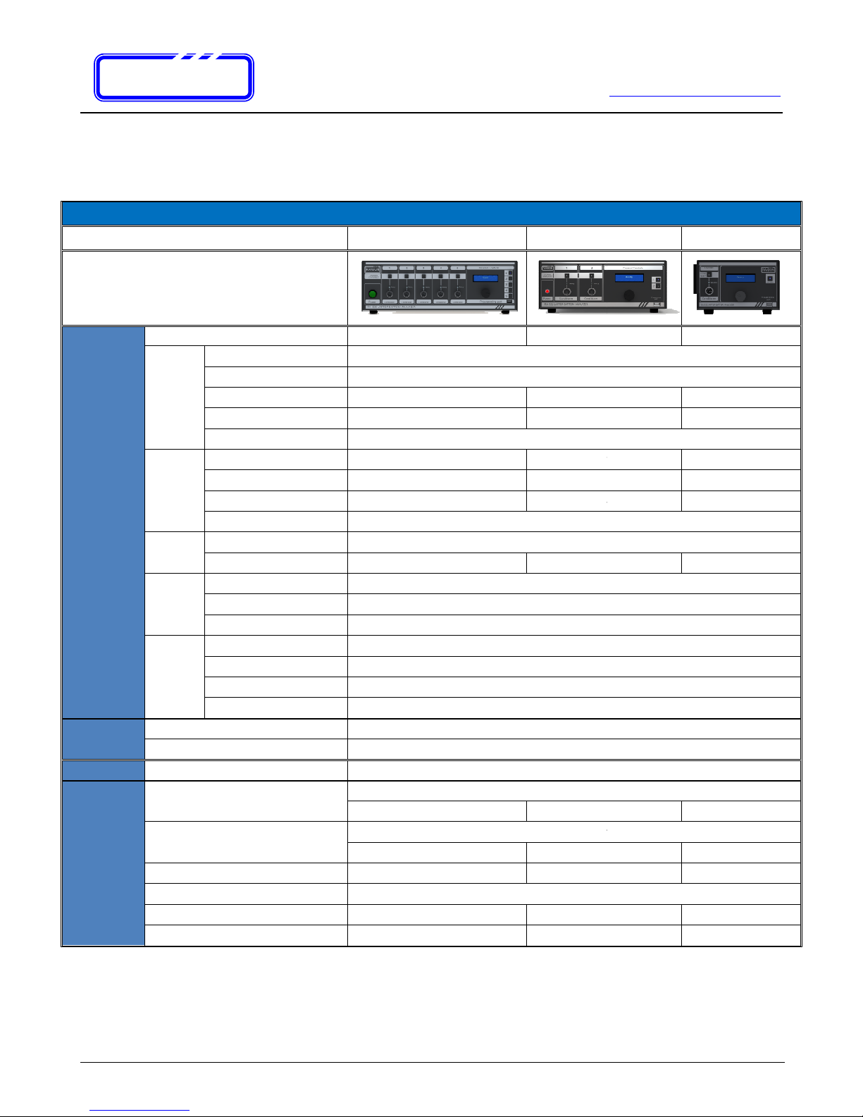
1.1. Product Description ...................................................................................................................................... 3
1.2. Features ....................................................................................................................................................... 4
1.3. Specification ................................................................................................................................................. 5
1.4. Testing Methodology .................................................................................................................................... 6
1.4.1. Pre-Charge ...................................................................................................................................... 6
1.4.2. Waken Charge ................................................................................................................................ 6
1.4.3. Storage Charge ............................................................................................................................... 6
1.4.4. High Charge .................................................................................................................................... 6
1.4.5. Discharge ........................................................................................................................................ 6
1.4.6. Capacity Test ................................................................................................................................... 7
1.4.7. Battery Performance Recovering Cycle - Re-Learning Cycle ........................................................ 7
2. Hardware Introduction ........................................................................................................................................... 8
2.1. Front Panel ................................................................................................................................................... 8
2.1.1. Power Area ...................................................................................................................................... 9
2.1.2. Channel Operational Area ............................................................................................................. 10
2.1.3. Channel Controls Area .................................................................................................................. 11
2.2. Rear Panel .................................................................................................................................................. 12
2.3. ccessories ................................................................................................................................................ 14
2.4. Hardware Installation and Start up ............................................................................................................... 15
2.4.1. Power Connections ....................................................................................................................... 15
2.4.2. Power ON ...................................................................................................................................... 16
3. Operation Guide .................................................................................................................................................. 17
3.1. Introduction to Button Controls ................................................................................................................... 17
3.1.1. Dial Button ..................................................................................................................................... 17
3.1.2. Channel Selection Buttons ............................................................................................................ 18
3.1.3. Channel Start/Reset Button .......................................................................................................... 19
3.2. Channel Operations .................................................................................................................................... 20
3.2.1. Overview ....................................................................................................................................... 20
3.2.2. Battery Selection ........................................................................................................................... 21
3.2.3. Input by Model ............................................................................................................................... 21
3.2.4. Input by Index ................................................................................................................................ 23
3.2.5. Select by “From History” ............................................................................................................... 24
3.2.6. Connector & Polarity Indication .................................................................................................... 25
3.2.7. SMBus Parameters Checking ....................................................................................................... 27
3.2.8. Test Schemes Selection Menu...................................................................................................... 30
3.2.9. Start Test with automatic Pre- Charge .......................................................................................... 31
3.2.10. Testing Status Displays ................................................................................................................. 32
3.2.11. Test Finish and Result Display ...................................................................................................... 34
. Trouble S ooting .................................................................................................................................................. 35
4.1. Battery LED OFF .......................................................................................................................................... 35
4.2. SMBus Read N/ ......................................................................................................................................... 35
4.3. Testing information display N/ ................................................................................................................... 36

RAYDON Electronics Technology Co., Ltd.
Phone: +86 20 8478 1227 Fax: +86 20 3478 1237
Web Site: http://www.batterytesting.com.cn
eMail: b[email protected]
Page 2 of 70 Pages
R
RR
R
R
RR
RA
AA
A
A
AA
AY
YY
Y
Y
YY
YD
DD
D
D
DD
DO
OO
O
O
OO
ON
NN
N
N
NN
N
4.4. Test abort abnormally ................................................................................................................................. 36
5. RA-530 Report & Tools Software ........................................................................................................................... 37
5.1. Computer Requirements ............................................................................................................................. 37
5.2. Software Installation ................................................................................................................................... 38
5.3. Connect to Computer .................................................................................................................................. 44
5.4. Instant Report Generator ............................................................................................................................ 47
5.4.1. Enter into Instant Report Generator .............................................................................................. 48
5.4.2. Instant Report Generator Interfaces ............................................................................................. 49
5.4.3. Steps to Generate a Report .......................................................................................................... 51
5.4.4. Report Sample .............................................................................................................................. 55
5.5. Battery Database Download ........................................................................................................................ 56
5.5.1. Enter into Database Download ..................................................................................................... 56
5.5.2. Battery Database Download Interfaces ........................................................................................ 57
5.5.3. Steps to Download Battery Database ........................................................................................... 59
5.6. Search Laptop model & Battery Model Information ................................................................................. 62
5.6.1. Enter into Battery information Search ........................................................................................... 62
5.6.2. Battery Information Search Generator Interfaces ......................................................................... 63
5.6.3. Select Search By Laptop Model.................................................................................................... 64
5.6.4. Search By Battery Model .............................................................................................................. 65
5.7. Auto Update ............................................................................................................................................. 66
Appendix II: Battery Models List ................................................................................................................................... 68

RAYDON Electronics Technology Co., Ltd.
Phone: +86 20 8478 1227 Fax: +86 20 3478 1237
Web Site: http://www.batterytesting.com.cn
eMail: b[email protected]
Page 3 of 70 Pages
R
RR
R
R
RR
RA
AA
A
A
AA
AY
YY
Y
Y
YY
YD
DD
D
D
DD
DO
OO
O
O
OO
ON
NN
N
N
NN
N
1. Introduction
1.1.
Product Description
R -530 series (531, 532, 535) laptop battery pack analyzer is Multi-channels laptop PC battery charging and reconditioning
equipment designed especially as an ideal charging station and maintenance tool for laptop PC retailers, corporate facilities,
laptop repair centers and educational institutions who have a lot of batteries to maintain over the period.
Normally, users can only charge and discharge their laptop battery through the laptop. Laptop batteries also have various
kind of PIN connection design that users are impossible to work on these batteries. R -530 series (531, 532, 535) analyzer
has most of the laptop battery database build-in its internal memory. It reduces the requirement of technical knowhow
toward the laptop batteries.
Each R -530 series (531, 532, 535) analyzer can store up to 1,000 set of laptop battery database and there is virtually no
limitation in the battery models expansion. Latest database can be downloaded to the tester through the programming port
in the front panel. This is a good protection to user’s investment.
R -530 series (531, 532, 535) analyzer contains two kinds of laptop battery testing channels:
Charging Channel
Reconditioning Channel
s an daily maintenance tool, the Charging channel allows the user to re-charge the stock laptop batteries over a constant
period, a regular practice helps to reduce RM over 60% as the most popular cause of laptop battery faulty is due to self
discharge of prolong storage of the un-use battery.
Reconditioning channel helps to re-synchronize the laptop battery cell status with the information stored in the battery
circuitry. User should perform the reconditioning of the battery in a regular base or once they find the performance of their
laptop battery has drop significantly.
For standard delivery configuration, R -530 series (531, 532, 535) analyzer provides 1, 2, 5 reconditioning channel
respectively. However, flexible channel combinations and configuration can be ordered to fit different requirements. User
can choose from reconditioning channel or charging channel independently to meet their needs.
Designed and produced by R YDON Electronics who has years of experience in Laptop battery testing, The R -530 series
(531, 532, 535) analyzer provides comprehensive functions and database, and there is no matching product available in the
market.

RAYDON Electronics Technology Co., Ltd.
Phone: +86 20 8478 1227 Fax: +86 20 3478 1237
Web Site: http://www.batterytesting.com.cn
eMail: b[email protected]
Page 4 of 70 Pages
R
RR
R
R
RR
RA
AA
A
A
AA
AY
YY
Y
Y
YY
YD
DD
D
D
DD
DO
OO
O
O
OO
ON
NN
N
N
NN
N
1.2.
Features
Ideal charging station and maintenance tool for laptop PC retailers, corporate facilities, laptop repair centers and
educational institutions
Stand-alone design with built-in battery database
Completely isolated channels for separate operations at the same time
Simple user interfaces with LCD display and dial button design, no battery knowledge is required – Just dial, select
and Go!
Multiple charging schemes, high charge or storage charge, for selected purposes
dditional reconditioning channel for battery maintenance and improved battery performance
utomatically activates sleeping batteries before charging or reconditioning
Build-in simple SMBus diagnostic display allows user to determine the faulty cause and actions
Display battery critical data when action, helps the user to monitor the testing progress
Display individual cell voltage during testing allows user can check for cell balancing
Each channel has its own memory to store selected Test Scheme. It allows same model of batteries to be tested
under the same channel, without repeat the setting procedures.
Build-in protection features against over-charged, under-charged, over-current and short circuit.
Double watch-dog design (software and hardware) to ensure battery safety during charging and reconditioning.
External Programming port allows latest database update
Reconditioning Channel (Standard delivery):
Waken (combinations of small charge/discharge current to activate faulty batteries)
High Charge (charge battery to 93%
~
100%, ready to be used immediately)
Storage Charge (charge battery to approximately 60%, designed for safe battery storage)
Discharge (for over-charged battery)
Capacity Test (for capacity verifications)
Learning Cycle (for periodic maintenance)
Charging Channel (Optional):
Waken Charge (apply small charge current to activate faulty batteries)
High Charge (charge battery to 93%
~
100%, ready to be used immediately)
Storage Charge (charge battery to approximately 60%, designed for safe battery storage)
Provide different kinds of connectors to support most of the popular laptop battery models in the market
Energy-saving mode enables the tester to go into sleeping mode after 3 minutes into idle stage with fan and LCD
display turn off.
User can select to turn ON or OFF the buzzer operation

R
RR
R
R
RR
RA
AA
A
A
AA
AY
YY
Y
Y
YY
YD
DD
D
D
DD
DO
OO
O
O
OO
ON
NN
N
N
NN
N
1.3.
Specification
C arge
and
Reconditioning
Number of C annels
Constant
Current
Mode
(CC)
Charge Current Range
Discharge Current
Range
Current Resolution
Current ccuracy
Maximum Voltage Load
Constant
Voltage
Mode
(CV)
Voltage Output Range
Voltage Resolution
Voltage ccuracy
Maximum Current
Capacity
Capacity Measuring Range
Capacity ccuracy
SMBus
Support
(SMR)
Numerical Parameter
String Parameters
Compatibility
Timer
Control
Fully Chg/Dchg max. time
Condition Learning max.
time
Storage max time
Waken max time
Laptop Battery
Compatibility
Battery Voltage:
Battery Capacity:
LCD Display Display Words:
Ot ers
Input :
Output :
Max. Power Consumption :
Working Ambiant Temperature :
Dimensions (H x W x D) :
Net Weig t (Approximate) :
RAYDON Electronics Technology Co., Ltd.
Phone: +86 20 8
478 1227
Web Site:
eMail:
batterytesting@batterytesting.com.cn
SPECIFIC TIONS
R
-
535
R
-
532
5 2
0.01~4.99
Range
0.01~4.99
5m
5m
±(1%+20m )
±(1%+20m )
17.99V
0.01~17.99V
0.01~17.99V
5mV
5mV
±(0.5%+10mV)
±(0.5%+10mV)
4.99
Capacity Measuring Range
0~9999m H
±(1%+20m H)
±(1%+20m H)
Cycle Count,
FCC, RSOC, Voltage, Cell Voltages
None
SMB
1.0 and 1.1
4 hours
time
7 hours
2 hours
1 hour
7.2 ~ 14.8 V
1000 ~ 8800 m h
16 × 2
100 ~ 240 V C 50
/ 60
2 ~ 4
1 ~ 2
8.4 / 12.6 /
16.8 VDC
5 Max. 5
Max.
450 W
180 W
0 ºC ~ 45 ºC
140 x 420 x 360 mm
110 x 290 x280mm
10 Kg
5 Kg
RAYDON Electronics Technology Co., Ltd.
478 1227
Fax: +86 20 3478 1237
Web Site:
http://www.batterytesting.com.cn
Page 5 of 70 Pages
532
R -531
1
5m
10m
±(1%+20m )
±(1.5%+30m )
0.01~17.99V
0.01~17.99V
5mV
10mV
±(0.5%+10mV)
±(0.8%+20mV)
±(1%+20m H)
±(1.5%+30m H)
FCC, RSOC, Voltage, Cell Voltages
1.0 and 1.1
1000 ~ 8800 m h
/ 60
Hz
1 ~ 2
0.5~ 1
16.8 VDC
Max.
4 Max.
180 W
90 W
110 x 290 x280mm
110 x 180 x 210 mm
5 Kg
2Kg

RAYDON Electronics Technology Co., Ltd.
Phone: +86 20 8478 1227 Fax: +86 20 3478 1237
Web Site: http://www.batterytesting.com.cn
eMail: b[email protected]
Page 6 of 70 Pages
R
RR
R
R
RR
RA
AA
A
A
AA
AY
YY
Y
Y
YY
YD
DD
D
D
DD
DO
OO
O
O
OO
ON
NN
N
N
NN
N
1. .
Testing Met odology
1. .1. Pre-C arge
In order to stabilize the testing battery, a pre-charge step is introduced at the start of all steps in each
methodology automatically. The system will apply a small charging current (200m ) for 5 minutes.
1. .2. Waken C arge
Small current rate is used to charge the battery pack. It will not check for the output current since some batteries
will not allow any current flow during the initial stage. The Waken Recover will be self terminated in programmed
time.
Step description:
Step Type Mode Set Value Current Output Terminate Conditions
1 Charge CV 4V/cell 200m Programmed time
1. .3. Storage C arge
Single charge step to charge the battery pack to normal operational status.
Step description:
Step Type Mode Set Value Current Output Terminate Conditions
1 Charge CC 0.5 C 0.5C Volt > 4.1V/cell
1. . . Hig C arge
Single charge step to charge the battery pack to above 93% charged state.
Step description:
Step Type Mode Set Value Current Output Terminate Conditions
1 Charge CV 0.5 C 0.5C Current < 0.02C
1. .5. Disc arge
Single discharge step to discharge the battery pack to near empty state, user can terminate the test at any time to
achieve required battery level.
Step description:
Step Type Mode Set Value Current Output Terminate Conditions
1 Discharge
CC 0.5 C 0.5C Volt < 3.0V/cell

RAYDON Electronics Technology Co., Ltd.
Phone: +86 20 8478 1227 Fax: +86 20 3478 1237
Web Site: http://www.batterytesting.com.cn
eMail: b[email protected]
Page 7 of 70 Pages
R
RR
R
R
RR
RA
AA
A
A
AA
AY
YY
Y
Y
YY
YD
DD
D
D
DD
DO
OO
O
O
OO
ON
NN
N
N
NN
N
1. .6. Capacity Test
Two steps process to fully charge and then fully discharge the battery pack with medium current rate and display
the battery’s capacity value at the last result display screen.
Step description:
Step Type Mode Set Value Current Output Terminate Conditions
1 Charge CV 4.2V/cell 0.5C Current < 0.05C
2 Discharge
CC 0.5C 0.5C Volt < 3.0V/cell
1. .7. Battery Performance Recovering Cycle - Re-Learning Cycle
Four steps process to re-learn the battery pack with medium current rate and update the battery’s FCC value to its
accurate level.
Step description:
Step Type Mode Set Value Current Output Terminate Conditions
1 Discharge
CC 0.5 C
0.5C
Volt < 3.0V/cell
2 Charge CV 4.2V/cell
0.5C
Current < 0.05C
3 Discharge
CC 0.5C
0.5C
Volt < 3.0V/cell
4 Charge CV 4.2V/cell
0.5C
Volt > 4.1V/cell

R
RR
R
R
RR
RA
AA
A
A
AA
AY
YY
Y
Y
YY
YD
DD
D
D
DD
DO
OO
O
O
OO
ON
NN
N
N
NN
N
2. Hardware Introduction
2.1.
Front Panel
The following picture illustrates
the front panel of the
The following picture illustrates
the front panel of the
RAYDON Electronics Technology Co., Ltd.
Phone: +86 20 8
478 1227
Web Site:
eMail:
batterytesting@batterytesting.com.cn
the front panel of the
R -535:
the front panel of the
R -532:
RAYDON Electronics Technology Co., Ltd.
478 1227
Fax: +86 20 3478 1237
Web Site:
http://www.batterytesting.com.cn
Page 8 of 70 Pages

R
RR
R
R
RR
RA
AA
A
A
AA
AY
YY
Y
Y
YY
YD
DD
D
D
DD
DO
OO
O
O
OO
ON
NN
N
N
NN
N
The following picture illustrates
the front panel of the
2.1.1. Power Area
Power
RAYDON Electronics Technology Co., Ltd.
Phone: +86 20 8
478 1227
Web Site:
eMail:
batterytesting@batterytesting.com.cn
the front panel of the
R -531:
RA
RARA
RA
-
--
-
535
535535
535
Power Switch
Power SwitchPower Switch
Power Switch
A large LED and button
is used to indicate
the POWER ON status of the
RAYDON Electronics Technology Co., Ltd.
478 1227
Fax: +86 20 3478 1237
Web Site:
http://www.batterytesting.com.cn
Page 9 of 70 Pages
is used to indicate
tester

RAYDON Electronics Technology Co., Ltd.
Phone: +86 20 8478 1227 Fax: +86 20 3478 1237
Web Site: http://www.batterytesting.com.cn
eMail: b[email protected]
Page 10 of 70 Pages
R
RR
R
R
RR
RA
AA
A
A
AA
AY
YY
Y
Y
YY
YD
DD
D
D
DD
DO
OO
O
O
OO
ON
NN
N
N
NN
N
2.1.2. C annel Operational Area
1
Conditioner
Battery
Channel
Channel Channel
Channel Start/Reset
Start/ResetStart/Reset
Start/Reset
Button and
Button and Button and
Button and Status LED
Status LEDStatus LED
Status LED
Channel Status LED:
1. Ready: OFF
2. Testing: ON
3. Stopped: Flash
utton Functions:
1. Press once when:
Ready: Start the stored procedure directly
Stopped: Returns to Ready State
Editing: N/A (When editing in the Channel Control Area)
2. Press over 3 Seconds when:
Testing: Stop current procedure immediately
Battery
Battery Battery
Battery Status
Status Status
Status LED
LEDLED
LED
1. Green ON: Normal battery voltage detected
2. Red ON: Any of the following errors:
attery polarity error;
Detected sleeping attery, Waken Charging;
Detected battery voltage < 1V/cell after
Wakening;
Faulty condition during testing
3. OFF: No battery is detected
C
CC
Channel
hannelhannel
hannel
Port
PortPort
Port
Only use the battery cable provided to connect
the battery with the Analyzer. The cable and port
are keyed. Match up the keys to ensure a proper
connection.
Channel Number
Channel NumberChannel Number
Channel Number
Channel Type
Channel TypeChannel Type
Channel Type
Two types of Channel are available:
1. Charger
2. Conditioner

RAYDON Electronics Technology Co., Ltd.
Phone: +86 20 8478 1227 Fax: +86 20 3478 1237
Web Site: http://www.batterytesting.com.cn
eMail: b[email protected]
Page 11 of 70 Pages
R
RR
R
R
RR
RA
AA
A
A
AA
AY
YY
Y
Y
YY
YD
DD
D
D
DD
DO
OO
O
O
OO
ON
NN
N
N
NN
N
2.1.3. C annel Controls Area
USB
USB USB
USB Programming Port
Programming PortProgramming Port
Programming Port
Provide connection to any Windows
based computer. With provided software
tools, user can:
Extract test result information
and product an instant report for
future reference.
Download/Update battery testing
database from PC into tester’s
memory
LCD
LCDLCD
LCD
Display and Dial Button
Display and Dial ButtonDisplay and Dial Button
Display and Dial Button
LCD Display:
16 x 2 Characters
Display selected Channel Informa
tion
Dial utton:
Dial to change display pages
Press to select or enter
Channel Select
Channel SelectChannel Select
Channel Selection
ionion
ion
Button with LED)
Button with LED)Button with LED)
Button with LED)
Press respective button to select
Channel for control. LED of the
selected button is ON to indicate
Channel is selected.
Can also be used as a cancel button
during editing, press the same
selected channel button, all editing
will be cancelled and return to ready
state.
Programming Port
Channel Controls
1
2
3
5

RAYDON Electronics Technology Co., Ltd.
Phone: +86 20 8478 1227 Fax: +86 20 3478 1237
Web Site: http://www.batterytesting.com.cn
eMail: b[email protected]
Page 12 of 70 Pages
R
RR
R
R
RR
RA
AA
A
A
AA
AY
YY
Y
Y
YY
YD
DD
D
D
DD
DO
OO
O
O
OO
ON
NN
N
N
NN
N
2.2.
Rear Panel
The following picture illustrates the rear panel of the R -535
Power Section:
1 - Power Fuse
2 - Power Cable In
3 - Power Switch
4 - Line Voltage Setting Switch
Ex aust Fan Section:
5 - Exhaust Fan Outlet
6 - Rear Panel Channel Ports (Optional, disabled in standard delivery. Please contact our sales representative)

RAYDON Electronics Technology Co., Ltd.
Phone: +86 20 8478 1227 Fax: +86 20 3478 1237
Web Site: http://www.batterytesting.com.cn
eMail: b[email protected]
Page 13 of 70 Pages
R
RR
R
R
RR
RA
AA
A
A
AA
AY
YY
Y
Y
YY
YD
DD
D
D
DD
DO
OO
O
O
OO
ON
NN
N
N
NN
N
The following picture illustrates the rear panel of the R -532
Power Section:
1 - Power Fuse
2 - Power Cable In
3 - Power Switch
4 - Line Voltage Setting Switch
Ex aust Fan Section:
5 - Exhaust Fan Outlet
The following picture illustrates the rear panel of the R -531
Power Section:
1 - Power Fuse
2 - Power Cable In
3 - Power Switch

RAYDON Electronics Technology Co., Ltd.
Phone: +86 20 8478 1227 Fax: +86 20 3478 1237
Web Site: http://www.batterytesting.com.cn
eMail: b[email protected]
Page 14 of 70 Pages
R
RR
R
R
RR
RA
AA
A
A
AA
AY
YY
Y
Y
YY
YD
DD
D
D
DD
DO
OO
O
O
OO
ON
NN
N
N
NN
N
2.3.
Accessories
The following accessories are included in the standard package:
Description QTY Pictures
• Power Cable 1
• Standard Testing Cables for R -535 5
• Standard Testing Cables for R -532 2
• Standard Testing Cables for R -531 1
• PC communications:
USB to Communications Cable
Installation CD
• User Manual 1
• Calibration Report 1
The following Accessories are optional, user can order according to their needs:
Optional Accessories Pictures
• RD series Battery Connectors
• RM series Universal Connectors

RAYDON Electronics Technology Co., Ltd.
Phone: +86 20 8478 1227 Fax: +86 20 3478 1237
Web Site: http://www.batterytesting.com.cn
eMail: b[email protected]
Page 15 of 70 Pages
R
RR
R
R
RR
RA
AA
A
A
AA
AY
YY
Y
Y
YY
YD
DD
D
D
DD
DO
OO
O
O
OO
ON
NN
N
N
NN
N
2. .
Hardware Installation and Start up
2. .1. Power Connections
Follow the steps below to power up the R -530 series analyzer:
1. Before plugging in the power cable of the analyzer, be sure that the Power Switch in the front Panel is set as OFF.
2. Due to different Line Voltage supplies in different countries, Users must adjust the “Line Voltages Setting Switch”
accordingly. Please make sure the line switch is set according to the Line Voltage:
Line Voltage: 100Vac to 120Vac
Please select 115V Setting
Line Voltage: 200Vac to 240Vac
Please select 230V Setting
3. Plug in the Power Cable provided in the package.
4. Double check the Line Voltage setting before turn on the Power Switch.

R
RR
R
R
RR
RA
AA
A
A
AA
AY
YY
Y
Y
YY
YD
DD
D
D
DD
DO
OO
O
O
OO
ON
NN
N
N
NN
N
2. .2. Power ON
fter connected the Line Power and adjusted the
located at the left hand side of the
front panel.
before turning on the power.
When the power is ON, LED in the green
Power
t this time check the all other LEDs on the front panel should be OFF, except Channel Selection Button for Channel #1,
which indicates channel 1 is selected as default.
display will show as following:
When it is done, the LCD display will show the status of Channel #1 on its screen. Check Section 3.2 for further operations.
!
!!
!
Please make sur
e that there is no battery
before turning on the power switch.
!
!!
!
If LCD displays un-
recognizable
O again. If the
situation persists
personnel to check the Line Voltage with a DMM. ormally this will happen
when Line Voltage drops below 100Vac.
RAYDON Electronics Technology Co., Ltd.
Phone: +86 20 8
478 1227
Web Site:
eMail:
batterytesting@batterytesting.com.cn
fter connected the Line Power and adjusted the
“Line Voltages Setting Switch”
, user may now turn on the Power Switch
front panel.
Please make sure that there is no battery
connected to any of the channel
Power
Switch will turn on
to indicate the power is ON.
t this time check the all other LEDs on the front panel should be OFF, except Channel Selection Button for Channel #1,
which indicates channel 1 is selected as default.
BTI-850B
should go through an initialization stage, at this stage, the LCD
When it is done, the LCD display will show the status of Channel #1 on its screen. Check Section 3.2 for further operations.
READY
e that there is no battery
connected to any of the channel
before turning on the power switch.
recognizable
characters, please turn the power OFF and
situation persists
, please ask your electricity
personnel to check the Line Voltage with a DMM. ormally this will happen
when Line Voltage drops below 100Vac.
RAYDON Electronics Technology Co., Ltd.
478 1227
Fax: +86 20 3478 1237
Web Site:
http://www.batterytesting.com.cn
Page 16 of 70 Pages
, user may now turn on the Power Switch
connected to any of the channel
to indicate the power is ON.
t this time check the all other LEDs on the front panel should be OFF, except Channel Selection Button for Channel #1,
should go through an initialization stage, at this stage, the LCD
When it is done, the LCD display will show the status of Channel #1 on its screen. Check Section 3.2 for further operations.
connected to any of the channel
characters, please turn the power OFF and
, please ask your electricity
technical
personnel to check the Line Voltage with a DMM. ormally this will happen

RAYDON Electronics Technology Co., Ltd.
Phone: +86 20 8478 1227 Fax: +86 20 3478 1237
Web Site: http://www.batterytesting.com.cn
eMail: b[email protected]
Page 17 of 70 Pages
R
RR
R
R
RR
RA
AA
A
A
AA
AY
YY
Y
Y
YY
YD
DD
D
D
DD
DO
OO
O
O
OO
ON
NN
N
N
NN
N
3. Operation Guide
3.1.
Introduction to Button Controls
3.1.1. Dial Button
Digital Dial Button is located at the centre of the Channel Control rea. It integrates item cursor controls and entry selection
in one device. User can dial up or down to display the select entries or page information on the LCD display. ll operations
can be simplified into three actions:
Clockwise Rotation : Menu Operation: Control cursor downward for menu entries selection
Testing Status: Show next page information
nti-clockwise Rotation : Menu Operation: Control cursor upward for menu entries selection
Testing Status: Show previous page information
Press : Menu Operation: Select menu entry or confirm action
Buzzer Control: Turn buzzer ON/OFF (Press for 3 Seconds)
Programming Port
Channel Controls
1
2
3
5
Dial
Button

RAYDON Electronics Technology Co., Ltd.
Phone: +86 20 8478 1227 Fax: +86 20 3478 1237
Web Site: http://www.batterytesting.com.cn
eMail: b[email protected]
Page 18 of 70 Pages
R
RR
R
R
RR
RA
AA
A
A
AA
AY
YY
Y
Y
YY
YD
DD
D
D
DD
DO
OO
O
O
OO
ON
NN
N
N
NN
N
3.1.2. C annel Selection Buttons
Channel Selection Buttons locate by the side of the LCD Display and each button has a number to indicate the according
channel. total of 5 Channel Selection Buttons are installed to represent the 5 available channels. When any of the buttons
is pressed, the LCD Display will show the channel information in respected to the channel number and the Dial Button will
be dedicated to the selected channel.
ll Channel Selection Buttons have build-in LED to indicate the selected channel. User can use these buttons to switch
controls among all 5 channels in the equipment.
The Channel Selection Buttons are also designed as C NCEL button to any dial button operation for that specific channel.
When press the same channel button during the operation, the channel will exit from the operation and return to RE DY
state.
Programming Port
Channel Controls
1
2
3
5
Channel
Selection
Button
This manual suits for next models
3
Table of contents