Ametek PRESTOLITE POWER EQUINOX User manual

OWNER’S MANUAL 193111-075
Revised October 20, 2008
IMPORTANT: Read these instructions before installing, operating, or
servicing this system.
Opportunity
Battery Charger
DO NOT DESTROY
AMETEK/PRESTOLITE POWER , TROY, OHIO 45373-1099, U.S.A.
EQUINOX

NOTE: Information regarding obtaining additional copies of this manual is located in the Introduction
chapter of this manual.
A battery charger is identified by model number. Incorporated into the model number is the maximum
power rating, and maximum number of cells in battery for which charger is intended. The following
example explains the basic model numbering arrangement.
Model PAC 320 24
Maximum Number of Cells
DC Current Rating (Amps)
Prestolite Advanced Charger (Hi-Frequency SMPS)
NOTE: This information is required for ordering certain replacement/service parts.

193111-075
TABLE OF CONTENTS
January 2, 2008 Revised
INTRODUCTION .....................................................................................................................................1
How To Use This Manual ...................................................................................................................1-1
Equipment Identification .....................................................................................................................1-1
Receipt Of Equipment ........................................................................................................................1-1
SAFETY INSTRUCTIONS AND WARNINGS ........................................................................... 2
DESCRIPTION OF EQUIPMENT .............................................................................................. 3
Operating Modes ................................................................................................................................3-1
Opportunity Charging .........................................................................................................................3-1
EQUINOX Control ..............................................................................................................................3-2
INSTALLATION ......................................................................................................................... 4
Location ..............................................................................................................................................4-1
Environmental Characteristics............................................................................................................4-1
Grounding...........................................................................................................................................4-1
Line Voltage Changeover Instructions ...............................................................................................4-2
Line Connections to Battery Charger .................................................................................................4-2
Charging Cable Connectors ...............................................................................................................4-3
Pre-operation Checks.........................................................................................................................4-3
Pre-Operation Changes to the Factory Control Settings....................................................................4-3
MAINTENANCE......................................................................................................................... 5
OPERATION .............................................................................................................................. 6
Preliminary..........................................................................................................................................6-1
Normal Or Daily Charge .....................................................................................................................6-1
Equalize Or Weekend Charge............................................................................................................6-2
Manual Stop .......................................................................................................................................6-2
AC Power Fail.....................................................................................................................................6-2
Abnormal Shutdowns .........................................................................................................................6-2
EQUINOX CONTROL FEATURES............................................................................................ 7
Main Features.....................................................................................................................................7-1
Description of Features ......................................................................................................................7-2
EQUINOX Charge Archive Function ..................................................................................................7-6
EQUINOX Charge Cycle Review Function ........................................................................................7-7
PROGRAMMING YOUR EQUINOX CONTROL ....................................................................... 8
Using Extended AH for Opportunity/Fast Charging ...........................................................................8-5
Multi Amp Hour Programming ............................................................................................................8-6
Timer Start Mode Programming .........................................................................................................8-7
OPTIONS ................................................................................................................................... 9
Series Charging..................................................................................................................................9-1
Remote Display Kit .............................................................................................................................9-1
Floor Mounting Stand .........................................................................................................................9-1
Archive Downloading Kit.....................................................................................................................9-2
Arcless Disconnect (Opt. 600)………………………...………….……………………………….………..9-2
Remote Stop Pushbutton Kit..…………………….…………...………………………………...…...…….9-2
PARTS LIST ............................................................................................................................ 10
DIAGRAMS
WARRANTY

1-1 April 26, 2007
193111-075
INTRODUCTION
INTRODUCTION
How To Use This Manual
IMPORTANT: It is especially
important that all charger
internal components be kept
clean and dry, and all
electrical connections
tightened. Replace any
precautionary or instruction
label that cannot be easily
read.
To ensure safe operation, read the entire manual,
including the chapter on safety instructions and
warnings.
Throughout this manual, the words WARNING,
CAUTION, and NOTE may appear. Pay particular
attention to the information provided under these
headings. These special annotations are easily
recognized as follows:
WARNING gives information
regarding possible personal
injury. Warnings will be
enclosed in a box such as this.
CAUTION refers to possible equipment
damage. Cautions will be shown in bold
type.
NOTE offers helpful information concerning
certain operating procedures. Notes will be
shown in italics.
Equipment Identification
The unit's identification number (specification, model,
serial number) usually appears on a nameplate
attached to the front panel.
Receipt Of Equipment
When you receive the equipment, check it against the
invoice to make sure it is complete and inspect the
equipment for possible damage due to shipping. If
there is any damage, notify the carrier immediately to
file a claim. Furnish complete information concerning
damage claims or shipping errors to the company
shown on the cover of this manual. Include all
equipment identification numbers and group part
numbers (if any) as described above along with a full
description of the parts in error.
Move the equipment to the site of installation before
uncrating. Use care to avoid damaging the equipment
when using bars, hammers, etc., to uncrate the unit.
Additional copies of this manual may be purchased by
contacting the company shown on the cover of this
manual. Include the Owner's Manual number and
equipment identification numbers.

April 26, 2007 2-1
193111-075
SAFETY INSTRUCTIONS AND WARNINGS
FOR OPERATION OF BATTERY
CHARGING EQUIPMENT
IMPORTANT – READ AND
UNDERSTAND THESE
INSTRUCTIONS. DO NOT
LOSE THEM. ALSO READ
OPERATING/INSTRUCTION
MANUAL BEFORE
INSTALLING, OPERATING,
OR SERVICING THIS
EQUIPMENT.
A. General
Battery charging products can cause serious
injury or death, or damage to other equipment or
property, if the operator does not strictly observe
all safety rules and take precautionary actions.
Safe practices have developed from past experience
in the use of charging equipment. These practices
must be learned through study and training before
using this equipment. Anyone not having
extensive training in battery charging practices
should be taught by experienced operators.
Only qualified personnel should install, use, or
service this equipment.
B. Shock Prevention
Bare conductors, or terminals in the output circuit,
or ungrounded, electrically-live equipment can
fatally shock a person. To protect against shock,
have competent electrician verify that the
equipment is adequately grounded and learn what
terminals and parts are electrically HOT.
Always wait one minute after de-energizing charger
before touching any interior components or connections.
The body’s electrical resistance is decreased when wet,
permitting dangerous current to flow through the body.
Do not work in damp area without being extremely
careful. Stand on dry rubber mat or dry wood and use
insulating gloves when dampness or sweat cannot be
avoided. Keep clothing dry.
1. Installation and Grounding of Electrically Powered
Equipment – Electrical equipment must be installed
and maintained in accordance with the National
Electrical Code, NFPA 70, and local codes. A
power disconnect switch must be located at the
equipment. Check nameplate for voltage and
phase requirements. If only 3-phase power is
available, connect single-phase equipment to only
two wires of the 3-phase line. DO NOT CONNECT
the equipment grounding conductor (lead) to the
third live wire of the 3-phase line as this makes the
equipment frame electrically HOT, which can cause
a fatal shock.
If a grounding lead (conductor) is part of the power
supply cable, be sure to connect it to a properly
grounded switch box or building ground. If not part
of the supply cable, use a separate grounding lead
(conductor). Do not remove a ground prong from
any plug. Use correct mating receptacles. Check
ground for electrical continuity before using
equipment.
The grounding conductor must be of a size equal
to or larger than the size recommended by Code or
in this manual.
2. Charging Leads – Inspect leads often for damage
to the insulation. Replace or repair cracked or worn
leads immediately. Use leads having sufficient
capacity to carry the operating current without
overheating.
3. Battery Terminals – Do not touch battery terminals
while equipment is operating.
4. Service and Maintenance – Shut OFF all power at
the disconnect switch or line breaker before
inspecting, adjusting, or servicing the equipment.
Lock switch OPEN (or remove line fuses) so that
the power cannot be turned ON accidentally.
Disconnect power to equipment if it is to be left
unattended or out of service.
Disconnect battery from charger.
Keep inside parts clean and dry. Dirt and/or
moisture can cause insulation failure. This failure
can result in high voltage at the charger output.

193111-075
SAFETY INSTRUCTIONS AND WARNINGS
2-2 April 26, 2007
C. Burn and Bodily Injury Prevention
The battery produces very high currents when short
circuited, and will burn the skin severely if in contact
with any metal conductor that is carrying this current.
Do not permit rings on fingers to come in contact with
battery terminals or the cell connectors on top of the
battery.
Battery acid is very corrosive. Always wear correct eye
and body protection when near batteries.
D. Fire and Explosion Prevention
Batteries give off explosive flammable gases which
easily ignite when coming in contact with an open flame
or spark. Do not smoke, cause sparking, or use open
flame near batteries. Charge batteries only in
locations which are clean, dry, and well ventilated.
Do not lay tools or anything that is metallic on top of any
battery. All repairs to a battery must be made only by
experienced and qualified personnel.
E. Arcing and Burning of Connector
To prevent arcing and burning of the connector
contacts, be sure the charger is OFF before connecting
or disconnecting the battery. (If the charger is equipped
with an ammeter, the ammeter should not indicate
current flow.) Always make sure charger output if off
before connecting battery.
F. Medical and First Aid Treatment
First aid facilities and a qualified first aid person should
be available for each shift for immediate treatment of
electrical shock victims.
EMERGENCY FIRST AID: Call
physician and ambulance
immediately. Use First Aid
techniques recommended by the
American Red Cross.
DANGER: ELECTRICAL SHOCK
CAN BE FATAL. If person is
unconscious and electric shock
is suspected, do not touch
person if he or she is in contact
with charging leads, charging
equipment, or other live electrical
parts. Disconnect (open) power
at wall switch and then use
First Aid. Dry wood, wooden
broom, and other insulating
material can be used to move
cables, if necessary, away from
person. IF BREATHING IS
DIFFICULT, give oxygen. IF NOT
BREATHING, BEGIN ARTIFICIAL
BREATHING, such as mouth-to-
mouth. IF PULSE IS ABSENT,
BEGIN ARTIFICIAL CIRCULATION,
such as external heart massage.
IN CASE OF ACID IN THE EYES, flush very well
with clean water and obtain professional medical
attention immediately.
G. Equipment Warning Labels
Inspect all precautionary labels on the equipment.
Order and replace all labels that cannot be easily
read.

193111-075
DESCRIPTION OF EQUIPMENT
April 26, 2007 3-1
DESCRIPTION OF EQUIPMENT
Figure 3-1
The basic charging circuit is the IGBT switchmode
converter with an isolating transformer. This IGBT
design regulates charging current by allowing the
battery to determine its own charge cycle rate in
accordance with its state of discharge. It provides a
constant current-constant voltage-constant current (IEI)
charge that eliminates the possibility of overcharging,
even with line voltage variations of ± 10% and allows
the battery to finish at the proper current regardless
of battery age or gravity type.
The EQUINOX provides opportunity battery
charging over a wide range of environmental
conditions. The charger will precisely charge your
battery based on battery temperature, type, and size;
by automatically adjusting its own output charge
characteristic within the power limits of the chargers
power circuit.
When applied with the Prestolite Power optional Battery
Identification Module (BID), the EQUINOX identifies
a battery selected for opportunity charging at the time
of connection and adjusts its output for that specific
battery. During the charge cycle, or duration of
connection if used as an opportunity charger the
EQUINOX continuously monitors the battery’s
temperature via the BID and adjusts its output to match
the battery temperature as it changes throughout the
charge cycle.
Upon connection of the battery, the EQUINOX reads the
information programmed into the BID and identifies the
battery’s AH rating, cell size, type of construction,
electrolyte temperature, and programmed method of
charge and start rate, and adjusts its output curve
based on this information.
The EQUINOX is internally protected against
overload and short circuits by both input and output
fusing, plus Prestolite’s unique curve monitoring circuit
periodically measures the output curve to ensure that
the voltage and current are within the limits set at the
factory.
Operating Modes
The EQUINOX reads the information that was
programmed into the BID Module during installation and
charges the battery based on an opportunity charging
profile with start rates programmable from 20 to 50
amps per 100AH, or a profile designed to recharge a
fully discharged battery in 8 hrs. Valve regulated
batteries of several types can also be recharged at the 8
hour rates when equipped with a properly programmed
BID Module.
The EQUINOX always defaults to the BID mode when
an installed BID Module is detected. The charger
automatically adjusts its output to match the battery
information programmed into the module.
The BID Module allows users with various cell size
batteries to charge any battery on any charger without
the fear of mismatching batteries and chargers. In
applications where some batteries are to be opportunity
charged, while others require 8 hour charge profiles the
BID and EQUINOX provide the most flexible solution.
Opportunity Charging
In applications utilizing opportunity charging, the high
current output of the EQUINOX returns significant
capacity to the battery during short periods such as
breaks, lunch and shift changes. In many applications
battery changing can be eliminated completely.
FIGURE 3-1

3-2 April 26, 2007
193111-075
DESCRIPTION OF EQUIPMENT
EQUINOX Control
The extreme flexibility of the EQUINOX lies in the state
of the art micro controller used in the EQUINOX charger
control.
The EQUINOX control is made up of three main
components: the Control and Regulator Boards, and
the Keypad/Display. The Control portion provides the
basic operating features of the charger, such as auto
start/stop, auto equalize, charge cycle review, real time
clock, communications, etc. The Regulator portion
actually controls the firing or switching of the IGBTs,
thus controlling the chargers DC output.
The Keypad/Display provides the user interface with the
charger. The durable membrane keypad is impervious
to moisture and mechanical shock. The bright, 2 line,
20 character, alphanumeric, vacuum fluorescent display
constantly shows the charger’s output volts, amps, and
amp hours returned during the charge cycle. The
display also provides the user with plain English
messages concerning charge cycle status.
Four bright LEDs molded into the keypad keep the user
informed of charge status at a glance, even from long
distances. LEDs notify you that a charge is in progress,
that the battery is 80% charged, equalize cycle, charge
complete, and fault indication.
WARNING: Do not connect a
battery to this charger if any LED
lamp is lit. Do not disconnect a
battery from this charger while a
charge is in progress. Otherwise,
damage to charger, arcing and
burning of connector parts or a
battery explosion may result.
Batteries produce explosive gases.
Keep sparks, flame, and cigarettes
away. Ventilate when charging
in an enclosed area. Always shield
eyes when working near batteries.

Location
For best operating characteristics and longest unit life,
take care in selecting an installation site. Avoid
locations exposed to high humidity, dust, high ambient
temperature, or corrosive fumes. Moisture can
condense on electrical components, causing corrosion
or shorting of circuits (especially when dirt is also
present).
Adequate air circulation is needed at all times in order to
assure proper operation. Provide a minimum of 6
inches of free air space at the sides of the unit.
Make sure that ventilation openings are not obstructed.
Always remove the charger shipping skid from the unit
before installation. The charger must be installed over
a noncombustible surface such as concrete or metal.
Keep the charging area clear of all combustible material
such as wood, paper, and cloth. When moving the
charger after the packing skid and box have been
removed, make sure that lifting forks do not damage the
charger panels or cables.
WARNING: SPARKS OR MOLTEN METAL
falling through open bottom can cause fire or
explosion.
•Install over noncombustible material such as
concrete or metal.
•Keep charging area clear of combustible
material.
Environmental Characteristics
Operating Characteristics 0°C to 40°C
(32°F to 104°F)
Operating Altitude To 2000 Meters
(6562 Feet)
Operating Humidity 80% up to 31°c,
decreasing to 50% at
40°C, non-condensing
80% up to 88°F
decreasing to 50% at
104°F, non-condensing
Grounding
The frame of the power source must be grounded for
personnel safety. Where grounding is mandatory under
state or local codes, it is the responsibility of the user to
comply with all applicable rules and regulations. Where
no state or local codes exist, it is recommended that
the National Electrical Code be followed.
In addition to the usual function of protecting personnel
against the hazard of electrical shock due to fault in the
equipment, grounding serves to discharge the static
electrical charges which tend to build up on the
surfaces of equipment. These static charges can cause
painful shock to personnel, and can lead to the errone-
ous conclusion that an electrical fault exists in the
equipment.
If a charger is to be connected to the AC power supply
with a flexible jacketed cable, one having a separate
grounding conductor should be used. When included in
cable assembly, grounding conductor will be green,
green with a yellow stripe, or bare. When connecting
input power to charger (as instructed in Line
Connection to Battery Charger section of this manual),
connect grounding conductor to equipment grounding
terminal (stud with a green nut and a cup washer and
identified by symbol ), taking care to make a good
electrical connection. Connect other end of grounding
conductor to the system ground.
If, for any reason, an input cable which does not include
a grounding conductor is used, the equipment must be
grounded with separate conductor. Minimum size and
color coding requirements must be in accordance with
any applicable state or local code, or the National
Electrical Code.
If metallic armored cable or conduit is used, the metal
sheathing or conduit must be effectively grounded as
required by state or local code, or the National
Electrical Code.
If a system ground is not available, the charger frame
must be connected to a driven ground rod (at least 8 ft
[2438 mm] long), or to a water pipe that enters the
ground not more than 10 ft (3048 mm) from the charger.
A grounding conductor must be connected to the rod or
pipe in a manner that will assure a
permanent and effective ground. The conductor must
be sized in accordance with any applicable state or
local code, or by the National Electrical Code. If in
doubt, use the same size conductor as is used for the
conductors supplying power to the charger.
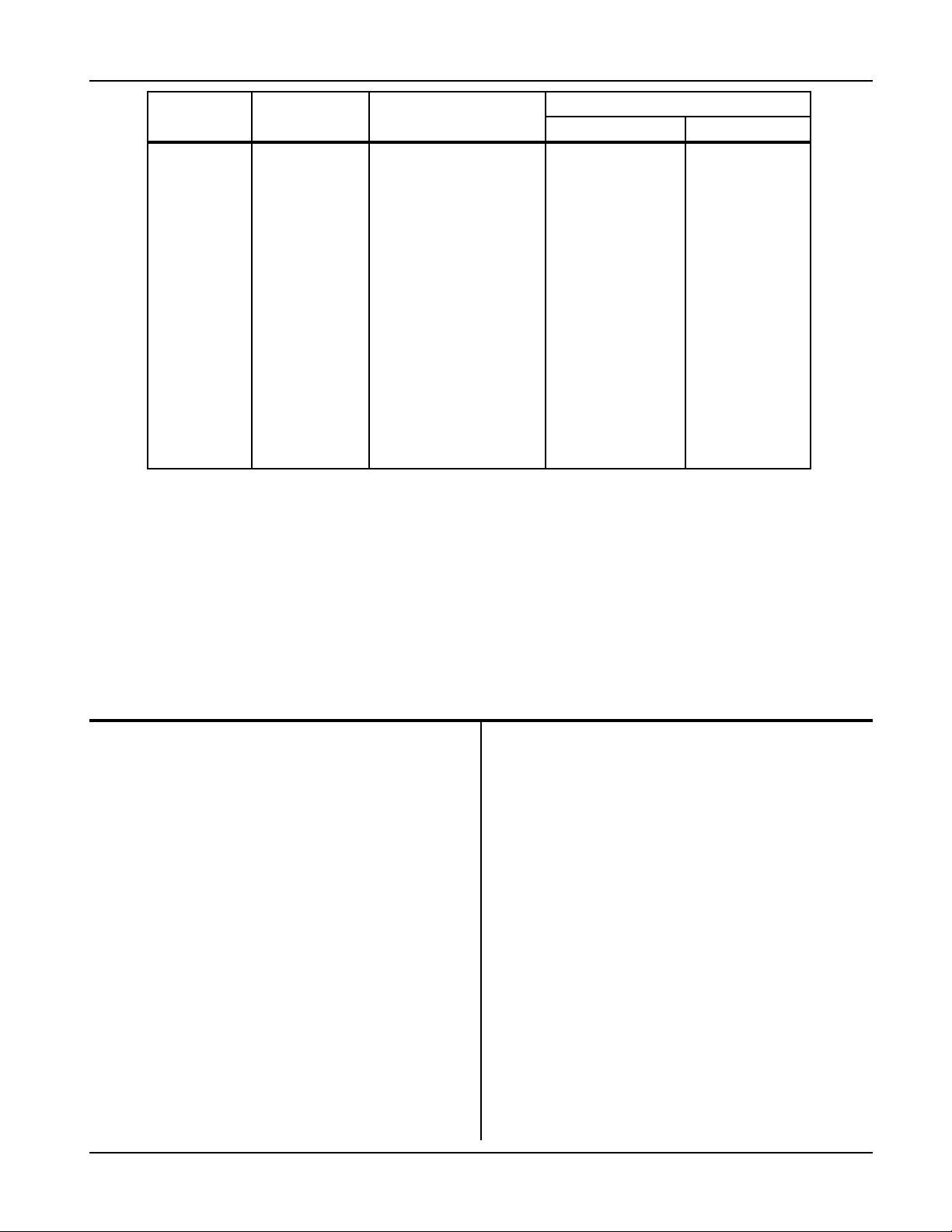
WARNING: ELECTRIC SHOCK
HAZARD – Under no circumstance
should you use a grounding
conductor with a current carrying
capacity less than the ampere
rating shown in Table 4-1.
April 26, 2007 4-1
193111-075
INSTALLATION
INSTALLATION

193111-075
INSTALLATION
4-2 Revised October 20, 2008
Table 4-1 Recommended AC Input and Branch Fusing
LINE AMPS DISCONNECT
SWITCH *
BRANCH FUSE SIZE
(AMPERES)
COPPER CABLE SIZE AWG * *
POWER GROUND
0-2.5 30A 5 No. 14 No. 14
2.6-4.5 30A 7 No. 14 No. 14
4.6-7.5 30A 10 No. 14 No. 14
7.6-12 30A 15 No. 14 No. 14
12.1-16 30A 20 No. 12 No. 12
16.1-18 30A 25 No. 10 No. 10
18.1-24 30A 30 No. 10 No. 10
24.1-32.5 60A 40 No. 8 No. 10
32.6-40 60A 50 No. 8 No. 10
40.1-45 60A 60 No. 6 No. 10
45.1-57.5 100A 80 No. 4 No. 8
57.6-78 100A 100 No. 2 No. 8
78.1-102.5 200A 125 No. 2 No. 6
102.6-135 200A 150 No. 1/0 No. 6
The above table (Table 4-1) is based on 75°C (167°F) rated conductors and 40°C (104°F) ambient temperatures.
Refer to National Electrical Code (2005) Tables 310-16 corrected to 40°C (104°F).
* For 115, 208, and 230-volt lines, use 250-volt disconnect switch.
For 440-480, 575-volt lines, use 600-volt disconnect switch.
* * Two conductors and ground conductor required for single phase.
Three conductors and ground conductor required for three phase.
Recommended minimum size of grounding conductors (based on National Electrical Code 2005 – Table 250-95).
Line Voltage Changeover Instructions
1. Determine if the charger is connected for available
line voltage. A label located near AC input terminals
is marked with the AC voltage for which the charger
is factory connected.
2. If charger is not connected correctly, check serial
nameplate to determine that charger is equipped
to be connected for available line voltage. If charger
is suitably equipped, make voltage changeover
connections by following instructions on AC input
label inside charger.
3. If charger is reconnected, check input fuse (s) ratings
with ratings specified on label and replace if
necessary.
CAUTION: INCORRECT CONNECTIONS
AND INCORRECT FUSE SIZE can damage
this equipment. Follow voltage changeover
instructions carefully.
Line Connections to Battery Charger
Follow local code requirements if different than
instructions in this manual.
1. Turn charger OFF.
2. Be sure charger is connected correctly for available
line voltage as instructed above.
3. On charger nameplate, note the AC input amperes
corresponding to the line voltage to which charger
is to be connected. Use that ampere value to select
the proper disconnect switch, fuse, and power cable
sizes from Table 4-1. A “WARNING” label inside
charger also lists fuse sizes for each line voltage
(circled fuse rating is required for internal line
voltage connections made at factory).
4. Route AC power input cable in through knockout
provided in side panel of charger cabinet. Securely
fasten cable wires to a power input terminal inside
charger. Refer to Grounding section of this manual
for proper connection of grounding conductor.
(Charger cabinet top or side panel, or both, may
have to be removed to provide access to terminal
block.)

193111-075
INSTALLATION
April 26, 2007 4-3
5. With disconnect switch (on AC input power line) in
“OPEN” or “OFF” position, connect power cable
coming from charger, to the switch. Install fuses in
switch.
Charging Cable Connectors
If connectors are already attached to charging cables,
make sure that they are attached so that positive
charger polarity will connect to positive battery terminal.
If connectors must be attached to charging cables,
follow instructions supplied with connectors.
CAUTION: Make sure connectors are
securely attached to cables (good
solder joint or well tightened set screws,
whichever is applicable). Be certain
that positive charger cable will connect
to positive battery terminal. If necessary,
trace cables into charger and use
supplied connection diagram to
determine polarity. The use of a DC
voltmeter may show polarity. Improper
connections will “blow” output fuse
and may cause other damage.
Note: If this charger is equipped with certain
optional features, the connector attaching
procedure may be modified. Refer to
OPTIONS chapter of this manual for details.
Pre-operation Checks
1. Inspect charger thoroughly for damage; loose
screws, nuts, or electrical connections.
WARNING: ELECTRICAL SHOCK
HAZARD – Before inspecting or
cleaning inside cabinet, turn OFF
and remove fuses of disconnect
switch (supplying AC power to
charger) and disconnect battery.
2. Remove all special tags that are tied to charger.
Keep tags with this manual for future reference.
Leave all precautionary and instruction labels in
place on charger. Carefully read and follow
instructions on all tags and labels. Make sure all
labels remain visible to anyone operating charger.
3. Make sure all charger cabinet panels are fastened
in place, to assure proper flow of ventilating air
through cabinet.
Pre-Operation Changes To The Factory
Control Settings
Typically few changes are required to be made if the
amp hour rating is sized to the battery and the voltage
rating is equal to or greater than the battery. However,
in some applications, some changes to the program-
mable control settings may be desirable. The most
common changes are listed below:
TIME
Factory Setting for Time is Eastern Standard.
(see Programming the EQUINOX).
NO GASSING HOURS
Factory Setting is 0 (see Programming the EQUINOX).
MAX BATTERY
Factory Setting is 150° F
TEMPERATURE
(see Programming the EQUINOX).
NOTE: It is advisable to check the day of the
week, date, month, and year for accuracy
AUTO EQUALIZE
Factory setting is ON
(see Programming the EQUINOX).
AUTO EQUALIZE TYPE
Factory setting is by Cycle
(see Programming the EQUINOX).
AUTO EQUALIZE COUNT
Factory setting is 05
(see Programming the EQUINOX).
Other functions are available for programming the
EQUINOX to meet your specific charging needs.
Programming these functions is described in the
Programming Your EQUINOX chapter of this manual.

5-1 Revised January 2, 2008
193111-075
MAINTENANCE
WARNING: ELECTRICAL SHOCK
HAZARD — Before inspecting or
cleaning inside cabinet, turn OFF
and remove fuses of disconnect
switch (supplying AC power to
charger) and disconnect battery.
Inspection And Cleaning
For uninterrupted, satisfactory service from this
charger, it's necessary to keep unit clean, dry, and
well ventilated. At least every three months, or more
often as necessary, wipe and blow out all dirt from
unit's interior components, with clean, dry air of not
over 25 psi (172 kPa) pressure. Use a hand bellows
if compressed air isn't available.
This unit is equipped with a fan, always be sure to
check for proper unrestricted operation. The fan
should operate anytime a discharged battery is con-
nected.
This unit is equipped with an input air filter located at
the bottom side of the charger. At least every 30
days, or more often if necessary, remove filter and
clean or replace it. Filter may be cleaned by washing
with hot water and detergent (such as dish soap) or
simply flush the filter in a stream of water. Air dry or
use compressed air, not over 25 psi (172 kPa).
Check and tighten all electrical connections as
necessary to eliminate unnecessary losses and to
avoid subsequent trouble from overheating or open
circuits. Check for broken wiring or damaged
Insulation on wiring.
WARNING: ELECTRICAL SHOCK
HAZARD — Failure to keep internal
parts clean and dry may allow
transformer (s) to short out,
causing secondary circuits to
carry dangerously high voltage.
Be sure to replace all charger cabinet panels after
any servicing, to assure proper flow of cooling air
through unit and to protect internal components.
WARNING: ELECTRICAL SHOCK
HAZARD — All cabinet panels must
be replaced to protect personnel from
contact with hazardous voltages.
Lubrication
None required.
Fuse Replacement
The IGBTs and silicon diodes in this charger are
protected by a “fast-clearing” type fuse.
CAUTION: The use of any other type
fuse besides the “fast-clearing” type
may cause damage to silicon diodes.
MAINTENANCE

April 26, 2007 6-1
193111-075
OPERATION
OPERATION
The operating procedure given here explains the
operation of a Prestolite EQUINOX.
NOTE: If this charger is equipped with
certain optional features, the operating
procedure may be modified. Refer to
Options chapter of this manual for details.
Options not covered in this chapter will
be described on separate “addendum”
sheets enclosed with the manual.
Preliminary
1. Make sure that charger is installed and grounded as
instructed in this manual.
2. Turn on main fused disconnect switch that supplies
AC power to charger.
3. Maintain electrolyte level in batteries to be charged,
as instructed by battery manufacturer. The volume
of electrolyte will expand during the charge.
Therefore, to avoid overfilling, do not add water
until the battery has received at least an 80%
charge. This will usually be reached at the time
gassing starts.
Normal or Daily Charge
(For batteries with ampere-hour capacity within the
range shown on charger nameplate)
1. Insure that battery size matches the charger and/or
charger setting. (Number of cells is equal to or less
than the charger nameplate rating and ampere-hour
capacity is within charger nameplate rating.) To
opportunity charge at the full output capability of the
charger, it is necessary for the battery to be
equipped with a Prestolite Power BID module.
2. Securely engage the battery and charger
connectors.
3. The charger will display READING BID and update
the progress bar. (2 to 7 seconds) as the data is
read into the charger.
4. After a short delay, the charger will turn on and the
“Charge in Progress” LED will light. The
alphanumeric display will indicate the cell size,
amp hour and phase settings for the upcoming
charge cycle. Then it will display current charging
cycle information. If not in the opportunity charging
operating mode, “Verifying Battery” may appear for
several minutes if the multi-cell mode is on.
5. The “80% Charged” LED will light when the battery
has reached the gassing point.
6. When the charge termination point is reached, the
charger will turn off and the “Charge Complete” LED
will be lit. If an equalize charge has been selected,
the “Equalize” LED will be lit.
NOTE: To disconnect battery from charger
before charge is complete, press the red
“Stop” key on the charger control panel.
NOTE: While not normally required, the
charging rate may be adjusted to compensate
for unusual ambient temperature, age of
battery, etc. Refer to items 33 through 42
in Programming Your EQUINOX chapter of
this manual.
WARNING: EXPLOSION HAZARD
- Do not connect or disconnect a
battery unless the “Charge in
Progress” LED is off; otherwise,
damage to charger, arcing and
burning of connector parts or a
battery explosion may result
(batteries produce explosive
gases). Keep sparks, flame,
and cigarettes away. Ventilate
when charging in an enclosed
area. Always shield eyes when
working near batteries.
Disconnect battery if charger is
to be turned off for prolonged
periods of time.
NOTE: To disconnect battery from charger
before charge is complete, press the
red “Stop” key on the charger control panel.

6-2 April 26, 2007
193111-075
OPERATION
Equalize or Weekend Charge
Batteries may need periodic equalizing to correct for
inequalities between cells that result from daily or
frequent cycling. An equalizing charge should be given
if any of the following conditions exist:
1. The specific gravity of any cell at the end of charge
is 20 points less than the average.
2. The on-charge voltage of any cell at the end of
charge is 20 MV less than the average.
3. The battery has been stored for 30 days.
4. A large volume of water has been added.
When the equalize mode is desired, follow the
operation outlined for a normal charge and press the
“Equalize” key to set the charge control for an
Additional 3 hours more than required for a normal
charge. The charge is complete when charge control
automatically lights the “Charge Complete” LED.
NOTE: The EQUINOX is shipped from the
factory set to the Auto Equalize by Cycle
mode, and will automatically provide an
equalize charge every 5 complete cycles.
Manual Stop
To stop any charge cycle before charge complete, press
the red “Stop” key. For maximum shift run times and
longest battery life, the charger should be allowed to
always reach charge complete.
WARNING: Do not connect a
battery to this charger if any LED
lamp is lit. Do not disconnect
a battery from this charger
while a charge is in progress.
Otherwise, damage to charger,
arcing and burning of connector
parts or a battery explosion may
result. Batteries produce
explosive gases. Keep sparks,
flame, and cigarettes away.
Ventilate when charging in an
enclosed area. Always shield
eyes when working near
batteries.
AC Power Fail
The EQUINOX Control will resume the charge where it
left off when the AC power failure occurred, virtually
unaffecting charge time.
As power is returned, if a charge cycle was in progress,
the display may show “ACFAIL RESTART”. The
charger is staggering the restart based on cycle run
times. This will prevent multiple chargers from restart-
ing all at once, minimizing peak restart power.
NOTE: If a battery is disconnected from the
charger during an AC power failure and
discharged, reconnecting it or any other
battery may result in an incomplete charge
cycle.
WARNING: ELECTRICAL
SHOCK HAZARD – Before
checking electrical
components, turn off and
remove fuses of disconnect
switch (supplying AC power
to charger) and disconnect
battery.
Abnormal Shutdowns
1. Manual Stop
If the manual stop key is pressed during the charge
cycle, the charger will shutdown. All 4 LEDS will be
flashing and the display will read “Manual Stop Fault”.
2. Back-Up Timer Shutdown
The Equinox Control has two back-up timers. The
charger will shutdown and “Backup timer” will be dis-
played if 9* hours has passed since the start of a
charge cycle and the battery has not reached gassing
voltage (80% charged), or if 4 hours has passed since
the battery has reached gassing voltage and a DV/DT
charge termination has not occurred. If the DV/DT
feature has been disabled (see Voltage Time section),
only the nine-hour back-up timer is active.
*5 hours when in Opportunity Charging mode .
3. Battery Disconnect Shutdown
If a battery is disconnected from the charger during a
charge cycle, the charger will be shut down. All LEDS
will be off.

4. Low Current Shutdown
If the charger output falls below a predetermined
level, a low current shutdown will occur. All 4 LEDS
will be flashing and the display will read “Low
Current Fault”.
5. Curve Error Shutdown
If the charger output becomes uncontrolled and falls
above or below the proper level for predetermined
period of time, the charger will shutdown. All 4
LEDS will be flashing and the display will read
“Curve Error Fault”.
6. Didt Shutdown
After the 80% charged point, if the output current
begins to rise for more than a predetermined time
period, the charger will be shutdown. All 4 LEDS
will be flashing and the display will read “Didt Fault”.
7. Low Voltage Shutdown
If a battery on charge does not reach a minimum on
charge voltage in a predetermined period of time, the
charger will be shutdown. All 4 LEDS will be flashing
and the display will read “Low Voltage Fault”.
8. High Amp Hour Returned Shutdown
If the cycle amp hours returned exceed the BID AH
setting or charger maximum AH rating by a pre-
determined amount, the charger will shutdown. All
4 LEDS will be flashing and the display will read
“High Amp Hour Fault”.
193111-075
OPERATION
April 26, 2007 6-3

Main Features
1. 20 to 50 A/100AH high rate opportunity charging
output.
2. Multi-Voltage Charging Capability
3. Multi-Ampere-Hour Charging Capability
4. Automatic or Manual Battery Temperature
Compensation
5.
15 Minute Minimum DV/DT Charge
Termination
6. 2x20 Character Alphanumeric Display
7. Four LEDs for Status Display
8. LED lamp test provided on start up
9. Manual Stop Capability
10. One touch Review of Charge Cycle
Information during charge cycle or after
charge complete
- Amp hours returned during charge cycle
- Total time on charge
- 80% point to end of charge timer
- Battery open circuit voltage
- Start current
- Start voltage (volts/cell)
- Finish current
- Finish voltage (volts/cell)
- Charge termination code
11. Review of Charge Cycle Data and
Programmed Features
12. Review of Archived Charge Cycle Data for
the Last 99 Charge cycles.
- Amp hours returned during charge cycle
- Total time on charge
- 80% point to end of charge timer
- Battery open circuit voltage*
- Start current
- Start voltage (volts/cell)
- Finish current
- Finish voltage (volts/cell)
- Charge termination code
- Equalize time
- Start time
- End time
- Truck I.D.
- Battery I.D.
- Battery I.D. start temperature
- Battery I.D. end temperature
- Cycle ampere-hours
- Cycle cell size
- Battery Type*
- Month
- Date
* NOT INCLUDED ON DATAMATE REPORT
13. Automatic or Push-to-Start Operation
14. Manual or Automatic Equalize Operation
15. Fault Lock-out or No Fault Lock-out
Operation
16. Back-up Timer Shutdowns
17. Failure Mode Diagnostics
- High Battery Reject
- Low Battery Reject
- Battery Reject
- Battery Over-temperature
- Setup Error
- Low Voltage S.D.
- Charge Curve Error
- Low Current S.D.
- Backup Timer
- Manual Stop
- Fault Lockout
- Over Maximum Amp Hour Returned S.D.
- Unbalanced Line S.D.
- DIDT S.D.
EQUINOX CONTROL FEATURES
193111-075
EQUINOX CONTROL FEATURES
Figure 7-1
7-1 April 26, 2007

193111-075
EQUINOX CONTROL FEATURES
18. One Part Number Control is User/Factory
programmable for 6-9-12-18-24 Cells
and 100-200-400-600 Amp Digital Ammeter
Note: Units that include 36 and 40 cells require
an additional part number.
19. Adjustable 8-99 Hour Refresh Charge Delay
20. Voltage Time Feature (DV/DT Disable)
21. “Cell Forming” Feature (Programmable from
0-30 Cycles)
22. Programmed Features and Archive Data
maintained for a minimum of 10 Years
23. Charge Cycle Data and Time-of-Day/Date
maintained for a minimum of 10 Years
24. 6 Programmable Start Modes
- Automatic Start (5 Second Delay)
- Push-To-Start
- Delayed Start
- Time-of-Day Start
- Time-of-Day Blockout
- Timer Mode
25. Programmable Manual Override of Start
Modes
26. User Programmable Password
27. Automatic Equalize By Number of Charger or BID
Cycles, Day of Week
28. Programmable Cool Down Time
29. Staggered Start on ACFAIL Recovery
Description of Features
Multi-Voltage Charging — The EQUINOX Charger
provides the capability to charge batteries of different
cell sizes. With the Multi-Cell Mode ON, the charger
automatically selects the proper output voltage. A 24
cell EQUINOX will safely charge 24, 18, 12, 9, and 6
cell batteries. An 18 cell EQUINOX will safely charge
18, 12, 9, and 6 cell batteries. A 40 cell EQUINOX will
safely charge 40, 36, 24, 18, and 12 cell batteries.
Fixed mode operation can be selected by programming
Multi-Cell mode to OFF. In this mode the charger will
charge only batteries of the cell size programmed into
the Fixed-Cell size function.
If the battery is equipped with Prestolite BID Module, the
Multi-Cell ON or OFF function will be overridden and the
charger will charge the battery if it is within the charger
output rating.
Multi-Ampere-Hour Charging — The EQUINOX
Charger provides the capability of charging
batteries of different cell sizes at the proper charge
rates. Fixed Mode can be selected by programming an
amp hour rating into the Fixed AH size function that is
less than the charger ampere-hour nameplate rating.
The output current will be adjusted to deliver current
at the proper rate. Attempts to program ampere-hour
sizes larger than the nameplate rating will not be
accepted by the control.
If the battery is equipped with a Prestolite BID Module,
the Fixed Ampere-Hour function will be overridden and
the charger will charge the battery at the rate
programmed into the BID Module (BID Module
programming is performed at the factory based on
information provided by the customer) if it is within the
charger output rating. If the BID and battery ampere-
hour rating are greater than the charger rating, the
charger will charge the battery at the nameplate amp
hour rating.
Multi-AH Programming Feature – The Multi-AH
Programming Feature allows the control to be
programmed to charge different voltage batteries with
the AH rates and curve types that have been
programmed for that battery voltage. When a battery
is connected, the control automatically senses the
battery voltage and sets the charge curve and charging
rates to the level that has been programmed.
If the battery is equipped with a Prestolite BID Module,
the Fixed Ampere-Hour function and Multi-AH
Programming will be overridden and the charger will
charge the battery at the rate programmed into the BID
Module (BID Module programming is performed at the
factory based on information provided by the customer)
if it is within the charger output rating. If the BID and
battery ampere-hour rating are greater than the charger
rating, the charger will charge the battery at the
nameplate amp hour rating.
Temperature Compensation — The EQUINOX
Charger is capable of modifying the output
voltage to compensate for ranges of battery electrolyte
temperatures from 32 to 150 degrees F. Because the
80% percent point is based on reaching a point on the
charge curve rather than a single voltage, it is
automatically adjusted with the output voltage.
CAUTION: Consult the battery manufacturer
for the recommended maximum battery
temperature for your battery.
When the battery is equipped with a Prestolite BID
module, the charger automatically reads the battery
temperature throughout the charge cycle and adjusts
the output voltage to match the battery temperature.
April 26, 2007 7-2

Manual adjustment of the charger output voltage to
match the temperature of the battery is performed by
programming the proper battery electrolyte
temperature into the Fixed Battery Temperature
function (BID readings automatically override the Fixed
Battery Temperature setting).
Max Battery Temperature—The EQUINOX monitors
the battery temperature throughout the charge cycle.
Programming the MAX BATT TEMP setting of the
control to the desired maximum battery temperature will
cause the charger to shut down if the battery on charge
is equipped with a BID and the temperature exceeds the
set point. It will wait until the battery temperature has
decreased to 5 degrees C below the set point before
restarting the charge cycle.
Charge Termination — The EQUINOX utilizes a
patented proportional time DV/DT technique in order to
determine the charge termination point. This technique
returns approximately 107% of the amp hours removed
from a battery (regardless of the state of discharge) and
prevents variations in the incoming AC line voltage from
affecting the amount of Energy returned to the battery.
The minimum time required for a DV/DT charge
termination on the EQUINOX Control is fifteen minutes.
The EQUINOX Control can be programmed to utilize a
voltage-time charge termination technique. If the DV/DT
charge termination is disabled, the control will terminate
the charge cycle four hours after the battery reaches
the “80% Charged” point.
Alphanumeric Display — A vacuum florescent dot
matrix 2x20 character display is standard on the
EQUINOX Control. The characters are .35 inches tall,
making the information on the digital display legible at
distances exceeding ten feet. Plain English and easy to
understand abbreviations are used to indicate charge
status output current and voltage and other functions
including; archive information, review information,
programming information, fault information, and
operating status. A blank display is utilized for AC
power fail indication.
Status Display LEDs — The “Charge In Progress” LED
(Amber) is illuminated whenever the charger is flowing
current to the battery. There are four status LEDs
provided to indicate the present operating status of the
charger and battery (see Figure 7-1). A lamp test
feature is provided. See Review of Charge Cycle
feature.
Review of Charge Cycle — When the charge cycle
is in progress or has been terminated, either by the
EQUINOX Control or the operator, the charge cycle
history can be automatically read out by pressing the
“Cycle Review” key. After displaying the information
from memory, the unit will return to the normal
(EQUINOX) display.
All status LEDs will be Illuminated during the review
of function number one, thus providing a lamp test
feature. Nine functions are displayed during a
standard review. If the charger is idle, the information
in all 58 review functions can be displayed. See the
EQUINOX Charge Cycle Review Feature section in
this chapter. A single item can be selected by
pressing the appropriate labeled key. This feature
can greatly aid in the analysis of charge data and in
situations where troubleshooting is required. See the
Troubleshooting chapter in this manual.
Automatic or Push-to-Start Operation — In the
automatic start mode, the charger will start 5-15
seconds after the battery is connected. The alphanu-
meric display will display “READING BID” and then
display upcoming cycle information. In the push-to-
start mode, the charger will not start the charge cycle
until the “Enter” key is pressed. “Ent to Start Charge”
will be displayed on battery connect when this feature
has been selected.
Manual or Automatic Equalize — An equalize
charge is a prolonged charge cycle (by 3 hours) used
to correct any inequalities of voltage and specific
gravity which may have developed between the cells
during service. EQUINOX Controls are shipped from
the factory with the automatic equalize feature
enabled. This mode of operation is indicated in the full
Review “AUTO EQ. ON” function. There are three
modes of automatic
equalize. See the Automatic Equalize section in this
chapter for further details. When the automatic
equalize feature is active, the “Equalize” key on the
front panel is disabled. When automatic equalize is
disabled, an equalize charge is requested by pressing
the “Equalize” key on the front panel of the EQUINOX
Control during countdown or after the charge cycle
has started. If this key is pressed again during the
charge cycle, the
equalize request will be canceled if the equalize period
has not begun.
Fault Lockout Operation — In the normal
operating mode (No fault lock-out), if an abnormal
shutdown occurs, disconnecting and reconnecting the
battery will clear the fault and the EQUINOX will
restart the charge cycle as programmed. If an
abnormal
shutdown occurs with the fault lock-out feature
enabled, disconnecting and reconnecting a battery will
not clear the fault condition. The alphanumeric display
will
display fault lockout, and the status LEDs will continue
to flash even with no battery connected to the charger
until the fault condition is cleared. The “Enter” key will
clear the fault if it is pressed while a battery is not
connected to the charger.
7-3 April 26, 2007
193111-075
EQUINOX CONTROL FEATURES

One Part Number Control — The standard EQUINOX
Control is user/factory programmable for 6, 9, 12, 18,
and 24 cell EQUINOXS with 100, 200, 400, and 600
amp shunts. Any combination of the above cell sizes
and current shunt sizes can be selected by DIP
switches on the P.C. board. This feature reduces the
quantity of spare parts inventory. See Figure 8-1 for
further information.
Refresh Charge Feature — A refresh charge of a
storage battery is a charge given to charged and wet
batteries which are in storage or inactive periods to
replace losses due to local action and to insure that
every cell is brought periodically to a full state of charge.
The EQUINOX Control has an adjustable 8 to 99 hour
refresh charge timer (programmed through the “Refresh
Delay” function) which starts with a normal charge
complete, either DV/DT or voltage time. If a
battery is left connected to the charger for the
programmed number of hours after a charge complete,
the control will automatically begin a refresh charge
cycle. The control will start automatically even if
programmed for time-of-day start, delayed start or push-
to-start operation. The EQUINOX will not start the
charge cycle during a time-of-day blockout period. It will
automatically request an equalize cycle if it is
programmed to equalize on that day. Charge cycle data
(Functions #1-50) is not affected by a refresh charge.
The charge termination technique for a refresh charge
will be DV/DT regardless of how the control is user
programmed, and the 0-80% back-up timer will be four
hours and fifteen minutes during a refresh charge. This
feature will insure that any battery left connected to the
charger for extended periods of time will not be
damaged due to self-discharge, and will be kept in a
fully charged state.
Finish Cell Forming Feature — The EQUINOX
Control can be programmed to provide voltage-time
charge termination and disable the low current
shutdown feature for a limited number of charge cycles.
The number of cycles programmed into the Forming
Cycles function will be forming cycles, and that number
will be decremented each time a charge complete
condition is reached. The number of forming cycles
selected can be from 0 to 30 charge cycles.
Input Kilowatt Hour Feature — The Control will
calculate the approximate input kilowatt hour usage for
each charge cycle. This feature may be helpful in
determining the cost of charging given various charging
scenarios with known electricity costs.
80% Charged Point — A standard EQUINOX Control
will light the “80% Charged” LED and enable the
charge termination routine when the battery voltage
reaches the gassing voltage and the charging has
decreased below start current. The gassing voltage is
nominally 2.40 volts/cell and is adjusted automatically
when the charger output voltage is modified to charge
batteries of different temperatures.
Data Retention — The EQUINOX Control uses 3
types of electronic memory for data retention. Real
time clock data is kept current by a non user replace-
able lithium battery in the absence of AC power. All
other program memory and charge cycle information
is resident in non-volatile flash memory or EEPROM.
The minimum data retention time should be at least
10 years.
Time-of-Day Start — The EQUINOX Control can be
programmed to delay the start of a charge cycle until a
specific time of day. Any time of day, in one minute
increments, can be used for the time-of-day start time.
When a EQUINOX is programmed for time-of-day
start, and a battery is connected to the charger, the
programmed start time will be displayed. This feature
can be used to save on energy costs, provide a
battery cool down period, or to prevent opportunity
charging.
Delayed Start — The EQUINOX Control can be
programmed to delay the start of a charge cycle for a
specific period of time. Any time period from 1 minute
to 23 hours and 59 minutes, in one minute increments,
can be used for the delayed start period. When a
EQUINOX is programmed for delayed start, and a
battery is connected to the charger, the programmed
delay time will be displayed.
The time displayed will be decremented once per
minute so that the time displayed is always the
amount of time remaining before the start of charge.
This feature can be used to save on energy costs,
provide a battery cool down period, or to prevent
opportunity charging.
193111-075
EQUINOX CONTROL FEATURES
April 26, 2007 7-4
WARNING: Enabling the Finish Cell
Forming feature will cause the charger to
continue to run for a period of time if the
battery has been disconnected before
Charge Complete or pressing the Manual
Stop key. This condition will continue
until the programmed number of cycles
have been completed. The battery
should never be disconnected while a
charge is in progress.

Time-of-Day Blockout — The EQUINOX Control can
be programmed to disable the charger during a specific
time of day. The charger will turn off at the beginning of
the blockout period, and resume the charge cycle at the
end of the blockout period. Any period of time of day, in
one minute increments, can be used for the time-of-day
blockout period. When a EQUINOX is programmed for
time-of-day blockout, and a battery is being charged
when the blockout period occurs, the programmed end
of blockout time will be displayed. This feature can be
used to save on energy costs, provide a battery cool
down period, or to prevent opportunity charging.
Manual Override of Programmed Start Modes —
A EQUINOX Control, when programmed for time-of-day
start, delayed start, or time-of-day blockout, can be
manually overridden by pressing the “Enter” pushbutton
while the start of the charge cycle is being automatically
delayed by the control. This manual override feature
can be disabled through the “Start Override” program-
ming function. The manual override feature allows the
operator to start a charge cycle immediately if a battery
is needed sooner than the programmed start time would
allow.
Automatic Equalize — The EQUINOX Control can be
programmed for 3 different types of automatic
equalize. EQUINOX Controls are shipped from the
factory programmed to automatically provide an
equalize charge to every fifth complete charger cycle.
The number of cycles between equalize requests can
be varied from 0 to 30. If the EQUINOX is programmed
to automatically provide an equalize cycle every zero
cycles, then an equalize charge cannot be requested
manually and will never be provided automatically. The
second type of automatic equalize mode is when an
equalize charge is desired on a particular day of the
week. When programmed for automatic equalize by day
of week, the EQUINOX will provide an equalize charge
to any battery which is connected to the charger on the
programmed equalize day. Additionally, any battery
which is connected the charger previous to the day of
week equalize day will be given an equalize charge
provided that it is at a charge complete status when the
EQUINOX’s clock calendar switches to the equalize
day. The automatic equalize features allow for the
consistent application of equalize charges without
constant attention by the operators. The third type of
equalize is by BID count. When programmed for this
mode, the current complete cycle count is read from the
BID at connect and compared to that of the equalize
cycle counter. An equalize will be requested when the
BID count equals the equalize cycle count programmed
into function 22.
For further information on programming and reviewing
the EQUINOX features, refer to the Programming Your
EQUINOX chapter and the Reviewing EQUINOX
Charge Data section of this chapter.
Programmable Cool Down Time — A
programmable cool down feature allows the battery to
cool down for 0 to 8 hours before the charger
signals charge complete. During the cool down
period the alphanumeric display reads “Cool Down”.
This feature allows the battery to cool down before
being returned to use and can be used to minimize the
battery maximum temperature during operation.
Start Gassing – A programmable time that effects
how long from the start of a charge cycle before the
gassing portion can begin. If the battery on charge
reaches the finish portion of the curve and the gassing
time has not elapsed, the charger current will be
allowed to go down to 1.5A/100. This minimizes any
battery gassing that may occur during an opportunity
charge cycle. Once the start gassing time is past, the
charger will go back to the standard finish current and
complete the charge cycle. This feature only works
when the charger is in Opportunity Charging mode.
Maximum Battery Temperature — The EQUINOX
Control can be programmed to interrupt the charge
cycle if the battery temperature exceeds the limit
programmed into function #57. The temperature may
be programmed from 80°F to 150°F. Once the battery
cools down past the trip temperature the charge cycle
will be resumed. The display will show “Battery
Cooling” if the charge has been interrupted and the
cooling period is taking place. A BID must be in use to
utilize this function.
User Programmable Password — You may enter a
custom 4 number password for use in keeping
programming functions protected. When the feature is
enabled (function #55), you will be prompted to enter
the password. After that, anytime the user tries to
access the programming menu, they will be prompted
for this password.
Programmable Start Rate Charging (Extended AH)
- Batteries of any AH rating less than the charger
nameplate AH rating that are equipped with a BID
module, can be configured for fast charging at start
rates up to 50 amps/100AH. This mode enables fast/
opportunity charging for a wide range of battery
ratings. To operate in this charging mode, program
the “BID battery type” (menu item 54) to curve 8, and
the “BID Start Amps” (menu item 60) to the desired
charger start rate in amps/100AH. For example, to
charge an 800AH battery at 320 amps, the “BID Start
Amps” would be programmed to 40A/100AH. Please
note that if the programmed rate exceeds the maxi-
mum rated charger amps, the charger output will be
limited to the maximum current rating.
193111-075
EQUINOX CONTROL FEATURES
7-5 April 26, 2007
Table of contents
Other Ametek Batteries Charger manuals