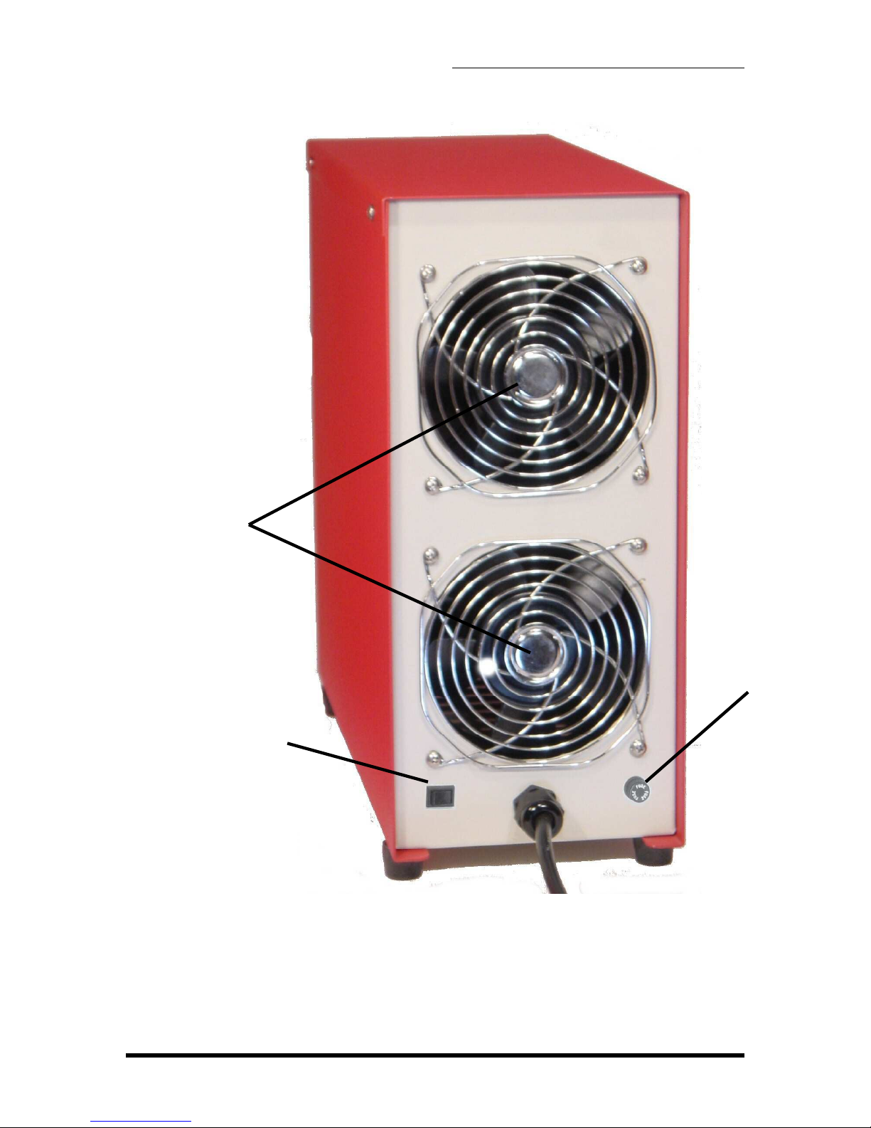
Power Products ALPHA C-20 User manual

ALPHA C-20/25
BATTERY CHARGER
OPERATING MANUAL
Power Products I c. • 27 Pamaro Way, Suite E • Novato • CA 94949
Tel: (415) 883-6300 • Fax: (415) 883-6302
www.power-products.com
www.power
-
products.com

TABLE OF CONTENTS
1. SYSTEM OVERVIEW .................................................... 3
1.1 SYSTEM OVERVIEW ............................................................. 3
1.2 DISPLAYS A D CO TROLS................................................. 3
2. INSTALLATION............................................................. 6
2.1 LI E VOLTAGE ...................................................................... 6
2.2 TERMI ALS............................................................................ 6
2.3 SPACE REQUIREME TS...................................................... 6
3. OPERATING GUIDE......................................................7
3.1 CHARGE CHARACTERISTICS.............................................. 7
3.2 CHARGI G METHODS.......................................................... 8
3.3 PREPARATIO FOR CHARGI G ......................................... 9
3.4 VERIFY E D VOLTAGE ...................................................... 10
3.5 CHARGE TIME ..................................................................... 11
4. CALIBRATION AND MAINTENANCE......................... 15
4.1 OVERVIEW OF CALIBRATIO ............................................ 15
4.2 SHU T VERIFICATIO ........................................................ 16
4.5 OPERATI G RA GES......................................................... 16
4.6 MAI TE A CE .................................................................... 17
5. TROUBLSHOOTING ................................................... 18
6. SPECIFICATIONS ....................................................... 19
APPENDIX A - BATTERY OVERVIEW............................. 20
CLASSES OF BATTERIES............................................................ 20
SECO DARY BATTERIES............................................................ 20
LEAD-ACID BATTERIES, VE TED OR SEALED (SLAB)............ 20
ICKEL-CADMIUM BATTERIES ................................................... 20
DEFI ITIO S ................................................................................. 21
WARRANTY ..................................................................... 22
CERTIFICATION OF CALIBRATION................................ 23

1. SYSTEM OVERVIEW
ALPHA C-20/25 CHARGER – OPERATI G MA UAL V1.0
Page 3
1. SYSTEM OVERVIEW
1.1 SYSTEM OVERVIEW
The Alpha C-25 Charger is a self-contained unit for charging of
rechargeable batteries. It has been designed to charge one or two batteries
of the same voltage rating simultaneously, to a combined maximum of 25
amperes. At a mere 40 lbs (18.2 kg) and 15 by 5 ¾ inches (381 by 146mm)
the C-25 takes minimal space and can easily be moved to add flexibility to
the work environment. The charger height and depth are the same as the
Power Products’ discharge tester, Beta D-50, with the same general
appearance. Therefore, two adjacent units comprise a charger/discharger,
which can service from one to three batteries simultaneously, lead-acid or
nickel cadmium.
The Alpha C-25 allows charging at both constant potential and constant
current to give flexibility in selection of charge method. The C-25 charger
has an adjustable charge current from 0 to 25 amperes. Two digital panel
meters allow viewing of charge current and voltage. They can be switched
to allow viewing of either of the two batteries being charged. A digital
electronic timer displays elapsed time and can be set to a fixed duration
charge period.
The flexibility of settings of the Alpha C-25 makes it usable for a wide variety
of batteries and voltages. The unit efficiently charges Lead Acid batteries of
12 or 24 volts, as well as ickel Cadmium batteries of a single cell to 24
volts.
1.2 DISPLAYS AND CONTROLS
The Alpha C-25 has been designed to have very simple and easy to
understand controls and displays (see figure 1-1 and 1-2).

1. SYSTEM OVERVIEW
ALPHA C-20/25 CHARGER – OPERATI G MA UAL V1.0
Page 4
Figure 1–1. Fro t view of Alpha C-25
DIGITAL CHARGE TIMER
Displays elapsed charge
time.Can be set to fixed
duration charge times
DIGITAL
VOLTMETER
Displays battery
voltage during
charge
CHARGE MODE
SELECT KNOB
Selects constant current
or constant potential
mode for 12 or 24 volt
batteries
DIGITAL AMMETER
Displays charge
current
INSTRUCTION
PANEL
AMPERE
ADJUST KNOB
Sets current
charge
ON/OFF LAMPS
Illuminate to indicate if
unit is charging (on) or
not (off)
BATTERY VIEW
SWITCH
Switches between
displaying current
and voltage for
battery one or
battery two
AC ON/OFF
SWITCH
Turns unit on
or off
DC LINE FUSE
Fuse protecting
DC line
START
BUTTON
Pressed to
start charge
DC LINE CONNECTORS
Connects for DC cable
leading to battery

1. SYSTEM OVERVIEW
ALPHA C-20/25 CHARGER – OPERATI G MA UAL V1.0
Page 5
Figure 1–2. Rear view of Alpha C-25
AC LINE FUSE
AC VOLTAGE
SELECT SWITCH
Selects mains input
voltage (115 or 230
volts)
COOLING FANS
AC MAINS CABLE

2. I STALLATIO
ALPHA C-20/25 CHARGER – OPERATI G MA UAL V1.0
Page 6
2. INSTALLATION
2.1 LINE VOLTAGE
The Alpha C-25 can operate on either 115 and 230 Volts AC. The desired
line voltage can be selected on the rear of the unit.
CAUTION: Ensure that the unit is set for the appropriate
line voltage before operation.
A. On the back of the unit locate the AC voltage select switch.
B. Set switch for appropriately marked AC voltage (115 or 230 volts).
C. For 230 VAC operation, the 115 VAC plug must be replaced with one
for 230 VAC in required configuration.
NOTE: If the plug has to be changed make sure to connect
the green AC line wire to ground.
Connect the unit to a wall outlet with a 15-20 ampere capacity. Sharing of
the line with other equipment may result in erratic operation if other
equipment draws high pulse or surge currents.
NOTE: The Alpha C-25 will maintain its operational
integrity with line fluctuation less than ± 10%.
2.2 TERMINALS
The Alpha C-25 is supplied with two DC cables. One cable has an aircraft
battery quick-disconnect connector and one has ring terminals. If the quick-
disconnect connector is removed, the ring terminals can be used to connect
to a post terminal battery, or be fitted to a different quick-disconnect
connector.
WARNING : Correct polarity must be observed.
2.3 SPACE REQUIREMENTS
The Alpha C-25 system occupies 15" x 5 ¾" (381 mm x 146 mm) of tabletop
space. Place the unit on a sturdy workbench in a well-ventilated battery
servicing area with the battery adjacent to it.

2. I STALLATIO
ALPHA C-20/25 CHARGER – OPERATI G MA UAL V1.0
Page 7
The rear of the unit has air flow for cooling. Allow at least 6" (150 mm) of
separation from the wall and adjacent equipment in order to maintain proper
air flow.
NOTE: In non air-conditioned rooms it is recommended
that circulating or extracting fans be used to aid in the
removal of heated air.
NOTE: Operation in dusty or otherwise dirty air
environments will severely reduce the cooling capacity of
the fans and can lead to premature failure.
3. OPERATING GUIDE
This section gives an overview of how to charge a battery using the Alpha C-25. Always
refer to the battery manufacturers’ maintenance manual for their recommended
charging methods and settings.
3.1 CHARGE CHARACTERISTICS
The constant current charge characteristics of a lead-acid cell with respect to cell
voltage, ampere-hours input, specific gravity and rate of gassing at constant
current can be seen in figure 3-1.

3. OPERATI G GUIDE
ALPHA C-20/25 CHARGER – OPERATI G MA UAL V1.0
Page 8
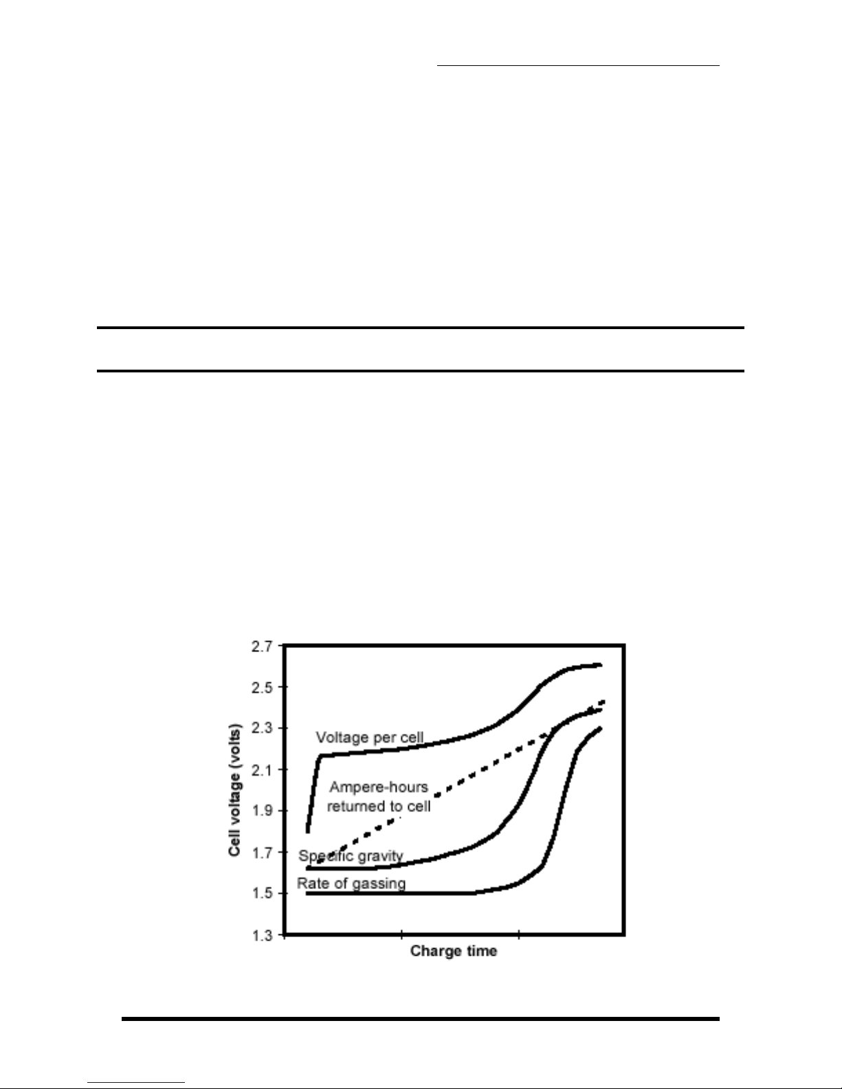
Figure 3-1. Charge characteristics of a lead-acid cell
As shown by the curve in figure 3-1 the cell voltage of a discharged battery rises
rapidly when the battery is first placed on charge. The extent of the initial rise
depends on the charging rate. As the charge continues, the voltage rises at a
slower rate and eventually levels off when a full state-of-charge is reached. It can
be seen that the specific gravity reading lags behind the rate of ampere-hour return
during most of the charging cycle. Consequently, the specific gravity is not
indicative of the available ampere-hour capacity until the cell approaches a full-
charge state.
When a battery reaches a full state-of-charge the voltage of the battery will
stabilize and remain constant or decrease. The charging should discontinue at this
stage. A minimum of 100% of previous discharge should be placed in the battery.
In general a vented battery may be charged at any rate that will not produce
excessive gassing or electrolyte temperatures above 115°F (46°C). Sealed lead-
acid batteries should never be charged in a constant-current mode with a current
greater than C
1
/10 (C
1
equals the rated capacity of the battery). During constant
current charging at a rate in excess of C
1
/10, oxygen is produced at an excessive
rate. The resulting increasing pressure will cause the cell to vent. Venting of
gasses results in a depletion of electrolyte. As the electrolyte cannot be replaced in
a sealed battery, the cell will dry out resulting in a decrease in capacity and
eventually battery failure. Therefore constant-potential charging is the
recommended charge method for sealed batteries (SLAB).
3.2 CHARGING METHODS
There are two main methods of charging a battery:
1) constant current
2) constant potential.
In what follows both methods will be described in some detail.
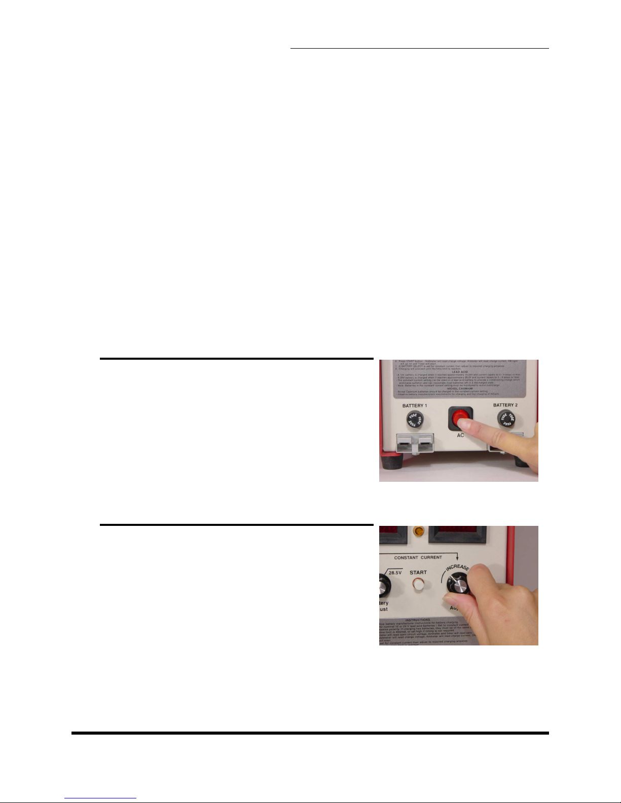
3.2.1 CONSTANT-CURRENT CHARGE METHOD
In this method the current remains at a preset level while the voltage can reach a
high level, e.g. 34-37 volts.
An advantage of the constant-current charge method is that the ampere-hour input
into the battery can be determined precisely by multiplying the charging current
with the charge time in hours. However, it is necessary to ensure that the battery is
not charged at a high rate for an excessive period of time. Such overcharging can
result in overheating, excessive gassing, and possible damage to the battery.

3. OPERATI G GUIDE
ALPHA C-20/25 CHARGER – OPERATI G MA UAL V1.0
Page 9
3.2.2 CONSTANT-POTENTIAL CHARGE METHOD
A charge source applies a fixed (constant) voltage (potential) to the battery. The
current supplied by the charge source fluctuates (rises and falls) with the battery
voltage.
There are several advantages of the constant-potential charge method. First, there
is less danger of gassing at an excessive rate. Secondly, batteries of the same
nominal voltage but with different capacities can be connected in parallel directly to
the charging source. Thirdly, batteries are charged more rapidly and with less
attention.
3.2.3 LEAD-ACID BATTERIES
With the constant-current charge method the voltage can climb to 34-37 volts.
Therefore, this method should normally not be used to charge lead-acid batteries,
especially not the sealed type (SLAB). A preferred way is to have the sealed lead-
acid battery constant-potential charged on automatic equipment at a voltage of
28.5 volts ± 0.2 volts for four hours or until the charge current drops below one
ampere.
The constant-current charge method can however be used for reconditioning
SLAB’s. The current must be set low and the timer set to 12-18 hours. The battery
should be periodically monitored for overheat during reconditioning. When the
battery begins to accept charge current, it can be switched to constant-potential
charging set to 14.25 or 28.5 volts.
3.2.4 NICKEL-CADMIUM BATTERIES
ickel-cadmium batteries may be initially charged with constant potential set to
14.25 (12 volt battery) or 28.5 (24 volt battery). After the initial charge the batteries
could be topped with a low constant-current (usually C
1
/10) charge to 1.55 volts
per cell.
The nickel-cadmium can also be completely charged in the constant-current mode.
Adjust the current to a lower rate for topping. A low constant current applied during
a long time can also be used to eliminate fading, previously called the “memory
effect”, from nickel-cadmium batteries.
3.3 PREPARATION FOR CHARGING
Before starting charging the battery, read the component maintenance manual
(CMM) or the operating and maintenance manual (OMM) for the specific battery.
Ensure that the charge time and current or voltage from the battery manufacturer
are followed.

3. OPERATI G GUIDE
ALPHA C-20/25 CHARGER – OPERATI G MA UAL V1.0
Page 10
It is recommended that a visual inspection of the battery is carried out in
conjunction with testing and charging batteries. The charging, unless otherwise
specified in the manufacturer's CMM/OMM, shall be conducted at room ambient
temperature of 70°F to 85°F (21°C to 29°C). Samples of Battery Test Records
including visual-inspection check lists can be found in Appendix B.
3.3.1 VERIFY END VOLTAGE
The end voltage (in all modes) can be verified by the following steps: 1) turn unit
power off; 2) disconnect all batteries; 3) turn charge current to max; 4) turn unit
power on; and 5) verify the end voltages on the Alpha C-25 digital voltmeter (see
also section 4.5 on modifying the operating range).
WARNING: Always turn the AC power switch off before
connecting or disconnecting a battery
NOTE: Once set, all settings are maintained and need not
be reset for duplicate charging
A. SWITCH OFF MAINS POWER
Turn off the AC on-off/reset power switch.
B. TURN DOWN CHARGE CURRENT
Repeatedly turn the Ampere Adjust knob fully
counter-clockwise to set charge current to
zero.

3. OPERATI G GUIDE
ALPHA C-20/25 CHARGER – OPERATI G MA UAL V1.0
Page 11
3.4 CHARGE TIME
3.4.1 TIMER UNIT SETTING
The Alpha C-25 has a built in timer, allowing charge time settings from 1 to 999
minutes.
3.4.2 CHARGE TIME SETTING
The charge time will be set based on the state of charge of the battery and at
which rate the battery is being charged.
A list of recommended charge times for the most common batteries can be in
Appendix C, but always refer to your battery manufacturer's maintenance manual
for the most accurate information.
C. SET TIMER
Set the timer by adjusting the thumb-dial to
the required charge time.
D. SELECT CHARGE MODE
Turn the Charge Mode Select knob to the
desired mode: 1) Constant potential 14.7
volts; 2) Constant current; or 3) Constant
potential 28.5 volts. If two batteries are to be
charged simultaneously, they will both be
charged using the selected charge mode.

3. OPERATI G GUIDE
ALPHA C-20/25 CHARGER – OPERATI G MA UAL V1.0
Page 12
E. CONNECT ONE OR TWO
BATTERIES
Connect the battery DC cable(s) to the Alpha
C25 DC Line Connectors on the front of the
unit. For single battery always use
“BATTERY 1” output. Connect the other end
of the cable(s) to the battery (or batteries).
Ensure the connectors are plugged in
completely.
F. SET BATTERY VIEW
Set the battery view switch to “VIEW BATT. 1”
G. SWITCH ON MAINS POWER
Turn on the AC on/off power switch. The
voltmeter reads the battery terminal voltage,
the ammeter reads zero, the Off lamp
illuminates and the red LED on the timer is
off.

3. OPERATI G GUIDE
ALPHA C-20/25 CHARGER – OPERATI G MA UAL V1.0
Page 13
H. PUSH START BUTTON
The timer starts. The On lamp and the red
LED on the timer illuminate. The voltmeter
displays the battery terminal voltage and the
ammeter reads zero..
I. SET CHARGE CURRENT
1. FOR CONSTANT-CURRENT
CHARGING
Turn the Ampere Adjust knob until the
desired charge current has been reached.
The charge current is displayed on the
ammeter as the current is being adjusted.
2. FOR CONSTANT-POTENTIAL
CHARGING
Turn the Ampere Adjust knob to max (fully
clockwise) or to the desired current limit. The
charge current is displayed on the ammeter
as the current is being adjusted.
J. WAIT FOR THE CHARGE TO AUTOMATICALLY
COMPLETE
During the charging of the battery the battery voltage, charge current, and
elapsed charge time are displayed.
• For the constant-current method the current remains constant while
the voltage increases during the time of charging.
• For the constant-potential method the charger’s end voltage remains
constant while the current starts at a high value and gradually
approaches zero as the battery approaches a full charge.
The actual charge voltage is determined by the battery, until the constant
voltage is reached (14.7 volts, 28.5 volts or 35 volts in constant
-
current

3. OPERATI G GUIDE
ALPHA C-20/25 CHARGER – OPERATI G MA UAL V1.0
Page 14
mode)
The test completes when the set charge time has been reached. The Off
lamp illuminates.
For the constant-current method, if a second charging is desired (topping)
repeat steps C, G, and H, with the current adjusted to a lower value.
K. UPDATE BATTERY RECORDS
Record the charge data in the battery records to ensure good maintenance
of the battery (see Appendix B).
L. SWITCH AC POWER OFF
Switch the AC on/off switch off before
removing the battery.
NOTE: If in emergency it is required to stop
charging, switch the unit to off. When
charging is restarted the timer is reset to
zero. It may be necessary to adjust the
parameters (current and time) before
resuming to charge.

4. CALIBRATIO A D MAI TE A CE
ALPHA C-20/25 CHARGER – OPERATI G MA UAL V1.0
Page 15
4. CALIBRATION AND MAINTENANCE
4.1 OVERVIEW OF CALIBRATION
The Alpha C-25 has been calibrated before shipment from the manufacturer. A
certificate of calibration with test instruments traceable to the ational Institute of
Standards and Testing in accordance with MIL-I-45208A has been issued and is
enclosed in the back of this manual. To ensure error-free operation over time,
calibration should be verified every 12 months depending on usage and changes in
surrounding environment.
4.1.1 DIGITAL PANEL METERS
There are two main indicators that can be periodically verified: 1) the voltmeter;
and 2) the ammeter (see figure 1-1 in section 1). In addition the internal shunt,
even though calibrated and certified by the shunt manufacturer, could be verified.
4.1.2 TIMER
The timer is a very accurate crystal-controlled device, not prone to error. It cannot
be re-calibrated, but unless an extremely accurate time reading is required, an
accurate analog or digital stop watch is adequate to validate its accuracy.
4.1.3 OPERATING RANGES
The Alpha C-25 gives the capabilities to modify the charge voltage in constant-
potential mode as well as the voltage limit in constant-current mode.
WARNING: Calibration should only be performed by
trained personnel. If performed incorrectly it could result in
electrical shock leading to injury or death.
The Alpha C-25 Battery Charger ow i cludes exter al test poi t jacks
for voltage a d curre t verificatio .
Voltage Verificatio – Do ot co ect C-25 to battery. Select 28.5 V
setti g. Usi g a exter al calibrated digital meter (set to DC Volt
scale), co ect to voltmeter test jacks a d verify voltage pa el meter
is withi approximately 0.3 volts.
Curre t Verificatio - Co ect C-25 to battery a d discharge
at approx. 20 Amps. Usi g a exter al calibrated digital
meter (set to millivolt scale), co ect to ammeter test jacks
a d verify pa el meter is withi approx. 0.3 Amps.

4. CALIBRATIO A D MAI TE A CE
ALPHA C-20/25 CHARGER – OPERATI G MA UAL V1.0
Page 16
4.2 SHUNT VERIFICATION
The Alpha C-25 internal shunt is calibrated and certified by the shunt
manufacturer. The shunt is a linear resistive device consisting of a heavy brass
base and heavy manganin (copper alloy) resistance. It is not necessary to calibrate
the shunt, however the shunt could be verified with the help of an external
calibrated shunt and a millivoltmeter (see figure 4-3).
EXTERNAL CALIBRATED
MILLIVOLTMETER
Figure 4-3 Circuit diagram for shu t verificatio
4.3 OPERATING RANGES
The main Alpha C-25 circuit board P/ BD50PC has factory-preset trimpots for
modifying voltages settings and limits.
4.3.1 MODIFYING VOLTAGES FOR CONSTANT-POTENTIAL MODE
The low charge voltage, factory-preset at 14.25 volts, can be modified by adjusting
the R10 trimpot on PCB BD50PC. To modify the high charge voltage, factory-
preset at 28.5 volts, adjust the R12 trimpot on the same board.
4.3.2 MODIFYING MAXIMUM VOLTAGE SETTING
To modify the maximum voltage limit in constant-current mode adjust the R11
trimpot on PCB BD50PC.

4. CALIBRATIO A D MAI TE A CE
ALPHA C-20/25 CHARGER – OPERATI G MA UAL V1.0
Page 17
4.4 MAINTENANCE
Standard electrical equipment maintenance and cleaning procedures should be
followed.
4.4.1 VENTS AND FAN
Regularly check that the rear fan vents are clean to ensure adequate cooling of the
unit. This is especially important when the unit is placed in a dusty or otherwise
dirty air environment.
4.4.2 DC BATTERY CABLES
Inspect DC battery cables and connectors periodically. Replace damaged or worn
cable.
4.4.3 REPLACEMENT OF FUSES
The Alpha C-25 is equipped with three fuses. One 20 ampere AC line fuse and two
35 ampere DC line fuses. See specification in section 6 for the specific types of
fuses required.
WARNING: Disconnect AC voltage and battery before
attempting to replace any fuses.
To replace the AC line fuse unscrew the fuse cover on the rear of the unit and
exchange the old fuse (see picture 1-2 in section 1).
To replace the DC line fuses unscrew the fuse cover just above the DC Line
Connector and exchange the old fuse (see picture 1-1 in section 1).
4.4.4 CLEANING AGENTS
Do not use acetone and other similar cleaning agents on the meters, timer or any
plastic part.

5. TROUBLESHOOTI G
ALPHA C-20/25 CHARGER – OPERATI G MA UAL V1.0
Page 18
5. TROUBLSHOOTING
Problem Possible Cause Corrective Actio
A. Unit will not
turn on
The AC power is not
connected to unit
Check AC line with voltmeter
AC line fuse is blown. May be
due to incorrect AC line
voltage setting.
Ensure correct AC line voltage
setting on back of unit. (see section
2.1)
Replace AC line fuse located on the
lower right hand side on the rear of
the unit (see section 4.6)
B. Unit turns on
but will not start
(timing)
Timer is set to zero time, or
incorrectly to seconds or low
decimal unit.
Increase the timer setting (see
section 3.4)
C. o or very low
charge current
The lead-acid battery is
sulfated and will not support a
load
Recondition or discard the battery
High resistance or open
circuit in DC cable at Elcon
connector, in the cable itself
Inspect and measure resistance in
DC cable and connector. If high or
intermittent high resistance, the
cable needs to be replaced
The lead-acid battery is
sulfated
Check all terminals. Set a low
discharge current and look for
arching or heat generation.
The nickel-cadmium battery
inter-cell connectors are loose
or contaminated causing high
resistance
Check all terminals and inter-cell
connectors. Set a low discharge
current and look for arcing or heat
generation.
D. The DC fuse(s)
blow
Reversed polarity of battery
connection
Ensure that polarity is respected on
battery connection. If connector has
been removed ensure that DC
leads are not reversed.
Defective power control
module
With AC voltage and battery
disconnected, open unit and
remove heavy leads from terminals
on black 2”x2” power module.
Check resistance between + and -
terminals with ohmmeter. If short
circuit, call Power Products
technical service.
If trouble cannot be located contact Power Products technical services at (415) 479 - 5047

6. SPECIFICATIO S
ALPHA C-20/25 CHARGER – OPERATI G MA UAL V1.0
Page 19
6. SPECIFICATIONS
AC Li e I put: 115 volts ± 10%, 50/60Hz, 13 amperes or
230 volts ± 10%, 50/60Hz, 6 amperes
(selectable on rear of unit)
Co sta t Curre t
Mode:
Capacity
Accuracy
0-25 amperes adjustable; 35 volt limit
< ± 2% from charge initiation to completion
Co sta t Pote tial
Mode
Setti g Selectable 14.25/28.5 volts; 25 ampere limit
Accuracy < ± 0.1 volts
Timer Setti g Adjustable from 0 to 999 units
U its Selectable on front of timer from 1 to 999
minutes
Accuracy < ± 0.1%
Digital
Meter Accuracy:
Voltmeter < ± 0.3 volts
Ammeter < ± 0.3 amperes
Cooli g: Fan cooled
Housi g: Aluminum chassis
Outer Dime sio s:
Height 14 in. (356 mm)
Depth 15 in. (381 mm)
Width 5 3/4 in. (146 mm)
AC Li e Cord: AWG 14 3 wire grounded 6 ft long with 115
volt 15 ampere plug. User required to change
to 230 volt plug
DC Discharge
Cable:
Two 4 ft long, terminated in ring terminals
(Aircraft Battery Connector Optional)
Weight: et 40 lbs. (18.2 kg) Shipping 45 lbs. (20.4
kg)
Fuses: AC li e fuse 20A/250V, type MDA 1 1/4 x 1/4
DC li e fuses Two 35A/32V, type AGC 1 1/4 x 1/4
Modes: 1) Constant current charging with voltage
limit; and 2) Constant voltage charging with
current limit

APPE DIX A – BATTERY OVERVIEW
ALPHA C-20/25 CHARGER – OPERATI G MA UAL V1.0
Page 20
APPENDIX
APPENDIX A - BATTERY OVERVIEW
CLASSES OF BATTERIES
Batteries can be divided into two major classes: primary and secondary. The primary
batteries are not practically reusable once its useful energy has been discharged. The
secondary battery is rechargeable. In the following only secondary batteries will be
covered.
SECONDARY BATTERIES
Secondary batteries differ from primary batteries in that they may be recharged. Some
of the materials in the cells of primary batteries are usually consumed in the process of
changing chemical energy into electrical energy. In the secondary system, the materials
are transferred from one electrode to the other as the cells discharge. The cells are
restored to their original state of charge by forcing an electric current through the cells in
a direction opposite to that of the discharge. These batteries are used in a multitude of
applications ranging from megawatt sizes in submarines to milliwatt sizes in portable
radios.
LEAD-ACID BATTERIES, VENTED OR SEALED (SLAB)
The lead-acid battery is a rechargeable system using acid electrolyte (sulfuric acid and
water). Lead-acid batteries may be vented or sealed. The advantages of lead-acid
batteries are that they have a low initial cost, require low maintenance, and their discard
cost is low. The SLAB, on a per-weight basis, provides as much power as a nickel-
cadmium battery. Lead-acid batteries shed active material from the positive plate,
proportional to the number of charge/discharge cycles. This results in diminishing
battery performance with age and loss of active material on the positive plates due to
the washing action of the gas bubbles generated during charge. The open circuit
voltage of a fully charged cell is about 2.1-2.2 volts. The discharge voltage is about 2.0
volts and varies with temperature, discharge rate, charge state, and age. The SLAB
must be charged in a constant potential mode.
The lead-acid battery is the most widely used of the secondary battery types. Major
applications include automobiles, aircraft, aircraft support equipment, and various
industrial applications.
NICKEL-CADMIUM BATTERIES
The nickel-cadmium battery is a rechargeable system using alkaline electrolyte (a 31%
aqueous solution potassium hydroxide). ickel-cadmium batteries, which may be
vented or sealed, have overcharge capability, high rate charge acceptance and nearly
Other manuals for ALPHA C-20
1
This manual suits for next models
1
Table of contents
Other Power Products Batteries Charger manuals