KEMPOWER T-Series Installation instructions

Installation & Operating manual | EN
1
| 2020-08-14
©
T-Series charging station
Installation & Operating manual - EN
T-Series
Electric vehicle charging station

Installation & Operating manual | EN
2
| 2020-08-14
©
T-Series charging station
Installation & Operating manual - EN
CONTENTS
1. Kempower T-Series................................................................................................................3
2. Equipment parts ....................................................................................................................4
3. Safety ......................................................................................................................................6
4. Installation .............................................................................................................................7
4.1. Fixed installation (optional) .....................................................................................9
5. Operation .............................................................................................................................12
6. Maintenance.........................................................................................................................14
6.1. Troubleshooting and error codes ..........................................................................15
7. Technical data ......................................................................................................................16
Prepared Status Security level
2020-08-13 JAM Approved Public
Approved Document type
2020-08-14 PKO Operating manual
Organization Document ID Rev. Lang. Pages
KEMPOWER T-series charging station manual B EN 19

Installation & Operating manual | EN
3
| 2020-08-14
©
T-Series charging station
Installation & Operating manual - EN
1. KEMPOWER T-SERIES
Kempower's T-Series DC charging trolleys are movable and modular charging solutions for commercial use.
They can be used for charging passenger cars as well as off-highway vehicles. Due to the modular design
along with replaceable power modules and charging connectors, the same charging trolley can be
customized to provide the best possible charging result according to your specific preferences and needs. T-
Series charging trolley provides 40 kW of pure charging power and allows simultaneous dual charging with
20 kW from each channel.
Features
•Movable, with wheels in the front
•Interface for fixed installation included (optional)
•Maximum output power 40 kW (or optionally 2x20 kW in simultaneous dual charging)
•Output voltage 500 V or 800 V (depending on the power module used)
•CCS Type 2, CHAdeMO and Type 2 charging connectors available
•7" touch screen with on-screen user guidance
•User authentication via RFID (Radio-Frequency Identification)
•Internet cloud connection via built-in WiFi and mobile data (3G/4G) connection
•Charge status LED indicators.
Important notes
Read the instructions through carefully. Pay particular attention to the safety instructions.
Items in the manual that require particular attention in order to minimize damage and harm are indicated
with the below symbols. Read these sections carefully and follow their instructions. T-series package – see
appendix 1
Note: Gives the user a useful piece of information.
Caution: Describes a situation that may result in damage to the equipment or system.
Warning: Describes a potentially dangerous situation. If not avoided, it will result in personal
damage or fatal injury.
DISCLAIMER
While every effort has been made to ensure that the information contained in this guide is accurate
and complete, no liability can be accepted for any errors or omissions. Kempower reserves the right
to change the specification of the product described at any time without prior notice. Do not copy,
record, reproduce or transmit the contents of this guide without prior permission from Kempower.

Installation & Operating manual | EN
4
| 2020-08-14
©
T-Series charging station
Installation & Operating manual - EN
2. EQUIPMENT PARTS
1. Charging connectors *
2. RFID reader (RFID = Radio Frequency Identification)
3. Function button
4. 7" touch screen
5. ON/OFF start switch
6. Charge level indicator **
7. Rear support
8. Front support
9. Rating plate.
* Connector types:
** Charge level indicator logic:
•LEDs are green: charging operation completed successfully
•LEDs are blue: charging operation ongoing
•LEDs are red: an error has occured.

Installation & Operating manual | EN
5
| 2020-08-14
©
T-Series charging station
Installation & Operating manual - EN
This equipment complies with IEC 61851-21-2. According to the electromagnetic compatibility
classification (EMC Class A), the equipment is not intended for use in residential locations where
the electrical power is provided by a public low-
voltage supply system. In those locations it may
be difficult to ensure the electromagnetic compatibility due to conducted and radiated
disturbances.
EQUIPMENT IDENTIFICATION
Serial number
Serial number of the device is marked on the rating plate or in another distinctive location on the device.
It is important to make correct reference to the serial number of the product when ordering spare parts
or making repairs for example.
Quick Response (QR) code
The serial number and other device-related identification information may also be saved in the form of a
QR code (or a barcode) on the device. Such code can be read by a smartphone camera or with a
dedicated code reader device providing fast access to the device-specific information.

Installation & Operating manual | EN
6
| 2020-08-14
©
T-Series charging station
Installation & Operating manual - EN
3. SAFETY
This chapter contains important information which either supplements or supersedes other instructions
related to this product. Read these instructions carefully.
Furthermore, the installation and use of the device must follow the instructions given in the international
standards regarding the installation and use of the device type in question. Always follow also your local
rules and legislation regarding the installation and use of high-voltage units.
Important notes for safe use
•Straighten any loops in the cables.
•Do not wrap the cables around the body.
•Only connect the charging device to an earthed electric network.
•Note the recommended mains fuse size.
•Do not take and use the charging device inside a container, vehicle or similar confined space.
•Ensure the cables are not squashed by heavy objects and that they are not exposed to sharp edges.
•Make sure that faulty and damaged cables and charging connectors are changed immediately as
they can be lethal and may cause electrocution or fire.
•Remember that the cable, plugs and other electric devices may be installed or replaced only by an
electrical contractor or engineer authorized to perform such operations.
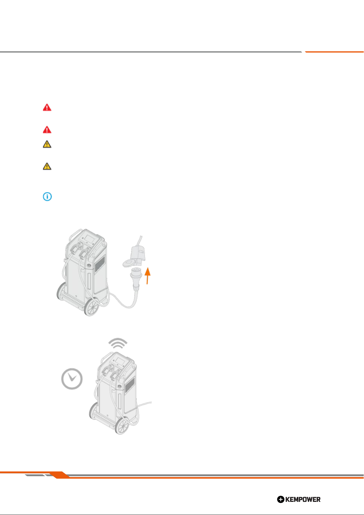
•Turn off and disconnect the charging device when it is not in use for longer periods of time.
•In case of any abnormal behavior of the equipment, such as smoke coming from the machine
during normal use, contact a Kempower service representative to arrange an inspection.
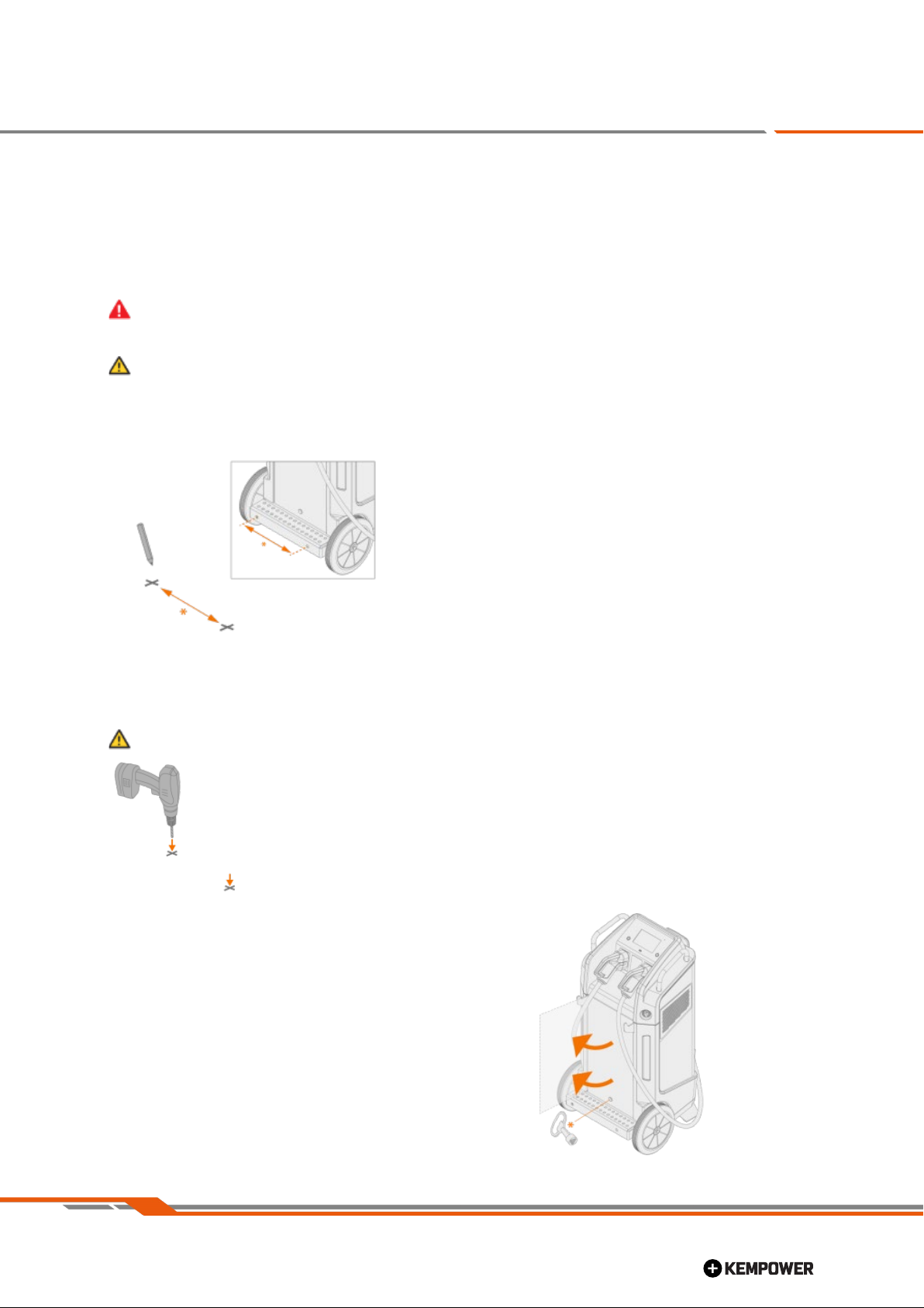
•Never pull or move the machine by the cables. Always use the handles designed for that purpose.
•Use special caution when moving and handling the equipment. The T-Series charging trolley
equipment weighs approximately 135 kg, depending on the current setup.
•The handles on the machine are not suitable for lifting.
•Try to transport the machine in an upright position, if possible. (If necessary, tilt the machine down
on its front for transportation.)
•Use the machine in an upright position only.
•Never move the device during charging.
•It is not recommended to use extension cord (additional cable) between charging trolley and the
power supply outlet. Long extension cords may block walkways and is subject to risk of electric
shock.
Environment
•Do not expose the device to high temperatures, as this may cause damage to the device.
•Protect the equipment against heavy rain and strong sunlight.
•Always store the machine in a dry and clean space.
•Protect the machine from sand and dust during use and in storage.
•The recommended operating temperature range is -30 to +40 °C.
•Make sure the airflow to and from the machine is unrestricted.
Warning: Never disconnect the charging trolley from the power supply outlet while trolley is
charging. Unit must be always switched OFF prior to disconnection.
Note: Operational safety on appendix 2

Installation & Operating manual | EN
7
| 2020-08-14
©
T-Series charging station
Installation & Operating manual - EN
4. INSTALLATION
This section describes how to take the T-Series charging trolley into use.
Use caution when moving the equipment. This equipment weighs approximately 135 kg,
depending on the current setup.
Do not lift up the T-Series charging trolley from its top handles.
Always follow your local rules and legislation regarding the use and installation of high-voltage
units.
Ensure that the location and surroundings are suitable for charging trolley operation. E.g. the
cables can be routed and/or protected in such a way that they cannot get caught between any
sharp edges.
Refer to the "Technical data" on page 16 for the power supply requirements.
1. Connect the charging trolley to the power supply outlet.
2. Wait until the trolley is ready for use. The status is indicated on the trolley display.
>
The trolley connects automatically to the mobile data network using the built-in 3G/4G/WiFi
function.

Installation & Operating manual | EN
8
| 2020-08-14
©
T-Series charging station
Installation & Operating manual - EN
Wireless mobile data network and internet connectivity rely on your local service provider's
network and its settings. For network specifications, refer to "Technical data" on page 16.
3. By the time unit is ready to use, please select from the trolley touch screen power supply source
32
A or 63 A, accordingly to the site.
4. When the unit is to be not used for longer period of time - first turn OFF from ON/OFF start switch,
wait until all lights are off then disconnect the charging trolley from the power supply outlet.

Installation & Operating manual | EN
9
| 2020-08-14
©
T-Series charging station
Installation & Operating manual - EN
4.1. Fixed installation (optional)
The T-Series charging trolley can be fixed in place by securing it with bolts to a mounting pad or other
suitable fixing surface. Fixed installation requires the removal of the wheels. Site-specific variations in the
fixing method may occur.
Use caution when moving the equipment. This equipment weighs approximately 135 kg,
depending on the current setup.
Ensure that the installation surface is suitable for drilling and bolt fixing, or that it is otherwise
prepared for the fixed installation.
1. Mark the fixing hole locations to the mounting surface.
2. Drill the fixing holes to the mounting surface. The hole depth and diameter depend on the fixing
accessory dimensions. Distance between holes is 350 mm. Unit can be installed total of 4 anchors,
distance between fixing hole rows is also 350 mm. Hole diameter on front support is 18 mm, back
support has open hole grooves, use appropriate anchor and washers.
Move the charging trolley aside when drilling.
3. Open the front maintenance hatch with the triangle key (*).

Installation & Operating manual | EN
10
| 2020-08-14
©
T-Series charging station
Installation & Operating manual - EN
4. Release the front support securing screws behind the hatch edge on both sides.
5. Flip the front support down.
6. Fix the front support securing screws behind the hatch edge on both sides.
7. Remove the wheels and start removing the axle rod.
Make sure that the trolley cannot tilt or fall forward once the wheels are removed.
At first, remove the axle rod only partially (only from the axle rod hole on the first side).

Installation & Operating manual | EN
11
| 2020-08-14
©
T-Series charging station
Installation & Operating manual - EN
8. On the first side, insert and secure a dedicated bolt and nut (delivered with the device) into the axle rod
hole.
9. Remove the axle rod fully.
10. On the second side, insert and secure a dedicated bolt and nut (delivered with the device) into the axle
rod hole.
11. Using suitable bolt plugs, washers and bolts, secure the charging trolley in place. Fixing accessory
dimensions and specifications depend on the installation surface and site conditions.

Installation & Operating manual | EN
12
| 2020-08-14
©
T-Series charging station
Installation & Operating manual - EN
5. OPERATION
This section describes how to start using the T-Series charging trolley once the installation and initial setup
are completed. For using the charging device, follow the device's on-screen instructions.
Start-up
Refer to the "Installation" on page 7section for starting up the T-Series charging trolley.
Identification (if enabled)
1. Use your RFID-enabled (RFID = Radio-frequency identification) identification card on the device.
>
On the T-Series charging trolley, the RFID reader is located just below the touch screen.
2. Once the identification is completed, continue to charging.
Charging
Ensure you have read and understood also the instructions of the vehicle to be charged.
1. Select the correct charging connector type. (Refer to "Equipment parts" on page 4for identifying
connectors.)
2. Attach the connector to the vehicle. Ensure that the charging connector is properly in place.
3. Turn on the charging function.
>
This initiates the trolley's charging process.
>
When not charging, the device will remain in standby.
4. Follow the charging device's on-screen instructions.

Installation & Operating manual | EN
13
| 2020-08-14
©
T-Series charging station
Installation & Operating manual - EN
Touch screen user interface of T-series provides information on charging session
5. When the unit is to be not used for longer period of time - first turn OFF from ON/OFF start switch, wait
until all lights are off then disconnect the charging trolley from the power supply outlet.
6.
In case of charging device malfunction or other unrecognized error, please disconnect the
charging device from the mains and contact your Kempower service workshop or Kempower sales
representative. For service contact information, refer to the Kempower website
(www.kempower.com).

Installation & Operating manual | EN
14
| 2020-08-14
©
T-Series charging station
Installation & Operating manual - EN
6. MAINTENANCE
Daily maintenance
Follow these maintenance procedures to maintain the proper functioning of the charging system:
•Check that all covers and components are intact.
•Check all the cables and connectors. Do not use them if they are damaged and contact service for
replacements.
The charging trolley can be wiped clean with a moist cloth. Do not use detergents. Also clean the ventilation
grilles and filters on the sides and in the rear of the unit.
Do not use pressure washing devices or compressed air to clean the device.
Periodic maintenance and service workshops
Only qualified service personnel is allowed to carry out periodic maintenance.
Only an authorized electrician is allowed to carry out electrical work.
Before opening or removing hatches or cover plates, disconnect the charging device from the
mains and wait for about 2 minutes before continuing.
Kempower service workshops complete the charging system maintenance according to the Kempower
service agreement.
The main aspects in the service workshop maintenance procedure are:
•Cleaning the machine, including the ventilation grilles and filters
•Maintenance of the charging tools/accessories
•Checking the connectors and switches
•Checking all electric connections
•Checking the charging device mains cable and plug
•Repairing and replacing defective components
•Test and calibration of operation and performance values when needed.
Find your closest service workshop at the Kempower website (www.kempower.com).

Installation & Operating manual | EN
15
| 2020-08-14
©
T-Series charging station
Installation & Operating manual - EN
6.1. Troubleshooting and error codes
In case of charging device malfunction or other unrecognized error, please disconnect the
charging device from the mains and contact your Kempower service workshop or Kempower
sales representative. For service contact information, refer to the Kempower website
(www.kempower.com).

Installation & Operating manual | EN
16
| 2020-08-14
©
T-Series charging station
Installation & Operating manual - EN
7. TECHNICAL DATA
Kempower T-Series
Feature
Description
Value
Input
AC power connection
3~, 380...480 V (+/-10%)
Nominal input current
63 A
Input frequency
50...60 Hz
Power factor (@ full load)
0.94
Efficiency
95% @ nominal output power
Output
Maximum output power
40 kW (or 2x20 kW in simultaneous dual charging)
Maximum output current (@ 500 V)
100 A
Maximum output current (@ 800 V)
60 A
Output voltage range with 500 V
module
200...500 V
Output voltage range with 800 V
module
300...800 V
General
Charging cable length
5 m
Charging connection type
CCS Type 2, CHAdeMO, Type 2 AC
Protection class
IP54
Operation temperature
-30 ... +40 °C
Maximum humidity
< 95% relative humidity
Cooling
Forced air
Dimensions (DxWxH), ca.
640x670x1220 mm
Weight (without cables) *
122 kg
Weight (with cables), approx. *
135 kg
User interface
ON/OFF switch, two function buttons, 7" touch screen, RFID
reader **
Network connection type
Wireless 4G mobile data connection
Wireless connection specification
4G Dongle E3372
FDD: DD800 / 900 / 1800 / 2100 / 2600
UMTS: 900 / 2100
GSM: 850 / 900 / 1800 / 1900
Standards
Electrical safety
IEC 61851-1, -23
Electromagnetic compatibility (EMC)
IEC 61851-21-2
*
Power module weight (43 kg) included.

Installation & Operating manual | EN
17
| 2020-08-14
©
T-Series charging station
Installation & Operating manual - EN
**
RFID = Radio Frequency Identification.
Single Line Drawing of Trolley DC charging station
T-series overall measures
Appendix 1

Installation & Operating manual | EN
18
| 2020-08-14
©
T-Series charging station
Installation & Operating manual - EN
Package information
T-series charging station is delivered on a palette.

Installation & Operating manual | EN
19
| 2020-08-14
©
T-Series charging station
Installation & Operating manual - EN
Appendix 2
Operational Safety
Operational Safety (Users)
It is mandatory to read this operating manual and obtain its instructions
Charging connector is mechanically locked onto vehicle during charging session
Charging voltage is not present at charging connector pins when not charging
Charging connectors control pins are shorter than charging pins, should connector be removed
from a vehicle, communication stops, and the unit stops charging
Unit has different operating lights for ready (green), charging (blue) and error (red)
For each charging session, user is authorized prior to charging (if enabled)
Device safety (charging station)
Electromechanical design is waterproof, IP classification according to IP54
Mechanical design is according to IK08 and it withstands heavy use
User interface provides selection of current according to available power supply source on T-series
Electrical safety internal over leak DC current monitoring according to IEC 61851-1, -23
Overcurrent protection MCB class C
Continuous overheating monitoring and automated power management
Power grid conditions are also monitored over and under voltages
Monitoring of the charging DC voltage; over and under voltages
Only an authorized electrician is allowed to carry out any electrical work on the charging station
Vehicle safety (all vehicle types)
Vehicle manufactures adopts standards and use high quality components to ensure that charging
and operating vehicle is safe
During charging session, vehicle management system (VMS) prevents vehicle to start and move,
notice that charging session block off some of the vehicle’s functions, refer to user manual
Vehicle’s drivetrain cables are colored in orange (high DC voltage)
If communication between vehicle and charging station is not available (modulated CCS2 or CAN-
bus), charging session is not possible
Power supply safety (electric power grid)
Electrification of the operating site must follow the instructions given in the international standards
regarding the installation and use of the device type in question. Always follow also your local rules
and legislation regarding the installation and use of high-voltage units.
Power supply source must meet the selected maximum current level
Table of contents
Other KEMPOWER Batteries Charger manuals