Raymarine Radar Scanner User guide

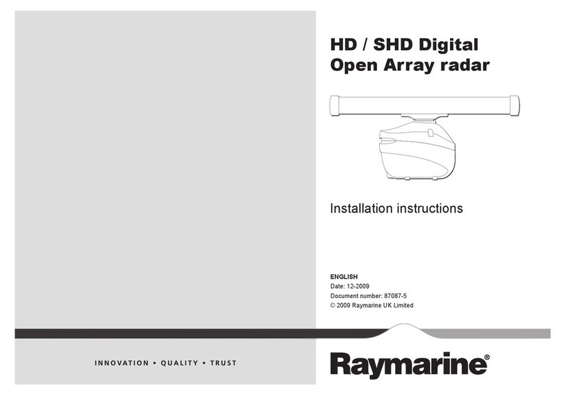
Pathfinder
Radar
Scanners
Owner’s
Handbook
Document number: 81154_4
Date: 25th October 2000
154_4.book Page -i Wednesday, October 25, 2000 3:02 PM

154_4.book Page 0 Wednesday, October 25, 2000 3:02 PM

Pathfinder Radar Scanners i
Pathfinder Radar Scanners
Owners Handbook
October 2000
SAFETY NOTICES
This radar equipment must be installed and operated in accord-
ance with the instructions contained in this manual. Failure to do
so can result in personal injury and/or navigational inaccuracies.
In particular:
1. High Voltage.The scanner unit contains high voltages. Adjust-
ments require specialised service procedures and tools only avail-
able to qualified service technicians – there are no user
serviceable parts or adjustments. The operator should never
remove the scanner unit internal covers or attempt to service the
equipment.
2. Electromagnetic Energy.The radar scanner transmits electro-
magnetic energy. It is important that the radar is turned off when-
ever personnel are required to come close to the scanner to
perform work on the scanner assembly or associated equipment.
It is recommended that the radar scanner is mounted out of range
of personnel (above head height).
Do not look directly at the antenna at close range as your eyes are
the most sensitive part of the body to electromagnetic energy.
When properly installed and operated, the use of this radar will
conform to the requirements of ANSI/IEEE C95.1-1992 Standard
for Safety Levels with Respect to Human Exposure to Radio Fre-
quency Electromagnetic Fields, 3 Hz to 300 GHz and NRPB,
Board Statement on Restrictions on Human Exposure to Static
and Time Varying Electromagnetic Fields and Radiation, Doc
NRPB, No. 5 (1993).
3. Navigation Aid. This radar unit is only an aid to navigation. Its
accuracy can be affected by many factors, including equipment
failure or defects, environmental conditions, and improper han-
dling or use. It is the user’s responsibility to exercise common
prudence and navigational judgements. This radar unit should not
be relied upon as a substitute for such prudence and judgement.
154_4.book Page i Wednesday, October 25, 2000 3:02 PM

ii Pathfinder Radar Scanners
RAYTHEON MARINE products are supported by a network of
Authorized Service Representatives. For information on Raytheon
products and services, contact either of the following:
United States Raytheon Marine Company
Recreational Products
22 Cotton Road, Suite 280
Nashua
NH 03063-4219, USA
Telephone +1 603 881 5200
Fax +1 603 864 4756
www.raymarine.com
Europe Raytheon Marine Limited
Anchorage Park
Portsmouth
Hampshire PO3 5TD
England
Telephone +44 (0)23 9269 3611
Fax +44 (0)23 9269 4642
www.raymarine.com
Copyright © Raytheon Marine Company 2000
The technical and graphical information contained in this hand-
book, to the best of our knowledge, was correct as it went to press.
However, the Raytheon policy of continuous improvement and
updating may change product specifications without prior notice.
As a result, unavoidable differences between the product and
handbook may occur from time to time, for which liability cannot
be accepted by Raytheon.
Raytheon is a registered trademark of Raytheon Company.
SeaTalk is a registered trademark of Raytheon Marine Europe
Limited.
HSB is a trademark of Raytheon Marine Company.
Pathfinder is a trademark of Raytheon Marine Company.
154_4.book Page ii Wednesday, October 25, 2000 3:02 PM

Pathfinder Radar Scanners iii
Preface
This handbook describes the following Raytheon Pathfinder radar
scanners:
2D 18" 2kWRadome Scanner
4D 24" 4kWRadome Scanner
5S 48" 4kWOpenArrayScanner
7S 72" 4kWOpenArrayScanner
9S 48" 10kW Open Array Scanner
11S 72" 10 kW Open Array Scanner
These scanner units may be connected to any HSB display unit. In
addition, the 2D and 4D radome scanner units may be connected
to SL70, or Autohelm 7" LCD display.
CAUTION:
Theopen arrayscannersmustnot beused withtheSL70or
Autohelm7"LCDDisplayUnit.Thismayresultindamagetothe
display due tothe high power requirements ofthe open array
scanner.
The handbook contains very important information on the instal-
lation and operation of your new equipment. In order to obtain the
best results in operation and performance, please read this hand-
book thoroughly.
Raytheon’s Product Support representatives or your local dealer
will be available to answer any questions you may have.
Display Software Version
For full operation of the open array scanners, the display unit
requires an appropriate software version. For new displays, the
correct software version is normally already installed in the dis-
play unit and is fully compatible with the 2D and 4D radome
scanners.
Early display units may not have the correct software for use with
open array scanners and will therefore require upgrading.
The software version can be confirmed by switching-on the dis-
play and checking the version number during the magnetron
warm-up sequence.
154_4.book Page iii Wednesday, October 25, 2000 3:02 PM

iv Pathfinder Radar Scanners
Note:If a scannerunit is not connected the version number is only
displayedfor10seconds.
Where, necessary Software Upgrade Kits are available from your
dealer, distributor or from Raytheon Marine.
We recommend that where a repeater display is fitted, both the
repeater and the master display are upgraded.
Warranty
To register your Pathfinder Radar Scanner ownership, please take
a few minutes to fill out the warranty registration card found at the
end of this handbook. It is very important that you complete the
owner information and return the card to the factory in order to
receive full warranty benefits.
The radome scanner package includes a barcode label indicating
the serial number of the unit. This label should be stuck to the
warranty registration card.
The open array scanner has two barcode labels indicating the
serial numbers of the pedestal and the antenna units. Both labels
should be stuck to the warranty registration card.
EMC Conformance
All Raytheon equipment and accessories are designed to the best
industry standards for use in the leisure marine environment.
The design and manufacture of Raytheon equipment and accesso-
ries conform to the appropriate Electromagnetic Compatibility
(EMC) standards, but correct installation is required to ensure that
performance is not compromised.
154_4.book Page iv Wednesday, October 25, 2000 3:02 PM

Contents v
Contents
Preface ................................................................................. iii
Warranty ...........................................................................iv
EMCConformance ..........................................................iv
Chapter 1: Overview ...............................................................................1
1.1 Introduction.......................................................................1
EMCinstallationguidelines .............................................2
1.2 Unpackingandinspecting thecomponents ......................4
1.3 Selecting the scanner unit site ...........................................5
1.4 Cable runs ....................................................................... 11
Radomescanner cables ...................................................13
Open array scannercables ...............................................16
Chapter 2: Installing the Scanner .......................................................21
2.1 Radomescanner ..............................................................21
Securingthe radome scannerto the mounting surface ....21
Connecting the radome scanner inter-unit cable .............22
2.2 Openarray scanner .........................................................27
Securing the pedestal tothe mounting platform ..............28
Connecting the open array scanner inter-unitcable ........29
Fitting theopen arraytothe pedestal ...............................33
2.3 Systemconnections ........................................................34
DCpower connection .....................................................34
Scannerconnection .........................................................35
Display unit connection ..................................................37
Chapter 3: Post Installation Checks and Maintenance ....................39
EMCConformance .........................................................39
3.1 SystemChecksandAlignment .......................................39
System check ..................................................................39
Set up, alignment andtiming checks ...............................39
72"openarray position alignment ..................................40
3.2 Maintenance ....................................................................41
Warnings .........................................................................41
Routine Checks ...............................................................41
Servicing and Safety .......................................................41
3.3 ProblemSolving .............................................................42
Howto Contact Raytheon(US) ......................................43
Howto Contact Raytheon(Europe) ................................44
Worldwide Support .........................................................45
154_4.book Page v Wednesday, October 25, 2000 3:02 PM

vi Pathfinder Radar Scanners
Appendix A: Specification ...........................................................47
2D18" Radome ScannerUnit ........................................47
4D24" Radome ScannerUnit ........................................48
5Sand 9S 48" OpenArray Scanner Unit ........................50
7S and 11S 72" Open Array ScannerUnit ......................53
Index .......................................................................... i
154_4.book Page vi Wednesday, October 25, 2000 3:02 PM
Chapter 1: Overview 1
Chapter 1: Overview
1.1 Introduction
This handbook provides instructions to assist you in the installation
andsetupof the followingradar scanners:
2D 18" 2kW Radome Scanner
4D 24" 4kW Radome Scanner
5S 48" 4kW Open ArrayScanner
7S 72" 4kW Open ArrayScanner
9S 48" 10 kW Open ArrayScanner
11S 72" 10 kW Open Array Scanner
Thesescannerunitsmaybeconnectedto any HSB displayunit.In
additionthe 2Dand4Dradome scannerunitsmay be connectedto
SL70,orAutohelm7" LCDdisplay.
A typical Pathfinder Radar system isillustrated below.
NMEA
SeaTalk
HSB Series Display
Scanner
12/24V Supply
12V Supply 12V Supply
Junction
Box
GPS
Distribution Panel
Compass
D4288-3
154_4.book Page 1 Wednesday, October 25, 2000 3:02 PM

2 Pathfinder Radar Scanners
CAUTION:
Donotusetheopen arrayscannerwithanSL70orAutohelm7"
LCDdisplayunit.Failureto observethis mayresult in
permanentdamage tothesedisplayunits.
The10kWopenarrayscannerrequires24Vorhigher;itwillnot
operateon 12Vsystems.
This handbookis dividedinto three chapters as follows:
ChapterOneprovidesanoverviewofthescanner installation.It
includessectionson Unpackingand Inspectingthe Components,
Selectingthe ScannerSite and a description of theCable Runs.
ChapterTwoprovidesdetailedinstructionsonhow tomount and
connecteach typeofscanner.
ChapterThreeprovides instructionson how toperform the system
checks,alignmentand adjustments. It also providesinformationon
maintenance andwhat todo if youhave problems.
EMC installation guidelines
All Raytheonequipment and accessoriesare designed tothe best
industry standards for use in the leisure marine environment.
Theirdesignandmanufactureconformstothe appropriate
Electromagnetic Compatibility (EMC)standards, but correct
installation is required to ensure that performance isnot
compromised.Although every effort hasbeen taken toensure that
they willperform under all conditions, it isimportant to understand
whatfactorscouldaffecttheoperation ofthe product.
TheguidelinesgivenheredescribetheconditionsforoptimumEMC
performance, butit is recognized that it may notbe possible to meet
all of these conditions in all situations. To ensure the best possible
conditionsfor EMC performance withintheconstraintsimposed by
any location, always ensure the maximum separation possible
between different items of electrical equipment.
For optimumEMC performance, it is recommendedthat wherever
possible:
• Raytheonequipment and cables connected to itare:
• At least 1 m(3 ft) fromany equipment transmitting orcables
carryingradiosignalse.g.VHFradios,cables and antennas.
154_4.book Page 2 Wednesday, October 25, 2000 3:02 PM

Chapter 1: Overview 3
In the case ofSSB radios, the distance should beincreased to
2 m(7 ft).
•More than2 m(7 ft) fromthe path of aradar beam. A radar
beam can normally be assumed to spread 20 degrees above
andbelowthe radiating element.
•Theequipmentissuppliedfroma separatebattery fromthatused
forengine start. Voltage dropsbelow 10 V (20V for 10 kWopen
arrayscanners)inthe power supplytoour products,and starter
motortransients,cancausetheequipmenttoreset. Thiswillnot
damage theequipment, butmay causethe loss ofsome informa-
tionandmaychangethe operatingmode.
•Raytheon specified cables are used at all times. Cutting and
rejoiningthesecablescancompromiseEMCperformanceandso
mustbe avoided unlessdoing soisdetailed inthe installation
manual.
•Ifasuppressionferriteisattachedtoacable,thisferriteshouldnot
beremoved. Ifthe ferriteneedstobe removed during installation
itmustbereassembledinthesameposition.Section2.1Installing
the Radome Scanner includes instructionsonfittinga ferrite.
The followingillustrationshows a typicalrange ofsuppression
ferrites fitted to Raytheon equipment.
Connections to Other Equipment
If your Raytheon equipmentis to be connected to other equipment
usinga cable not supplied by Raytheon, asuppression ferrite MUST
always be fitted to the cable close to the Raytheon unit.
D3548-2
154_4.book Page 3 Wednesday, October 25, 2000 3:02 PM

4 Pathfinder Radar Scanners
1.2 Unpacking and inspecting the components
Unpackyoursystemcarefully,topreventdamagetotheequipment.It
is good practice to save the carton and packingfor future use, in case
you needto return the unit for service. Check that you have all the
correctsystemcomponents.These depend onyoursystempackage,
as detailed in the following tables.
Table 1-1: Radome scanners
Item Part No. Supplied with:
Option
for:
2D 18" 2 kW Radome Scanner
2DE 18" 2 kW Radome Scanner
4D 24" 4 kW Radome Scanner
M92650
M92650E
M92652
US Version
European Version
-
-
-
-
Inter-unit cable 15 m heavy
Inter-unit cable 25 m heavy
Inter-unit cable 10 m light
Inter-unit cable 15 m light
M92668
M92669
M92692
M92720
4D
-
2D (US version)
2D (Europe version)
-
Both
-
-
Extension cable 5 m
Extension cable 10 m
M92699
M92700
-
-
Both
Both
Mast Mount 18" Scanner
Mast Mount 24" Scanner
M92722
M92698
-
-
2D
4D
Radar Interface adapter
(To fit radome to M88390 type 18"
mast mount)
M92721 -2D
Radome mounting interface plate M92731 -2D
Supplied with HSB Series Display Unit
Supplied with HSB Series Display UnitSupplied with HSB Series Display Unit
Supplied with HSB Series Display Unit
Ferrite Clamp R55007 -Both
Table 1-2: Open array scanners
Item Part No. Supplied with: Option for:
4 kW Scanner Pedestal
10 kW Scanner Pedestal
48" Open Array
72" Open Array
M92654
M92655
M92693
M92743
5S, 7S
9S, 11S
(24/32V only)
5S, 9S
7S, 11S
-
-
-
-
Inter-unit cable 15 m heavy
Inter-unit cable 25 m heavy
Cable kit: 5 m +10 m extension
(To fit open array scanner on a
radar arch)
M92728
M92705
E55017
-
-
-
5S,7S, 9S, 11S
5S, 7S, 9S, 11S
(24/32V only)
5S, 7S, 9S,11S
154_4.book Page 4 Wednesday, October 25, 2000 3:02 PM
Chapter 1: Overview 5
1.3 Selecting the scanner unit site
This section provides information that affects the possible locations
ofthe scanner, andits position relative to the display unit andto the
powersupply.
The dimensions ofthe each scanner unitare shown inthe following
diagrams.
Selectingthe best location forthe scanner unit requirescareful
considerationof the following points, to ensure reliable and trouble
free operation:
Note:Inorderto minimizepotentialinterferencetoothersystemson
boardship (EMC), it isadvisableto mount the scanner ona part of
the boat that is insulated from the ship’s battery negative. If youcan-
notdothis,andencounterproblems,youcanfitinsulatingbushesbe-
tween the scanner and its mountingbracket.
•Height:Thescannerunit shouldnormallybemounted as highas
practicalabovethe waterline,for three reasons:
•For safety reasons the scanner should be out of range of per-
sonnel,preferablyaboveheadheight.Thisavoidsmechanical
dangerand electromagnetic contact, particularly with the
eyes.
•Radaroperates at the line-of-sight, so a high mounting posi-
tiongivesbetter long range performance.
•Surrounding large objects, in the same horizontal plane, can
interferewiththeradarsignalandcauseblindareasorshadow
sectorsandfalsetargetson theradar screen (see below).
However, do not mount the scanner so high that it is affected by
thepitchingandrollingofthevessel.Inaddition,youmayneedto
lower the scanner to avoid creating a shadow sector underneath
thescanner’s beam.
Extension cable 5m
Extension cable 10m
M92699
M92700
-
-
5S, 7S, 9S, 11S
(24/32V only)
5S, 7S, 9S, 11S
Software Upgrade Kit Please contact your authorized dealer or
distributor for details
Table 1-2: Open array scanners
Item Part No. Supplied with: Option for:
154_4.book Page 5 Wednesday, October 25, 2000 3:02 PM
6 Pathfinder Radar Scanners
D3224_4
18" Radome Scanner
151.25 mm (5.95 in)
468 mm (18.4 in) dia.
Weight: 6.5 kg (14.3 lbs)
Compass safe distance: 1 m (33 in)
116.5 mm
(4.6 in)
233 mm (9.2 in)
141.5 mm (5.6 in)
227 mm (8.9 in)
302.5 mm (11.9 in)
Rear
Rear
D3228_5
Weight: 7.5 kg (16.5lbs)
Compass Safe Distance: 1m (33")
24" Radome Scanner
Rear
Rear
185.15 mm (7.3 in)
141.5 mm (5.6 in)
402 mm (15.8 in)
227 mm (8.9 in)
233 mm (9.2 in)
116.5 mm
(4.6 in)
599 mm (23.6 in) dia.
154_4.book Page 6 Wednesday, October 25, 2000 3:02 PM
Chapter 1: Overview 7
Centre of rotation Centre of rotation
48"- 1306 mm (51.4 in), 72"- 1918 mm (75.5 in)
100 mm (4 in)
427 mm (16.8 in) 296 mm (11.65 in)
406 mm (16 in)
D4572-3
Weight
Pedestal: 24 kg (53.0 lb)
48" Open Array: 6 kg (13.2 lb)
72" Open Array: 9.4 kg (20.7 lb)
Open Array Scanners
140 mm (5.5 in)
Minimum clearance height 510 mm (20.1 in)
150 mm (6 in)
Minimum clearance 630 mm (24.8 in)
70 mm
(2.75 in)
Compass Safe Distance: 1 m (33 in)
154_4.book Page 7 Wednesday, October 25, 2000 3:02 PM
8 Pathfinder Radar Scanners
•Access:Thescannerunitsiteshouldbeeasilyaccessibletoallow
maintenance to be carried out safely.
•Magneticcompass:Mount the scanner unitat least 1 maway
froma magnetic compass.
•Cablerun:The maximum length of cable between thedisplay
unitandthe scanner unit shouldnot normally exceed20m (60ft)
forradomescanners,or15 m (45 ft) for openarrayscanners. If
youneedtouse a longer cable power cablelengthsmustbe con-
sidered, refer to Section 1.4 Cable Runs to determine appropriate
lengths.
•Shadowsectorsandfalseechoes:Mountthescannerawayfrom
largestructures orequipment, such as the flybridge,largeengine
stacks,searchlights,horns,ormasts.Itisparticularlyimportantto
avoid shadow sectors near the bow. Raising or even lowering the
scanner mayhelp to reduce these effects.
In shadowareas beyond theobstruction there will be a reduction
ofthebeamintensity,althoughnotnecessarilyacompletecut-off;
there will be a blind sector if thesubtended angle is morethana
fewdegrees.
In someshadow sectors the beam intensity may not be sufficient
to obtain an echo from a very small object, even at close range,
despite thefact that a large vessel canbe detected ata much
greaterrange. Forthisreason the angular widthandrelativebear-
ing ofany shadow sector mustbe determined atinstallation.
Sometimes shadowing can be seen byincreasing the radar gain
untilnoise is present. Dark sectors indicatepossible shadowed
areas.Thisinformationshouldbepostednearthedisplayunitand
operators mustbe alert fortargets inthese blind sectors.
Itshouldalsobenotedthatwetsailscreateshadowareasandthus
sail boatoperators shouldbe aware that radarperformance may
reduce in rain.
If you mountthe scanner on a mast, echoes fromthe mast may
appear on the radar display. These can be minimized by placing
absorbingmaterial,suchasablockof wood,betweenthescanner
andmast.
•Platformrigidity/stability:Thescanner platform shouldnot
twist(causingbearingerrors)or besubjecttoexcessivevibration.
•Heat/fumes:Mount thescanneraway fromthe topof exhaust
stacks,sincethescannerandcablescanbedamagedbyexcessive
heat and the corrosiveeffectsof exhaust gases.
154_4.book Page 8 Wednesday, October 25, 2000 3:02 PM

Chapter 1: Overview 9
For open array scannersyou should also consider the following
points:
•MountingPlatform:The platformmust be mechanically secure
andcapableof supportingthemassand inertia of theopenarray
scanner. The complete unitweighs: 48" scanner -30 kg (66.2 lb);
72"scanner- 33.4kg (73.7lb).
•The sitemust be clear ofropes and moving rigging.
•Sufficient clearancemustbeallowedto fully open the openarray
pedestal for maintenance.
Mounting surface: sailboats
The scannerunit can beinstalledon a mast platform, anarch, ora
bridge structure. Make sure that theplatform surface is flat and the
scanner unitdrain hole (radome scanners) is not obstructed.
Raytheon recommendsthat radome scanner units are bestsuited for
sailboatoperation as open array systems aremore difficult to protect
fromropes andsails.
Forsailboatinstallations,Raytheonoffersa universalmastmountkit
for eachradome scanner type. This optional mount is used to fit a
radome scanner toa flat surface on amast with aminimum diameter
of60 mm(2½in). When using the mastmount kit,appropriate
hardwareshouldbeusedforthestyleandstructureofthemastaboard
the vessel.Typically, the scanner will be mounted nearthe first set of
mast spreaders. If there is any doubt concerning the appropriate type
of hardware, consultyour boat dealer orrepresentative for their
recommendations.
Depending on the type of sailboat, a radar scanner guard should be
installed if the sails could touch the scanneror platform. Without a
properradarguardthemountingplatformandtheradarscannercould
beseverelydamaged.
Mounting surface: power boats
On manysmall vessels the scanner unit can beinstalled ona mast
platform, anarch, or a bridge structure,but take careto follow the
scannersiteguidelines,particularlyregardingheight.If necessary,
constructa radar mounting platform toobtain a sufficiently high
mountingposition.Makesurethatthe platformsurfaceisflatandthe
scanner unitdrain hole (radome scanners) is not obstructed. Ensure
the platform is strong enough tosupport the maximum shock loads
likelytooccur.
154_4.book Page 9 Wednesday, October 25, 2000 3:02 PM
10 Pathfinder Radar Scanners
Setting the radiation plane
The scannerunit should be mounted so thatthe array rotates parallel
to the waterline. The radar beam is approximately 25°wide in the
verticaldirection,providinggoodtargetdetectionduringthevessel’s
pitchingand rolling.
Planing hull vessels, and some displacement hullvessels, adopt a
higher bow angle when the vessel is at itscruising speed. Inmany
cases this substantially alters and raises the radar’s main radiation
plane, and can cause poor detection of nearby targets. It may be
helpful to lower the radar beam back towards the parallel, by
shimmingtherear oftheradar, so thatthebeampointsslightly
downwards with respect to the waterline when the vessel is at rest.
Theshimsmay be made fromaluminiumplatewedges,simpleflat
washers,or anangledwoodenblock.Forthickshims,you may need
longersecuringboltsthantheM8x40boltssuppliedwiththeradome
scanner, ortheM10 studdingsuppliedwith the openarray scanners.
12.5˚
12.5˚
Waterline
Ideal Radiation Plane
D3223-2
Wedge or
washers
Using shims to lower the main beam
D3229-3
Forward
154_4.book Page 10 Wednesday, October 25, 2000 3:02 PM

Chapter 1: Overview 11
1.4 Cable runs
You need to consider the following before installing the system
cables:
•You need tofit the inter-unit cableand the power cable.
•All cables should be adequately clamped and protected from
physical damage andexposure to heat - avoidrunning cables
throughbilges or doorways, orclose to moving or hot objects.
•Acutebends mustbe avoided.
•Where a cable passes through an exposedbulkhead ordeckhead,
awatertightgland or swannecktubeshouldbe used.
•Avoidcuttingandre-joiningcables(ifnecessary,refertothenotes
below).
Youneed to run the followingcables:
CAUTION:
Donotpullthecablethroughbulkheadsusingacord attachedto
theconnector.Thiscould damagetheconnections.
•Inter-unit cable. A vinyl-coveredand shielded cable is supplied
with the radome scanner unit. The cable has a connectorplug at
one endfor connecting to the display unit or extension cable; the
otherendoftheradomescannercableisfittedwithan8-wayplug
and power cores (covered by a clear protective sleeve) for con-
necting to the scanner.
Foropenarrayscanners,variouslengthcablesareavailable.
These cables have a connectorplug at oneend for connecting to
thedisplayunitorextensioncable;theotherendispreparedready
to fit to the power and signal connectors (see Section 2.2)
•Powercable.Thescannerreceivespowerviathedisplayunit;the
powercableissuppliedwiththe displayunit. However, cable
details are provided in this section.
Rejoining Cables
You should avoid cutting and re-joining cables.If this isnecessary
youmust:
•Fit a ferrite on eachside ofthe join.The specific ferrite to use
dependsonthecabletype - contact RaytheonMarine for details.
•Take care not todamage any of the wires. Make sure that all the
wires and, in particular, the screen are reconnected correctly.
154_4.book Page 11 Wednesday, October 25, 2000 3:02 PM
12 Pathfinder Radar Scanners
If youare mounting thescanner on the mast of a sailboat, and will
need tounstep the mast, you should install asuitable junction box
inside the boat.
Ona radome scanner, the junctionbox shouldprovidean 11- or 13-
wayterminalstrip,dependingon the number ofpower cores in your
cable, with a 10 A rating. Also, you should keep the length of the un-
screened coaxial cores to less than 30 mm to maintain EMC
conformance.
Onan openarrayscanner, the junctionbox shouldprovidea 13-way
terminalstripwitha20Aratingforpowercores.Itisessentialthatall
4power cores are connectedandthat the connectionisof very low
resistance as considerable power passesthrough this connection.
Also, you should keep the lengthof the un-screened coaxial coresto
lessthan30mmto maintain EMC conformance.
Inter-unit cable
Theinter-unit cableentrance isat the rearofthe scanner unit.Ifthe
unitismountedonahollowmastthecablemayberuninsidethemast
andthen fed through the radar’s cable entrance. Make sure thatthe
cable does not chafe whereit enters and exits the mast.
Note:Route the cable from the displayup to the scanner,since this
will require thesmallest clearance hole.
CAUTION:
Thedisplayconnector ontheinter-unit cableis amouldedplug
that cannot bereplaced. DO NOTremovethis mouldedplug.
The inter-unit cable, for connecting the scanner to the display unit,
dependsonyourscannerpackage asfollows:
Theminimumbendspermittedare:
Minimumbend,lightcable 60mm (~2.5in)radius
Minimumbend,heavy cable 82mm(~3.75 in) radius
Table 1-3: Inter Unit Cables required for each Scanner Type
Scanner Package Inter-Unit Cable
2D (US) 10 m light (2 power cores)
2DE (European) 15 m light (2 power cores)
4D 15 m heavy (4 power cores)
5S, 7S (4 kW) and 9S, 11S (10 kW)
Note:
All 10 kW systems require a
minimum of 24 V.
15 m heavy or radar arch kit
(5 m + 10 m extension)
25 m heavy (24/32 V systems only)
154_4.book Page 12 Wednesday, October 25, 2000 3:02 PM
This manual suits for next models
6
Table of contents
Other Raymarine Marine Radar manuals

Raymarine
Raymarine 37STV Gen2 Programming manual

Raymarine
Raymarine Pathfinder Radar User guide

Raymarine
Raymarine STV Gen2 Owner's manual

Raymarine
Raymarine Quantum User manual

Raymarine
Raymarine Pathfinder Radar Scanners User guide

Raymarine
Raymarine RA1072HD User manual

Raymarine
Raymarine CYCLONE User manual

Raymarine
Raymarine hsb2 PLUS Series User manual

Raymarine
Raymarine VCM100 User manual

Raymarine
Raymarine Pathfinder 1200 User manual