Raymarine iTC-5 User manual

i
TC -5
Ins ta lla tion ins tructions
ENGLIS H
Docume nt numbe r: 87138-3
Da te : 03-2012
iTC-5


Trademarkandpatentsnotice
Autohelm,hsb2,RayTechNavigator,SailPilot,SeaT alk,SeaT alkNG,SeaT alkHSandSportpilotareregisteredtrademarksofRaymarine
UKLimited.RayTalk,Seahawk,Smartpilot,PathnderandRaymarineareregisteredtrademarksofRaymarineHoldingsLimited.
FLIRisaregisteredtrademarkofFLIRSystems,Inc.and/oritssubsidiaries.
Allothertrademarks,tradenames,orcompanynamesreferencedhereinareusedforidenticationonlyandarethepropertyof
theirrespectiveowners.
Thisproductisprotectedbypatents,designpatents,patentspending,ordesignpatentspending.
FairUseStatement
Youmayprintnomorethanthreecopiesofthismanualforyourownuse.Youmaynotmakeanyfurthercopiesordistributeorusethe
manualinanyotherwayincludingwithoutlimitationexploitingthemanualcommerciallyorgivingorsellingcopiestothirdparties.
Softwareupdates
Checkthewebsitewww.raymarine.comforthelatestsoftwarereleasesforyourproduct.
Producthandbooks
ThelatestversionsofallEnglishandtranslatedhandbooksareavailabletodownloadinPDFformatfromthewebsitewww.raymarine.com.
Pleasecheckthewebsitetoensureyouhavethelatesthandbooks.
Copyright©2012RaymarineUKLtd.Allrightsreserved.
ENGLISH
Documentnumber:87138-3
Date:03-2012


Contents
Chapter1Importantinformation.............................7
Safetynotices.................................................................7
Chapter2Planningtheinstallation........................9
2.1AbouttheiTC-5Converter.........................................10
2.2Handbookinformation...............................................11
2.3Systemexamples......................................................11
2.4Packcontents...........................................................15
2.5T oolsrequired...........................................................16
Chapter3Cablesandconnections.........................17
3.1Generalcablingguidance..........................................18
3.2Converterconnections...............................................19
Chapter4Locationandmounting..........................25
4.1Unitdimensions........................................................26
4.2Mounting..................................................................26
4.3Removingthefrontcover...........................................28
Chapter5Systemchecksandtroubleshoot-
ing..............................................................................29
5.1Serialnumberlocation...............................................30
5.2Typicalsystemchecks...............................................30
5.3iTC-5LEDStatusindicators.......................................31
5.4Systemdatatroubleshooting......................................33
5.5Raymarinecustomersupport.....................................34
5.6T echnicalspecication...............................................34
5.7NMEA2000sentences...............................................35
Chapter6Optionsandaccessories.......................37
6.1Spares.....................................................................38
6.2SeaT alkngcablesandaccessories..............................38
5

6iTC-5

Chapter1:Importantinformation
Safetynotices
Warning:Switchoffpowersupply
Ensurethevessel’spowersupplyisswitchedOFF
beforestartingtoinstallthisproduct.DoNOTconnect
ordisconnectequipmentwiththepowerswitchedon,
unlessinstructedinthisdocument.
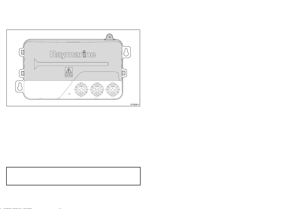
Warning:Exposedwires
Withthecoveropentheexposedtransducerwires
provideapotentialforelectricshock.
Warning:Potentialignitionsource
ThisproductisNOTapprovedforusein
hazardous/ammableatmospheres.DoNOTinstallin
ahazardous/ammableatmosphere(suchasinan
engineroomornearfueltanks).
Warning:Productinstallationand
operation
Thisproductmustbeinstalledandoperatedin
accordancewiththeinstructionsprovided.Failureto
dosocouldresultinpersonalinjury,damagetoyour
vesseland/orpoorproductperformance.
Caution:Powersupplyprotection
Wheninstallingthisproductensurethepowersource
isadequatelyprotectedbymeansofasuitably-rated
fuseorautomaticcircuitbreaker.
Caution:Serviceandmaintenance
Thisproductcontainsnouserserviceable
components.Pleasereferallmaintenanceandrepair
toauthorizedRaymarinedealers.Unauthorizedrepair
mayaffectyourwarranty.
Declarationofconformity
RaymarineLtd.declaresthatthisproductiscompliantwiththe
essentialrequirementsofEMCdirective2004/108/EC.
TheoriginalDeclarationofConformitycerticatemaybeviewedon
therelevantproductpageatwww.raymarine.com.
EMCinstallationguidelines
Raymarineequipmentandaccessoriesconformtotheappropriate
ElectromagneticCompatibility(EMC)regulations,tominimize
electromagneticinterferencebetweenequipmentandminimizethe
effectsuchinterferencecouldhaveontheperformanceofyour
system
CorrectinstallationisrequiredtoensurethatEMCperformanceis
notcompromised.
ForoptimumEMCperformancewerecommendthatwherever
possible:
•Raymarineequipmentandcablesconnectedtoitare:
–Atleast1m(3ft)fromanyequipmenttransmittingorcables
carryingradiosignalse.g.VHFradios,cablesandantennas.
Importantinformation7

InthecaseofSSBradios,thedistanceshouldbeincreased
to7ft(2m).
–Morethan2m(7ft)fromthepathofaradarbeam.Aradar
beamcannormallybeassumedtospread20degreesabove
andbelowtheradiatingelement.
•Theproductissuppliedfromaseparatebatteryfromthatused
forenginestart.Thisisimportanttopreventerraticbehavior
anddatalosswhichcanoccuriftheenginestartdoesnothave
aseparatebattery.
•Raymarinespeciedcablesareused.
•Cablesarenotcutorextended,unlessdoingsoisdetailedin
theinstallationmanual.
Note:Whereconstraintsontheinstallationpreventanyof
theaboverecommendations,alwaysensurethemaximum
possibleseparationbetweendifferentitemsofelectrical
equipment,toprovidethebestconditionsforEMCperformance
throughouttheinstallation
Productdisposal
DisposeofthisproductinaccordancewiththeWEEEDirective.
TheWasteElectricalandElectronicEquipment(WEEE)
Directiverequirestherecyclingofwasteelectricalandelectronic
equipment.WhilsttheWEEEDirectivedoesnotapplytosome
Raymarineproducts,wesupportitspolicyandaskyoutobeaware
ofhowtodisposeofthisproduct.
Technicalaccuracy
Tothebestofourknowledge,theinformationinthisdocument
wascorrectatthetimeitwasproduced.However,Raymarine
cannotacceptliabilityforanyinaccuraciesoromissionsitmay
contain.Inaddition,ourpolicyofcontinuousproductimprovement
maychangespecicationswithoutnotice.Asaresult,Raymarine
cannotacceptliabilityforanydifferencesbetweentheproduct
andthisdocument.PleasechecktheRaymarinewebsite
(www.raymarine.com)toensureyouhavethemostup-to-date
version(s)ofthedocumentationforyourproduct.
Warrantyregistration
ToregisteryourRaymarineproductownership,pleasevisit
www.raymarine.comandregisteronline.
Itisimportantthatyouregisteryourproducttoreceivefullwarranty
benets.Yourunitpackageincludesabarcodelabelindicatingthe
serialnumberoftheunit.Youwillneedthisserialnumberwhen
registeringyourproductonline.Youshouldretainthelabelforfuture
reference.
8iTC-5

2.1AbouttheiTC-5Converter
TheiTC-5converterallowsconnectionofarangeofcompatible
analoguetransducersdirectlytotheSeaTalkngnetwork.
D12026-1
Supportedtransducersanddatatypes
Thefollowingtransducertypesaresupportedbytheconverter:
•Instrumentdepth
•Instrumentspeedandseatemperature
•RaymarineWindorrotavecta
•Rudderreference
•Fluxgatecompass
Note:Ifthereisashnderinthesystemensurethatitdoes
notoperateatthesamefrequencyastheinstrumentdepth
transducer.
Supporteddatatypesareasfollows:
•AWA—Apparentwindangle
•AWS—Apparentwindspeed
•Depth
•STW—Speedthroughwater
•Logdistance
•Tripdistance
•Seatemperature
•Rudderangle
•VesselHeading
10iTC-5

2.2Handbookinformation
ThishandbookdescribeshowtoincludetheiTC-5converterwithin
aSeaTalkngnetwork,andconnectcompatibletransducers.
iTC-5handbooks
DescriptionPartnumber
InstrumenttransducerconverteriTC-5
Installationinstructions
87138
Additionalhandbooks
Youmayalsoneedtheadditionalinformationincludedinthe
SeaTalkngreferencemanual.Inparticularforassistancewith:
•constructingtheSeaT alkngnetworkandbackbone,
•connectingpower,and
•LENloadingcalculations.
DescriptionPartnumber
SeaTalkngreferencemanual81300
2.3Systemexamples
TheiTC-5convertercanbeconnectedintoaSeaTalkngnetwork,
compatibletransducerscanthenbeconnecteddirectlytothe
converter.
BasicSeaTalkngsystemexample
12 V
1
33
45
7
D12 03 3-1
44
6
8
9
2
Planningtheinstallation11

ItemDescription
1.ST70Instrumentdisplay.
2.2xi70Instrumentdisplays.
3.TerminatedSeaTalkngT-piece
connector
4.TerminatediTC-5
5.Rudderreferencetransducer
6.Depthtransducer
7.Fluxgatecompass
8.Raymarinewindtransduceror
rotavecta
9.Speedandseatemperature
transducer
12iTC-5

ExtendedSeaTalkngsystemexample
12
SMARTPILOT
Statu s
PWR /Da ta STng VHF ANT
AIS 6 50 Cla s s B Tra ns c e iver
GP S ANT
USB
S e a Ta lk
12 V
S e a Ta lkng
44
45
46
7
89
10
11
14
15
16
17 18
D12 13 1-1
19
13
12
3
Planningtheinstallation13

ItemDescription
1.ST70Instrumentdisplay
2.p70rPilotController
3.i70Instrumentdisplay
4.AIStransceiver
5.SPXcoursecomputer(supplying12VpowertoSeaTalkngnetwork.)
6.Manoverboard(MOB)
7.SeaTalkng5–wayconnector
8.Rudderreferencetransducer(connectedviaSPX)
9.Fluxgatecompass(connectedviaSPX)
10.Multi-FunctiondisplaywithbuiltinGPS
11.SeaTalktoSeaTalkngconverter
12.iTC-5
13.TerminatediTC-5
14.Trimtabs
15.Enginedata(connectedviadevicenetadaptor)
16.TerminatedSeaTalkng5–wayconnector
17.Depthtransducer
18.Speedandseatemperaturetransducer
19.Raymarinewindtransducerorrotavecta
Note:InaSPXautopilotsystemtheuxgatecompassandrudderreferencetransducermustbeconnecteddirectlytothecourse
computerandnotviatheiTC-5.
14iTC-5

Seatalkng
SeaTalkng(NextGeneration)isanenhancedprotocolforconnection
ofcompatiblemarineinstrumentsandequipment.Itreplacesthe
olderSeaT alkandSeaT alk2protocols.
SeaTalkngutilizesasinglebackbonetowhichcompatible
instrumentsconnectusingaspur.Dataandpowerarecarriedwithin
thebackbone.Devicesthathavealowdrawcanbepoweredfrom
thenetwork,althoughhighcurrentequipmentwillneedtohavea
separatepowerconnection.
SeaTalkngisaproprietaryextensiontoNMEA2000andtheproven
CANbustechnology.CompatibleNMEA2000andSeaTalk/
SeaTalk2devicescanalsobeconnectedusingtheappropriate
interfacesoradaptorcablesasrequired.
2.4Packcontents
TheiTC-5converterpackcomeswiththefollowingitems:
123
D12132-2
4
ItemDescription
1.iTC-5
2.Fixingscrewsx2
3.Documentpackincludes:
•Installationinstructions
•Warrantyregistrationcard
•MultilingualCD
4.400mmSeaTalkngspurcable(A06038)
Planningtheinstallation15

2.5Toolsrequired
Toolsrequiredforinstallation
12
3
D12 08 7-1
ItemDescription
1.PowerDrill
2.Pozidrivescrewdriver
3.3.2mm(1/8”)drillbit
16iTC-5

3.1Generalcablingguidance
Cabletypesandlength
Itisimportanttousecablesoftheappropriatetypeandlength
•Unlessotherwisestateduseonlystandardcablesofthecorrect
type,suppliedbyRaymarine.
•Ensurethatanynon-Raymarinecablesareofthecorrectquality
andgauge.Forexample,longerpowercablerunsmayrequire
largerwiregaugestominimizevoltagedropalongtherun.
Routingcables
Cablesmustberoutedcorrectly,tomaximizeperformanceand
prolongcablelife.
•DoNOTbendcablesexcessively.Whereverpossible,ensurea
minimumbenddiameterof200mm(8in)/minimumbendradius
of100mm(4in).
100 mm (4 in)
200 mm (8 in)
•Protectallcablesfromphysicaldamageandexposuretoheat.
Usetrunkingorconduitwherepossible.DoNOTruncables
throughbilgesordoorways,orclosetomovingorhotobjects.
•Securecablesinplaceusingtie-wrapsorlacingtwine.Coilany
extracableandtieitoutoftheway.
•Whereacablepassesthroughanexposedbulkheadordeckhead,
useasuitablewatertightfeed-through.
•DoNOTruncablesneartoenginesoruorescentlights.
Alwaysroutedatacablesasfarawayaspossiblefrom:
•otherequipmentandcables,
•highcurrentcarryingacanddcpowerlines,
•antennae.
Strainrelief
Ensureadequatestrainreliefisprovided.Protectconnectorsfrom
strainandensuretheywillnotpulloutunderextremeseaconditions.
Circuitisolation
Appropriatecircuitisolationisrequiredforinstallationsusingboth
ACandDCcurrent:
•Alwaysuseisolatingtransformersoraseparatepower-inverter
torunPC’s,processors,displaysandothersensitiveelectronic
instrumentsordevices.
•AlwaysuseanisolatingtransformerwithWeatherFAXaudio
cables.
•Alwaysuseanisolatedpowersupplywhenusinga3rdparty
audioamplier.
•AlwaysuseanRS232/NMEAconverterwithopticalisolationon
thesignallines.
•AlwaysmakesurethatPC’sorothersensitiveelectronicdevices
haveadedicatedpowercircuit.
Cableshielding
Ensurethatalldatacablesareproperlyshieldedthatthecable
shieldingisintact(e.g.hasn’tbeenscrapedoffbybeingsqueezed
throughatightarea).
18iTC-5

3.2Converterconnections
TheconverterconnectsinlineaspartoftheSeaT alkngbackbone.It
providesconnectionstoenabletransducerstobeinstalledontothe
SeaTalkngnetwork.
SPEED/TEMP
WIND
COMPASS
RUDDER
DEPTH
ROTA
VANE
D12029-1
3
5
2
4
678
1
ItemDescription
1.Red—Speedandseatemperature
transducerconnection
2.Orange—Windtransducerand
rotavectaconnection
3.Yellow—Fluxgatecompass
connection
4.Green—Rudderreferencetransducer
connection
5.Blue—Depthtransducerconnection
6.SeaTalkngbackboneconnection
7.SeaTalkngspurconnection
8.SeaTalkngbackboneconnection
SeaTalkngconnections
TheiTC-5converterhas2xbackboneconnectorsand1xspur
connector.
SeaTalkngbackboneconnectors
Thebackboneconnectorsenabletheconvertertobeconnectedin
lineaspartoftheSeaT alkngbackbone.
SeaTalkngspurconnector
ThespurconnectorenablesconnectionofanotherSeaTalkng
device,orconnectiontoasuitable12Vdcpowersupply.
Cablesandconnections19

1
2
D12 03 4-2
ConnectingSeaTalkngcables
1.Rotatethelockingcollaronthebackoftheunittothe
UNLOCKEDposition.
2.Ensurethespurcableendconnectoriscorrectlyoriented.
3.Fullyinsertthecableconnector.
4.Rotatelockingcollarclockwise(2clicks)untilitsnapsintothe
LOCKEDposition.
Transducerconnections
TheiTC-5allowsconnectionof5transducersontoyourSeaTalkng
network.
Speedandseatemperaturetransducerconnections
345
D12036-1
SPEED/TEMP
WIND
COMPASS
RUDDER
DEPTH
ROTA
VANE 21
ItemCablecolorSignalname
1.RedSpeedV+
2.ScreenSpeed0V(shield)
3.GreenSpeed(signal)
20iTC-5
Table of contents
Other Raymarine Media Converter manuals