Raymarine M81120 User manual

Distributed by
Any reference to Raytheon or
RTN in this manual should be
interpreted as Raymarine.
The names Raytheon and RTN
are owned by the
Raytheon Company.
All manuals and user guides at all-guides.com
all-guides.com

Hydraulic Pump
Installation Guide
Drives covered:
M81120 Type 1 Hydraulic Pump 12 V
M81119 Type 1 Hydraulic Pump 24 V
M81121 Type 2 Hydraulic Pump 12 V
M81123 Type 2 Hydraulic Pump 24 V
M81122 Type 3 Hydraulic Pump 12 V
M81124 Type 3 Hydraulic Pump 24 V
Document number: 81178-3
March 2001
All manuals and user guides at all-guides.com

2 Hydraulic Pump - Installation Guide
Important information
Safety notices
WARNING: Product installation
Thisequipmentmustbeinstalledandoperated inaccordance
withtheinstructionscontainedinthishandbook.Failuretodoso
couldresultinpoorproductperformance, personalinjuryand/
ordamage toyourboat.
Because correctperformance of the boat’ssteering is critical for
safety,weSTRONGLYRECOMMENDthatanAuthorized
RaymarineServiceRepresentativefits thisproduct.
WARNING: Navigation aid
Althoughwehavedesignedthisproducttobeaccurateand
reliable, many factorscanaffect itsperformance.Asaresult,it
shouldonlybeusedasanaidto navigationandshouldnever
replacecommonsenseandnavigationaljudgement.Always
maintainapermanentwatchsoyoucanrespondtosituationsas
theydevelop.
EMC conformance
All Raymarine equipment and accessoriesare designed to thebest
industry standards for use in the recreational marine environment.
The design and manufacture of Raymarine equipmentand
accessories conformto the appropriate Electromagnetic
Compatibility(EMC)standards,butcorrectinstallationisrequiredto
ensure that performance isnot compromised.
Handbook information
To the best of our knowledge, the informationin this handbook was
correct when it went to press. However, Raymarine cannot accept
liabilityforanyinaccuraciesoromissionsitmaycontain.Inaddition,
ourpolicy ofcontinuousproductimprovementmay change
specifications without notice.Asa result, Raymarinecannotaccept
liabilityfor any differences between the product andthe handbook.
©RaymarineLtd 2001.
All manuals and user guides at all-guides.com

Hydraulic Pump - Installation Guide 3
Introduction
Product description
Welcometotheinstallationguideforthe Raymarinehydraulicpump
(alsoknownasthe Raymarinereversinghydraulic pump).
This product is intended to operatethe boat’s steering mechanism as
partof aRaymarineautopilotsystem. Itis primarilydesignedforuse
on boats with an existing hydraulic steering system. Alternatively,
you can use this pump on a boat with mechanical steering in
conjunctionwith a secondary steeringram.
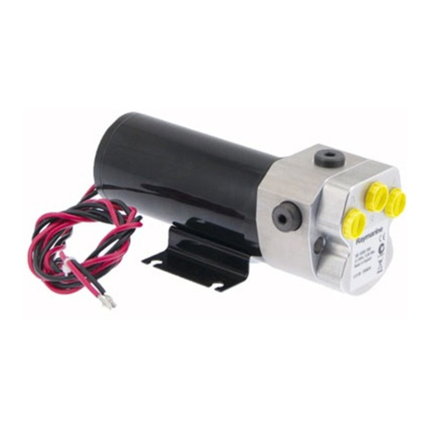
The hydraulic pump contains a precisiongear pumpand a check
valve driven by a servo motor.
Figure 1: Main parts of a typical hydraulic pump
Contents
Thisguide contains:
1Product specifications page 4
2Installation instructions page 5
3Maintenance information page 17
Mounting foot
D5175-1
Reservoir port
Ram ports
Check valve
Gear pump
Motor
All manuals and user guides at all-guides.com

4 Hydraulic Pump - Installation Guide
Specifications
Pump specifications
Pump dimensions
Figure 2: Type 1 (12 V) and Type 2 pump dimensions
Table 1: Pump specifications
Performance
(at nominal voltage)
Type 1 (T1)
M81120 (12 V)
M81119 (24 V)
Type 2 (T2)
M81121 (12 V)
M81123 (24 V)
Type 3 (T3)
M81122 (12 V)
M81124 (24 V)
Ram compatibility single or double ended
Ram capacity
(min-max)
80-230 cc
(4.9-14 in3)
230-350 cc
(14-21 in3)
350-500 cc
(21-30.5 in3)
Maximum stall
pressure (at 12 V)
50 bar
(750 psi)
100 bar
(1450 psi)
80 bar
(1160 psi)
Peak flow rate
(no load)
1000 cc/min
(67 in3/min)
2000 cc/min
(122 in3/min)
2900 cc/min
(175 in3/min)
Other information (applies to Types 1, 2 and 3)
protected for use in engine compartments
CE approvals - conforms to:
89/336/EC (EMC), EN60945:1997
94/25/EC (RCD), EN28846:1993
175 mm (6.9 in)
90 mm (3.54 in)
105 mm (4.13 in)
D5174-1
All ports are 1/4 inch BSP (parallel threaded)
Type 1 (12 V) and Type 2 pumps
two holes to accept 6 mm (0.25 in) bolts
All manuals and user guides at all-guides.com

Hydraulic Pump - Installation Guide 5
Figure 3: Type 3 pump dimensions
Installation instructions
Parts required
To install this drive you will need:
•Partssupplied:
•hydraulicpump
•ifrequired:1/4inBSPto1/4in NPTadaptors (x3)
•Additional parts:
•suitable hydraulicpipes, hydraulic fluid,T-pieces, pipe
fittingsand thread-sealingcompound (seepage 8)
•suitable securing bolts andlock washers/lock nuts (see
page 8)
•suitable cable and electrical connectors for the drive motor
andclutch(see page 13)
Note:Makesureyouhaveobtainedtheseadditionalpartsbeforeyou
startinstallation.
117 mm (4.62 in)
103 mm (4.07 in)
D5173-1
235 mm (9.25 in)
Type 3 pump
All ports are 1/4 inch BSP (parallel threaded)
holes to accept 6 mm (0.25 in) bolts
All manuals and user guides at all-guides.com
all-guides.com

6 Hydraulic Pump - Installation Guide
Installation steps
WARNING: Electrical safety
Make sure you have switched off the power supply beforeyou
start installingthis product.
Follow these steps toinstall yourhydraulic pump:
Ï
Ï
Ï
Ï
1. EMC installation guidelines
All Raymarine equipment and accessoriesare designed to thebest
industry standards for use in the recreational marine environment.
Theirdesign andmanufacture conformsto the appropriate
Electromagnetic Compatibility(EMC)standards,but correct
installation is required to ensure that performance is not
compromised.Althoughevery efforthas been takento ensure that
they willperform underall conditions, itis important to understand
whatfactorscould affecttheoperationof theproduct.
Theguidelinesgivenhere describethe conditionsforoptimumEMC
performance, butit is recognized that itmay not be possible to meet
all of these conditions in all situations. To ensure the best possible
conditionsforEMC performance withinthe constraintsimposed by
any location, always ensure the maximumseparation possible
between different items of electrical equipment.
1Consult the EMC installation guidelines. page 6
2Mount the pump. page 8
3Connect to the hydraulic steering system. page 8
4Connect to the course computer. page 13
5Complete the post-installation checks. page 15
All manuals and user guides at all-guides.com

Hydraulic Pump - Installation Guide 7
For optimumEMC performance, it is recommended that wherever
possible:
•Raymarine equipment andcables connected to it are:
•Atleast 3ft(1 m)from anyequipment transmittingor cables
carryingradio signalse.g. VHFradios,cablesand antennas.
In the case ofSSB radios, the distance should be increased to
7ft(2m).
•More than7 ft (2m) fromthe path ofa radar beam.A radar
beam can normally be assumed to spread 20 degrees above
andbelow theradiating element.
•Theequipmentissuppliedfrom a separatebatteryfrom thatused
forengine start.Voltage dropsbelow10 V,andstartermotor
transients,cancausetheequipmenttoreset.Thiswillnotdamage
theequipment, butmay causethe lossof someinformationand
maychangetheoperating mode.
•Raymarine specified cablesare used. Cutting andrejoining these
cables can compromiseEMC performance and mustbe avoided
unless doing so is detailed in the installation manual.
•Ifasuppressionferriteisattachedtoacable,thisferriteshouldnot
beremoved. Iftheferriteneedstoberemovedduringinstallation
it must be reassembled in the same position.
Suppression ferrites
Figure 4showstypicalcablesuppressionferritesused with
Raymarine equipment. Always use theferrites supplied by
Raymarine.
Figure 4: Typical Suppression Ferrites
D3548-2
All manuals and user guides at all-guides.com

8 Hydraulic Pump - Installation Guide
Connections to other equipment
If your Raymarine equipment is to be connected to other equipment
usingacablenotsuppliedbyRaymarine,asuppressionferriteMUST
always beattached tothe cable near tothe Raymarine unit.
2. Pump mounting
Mount thehydraulicpump:
•onasubstantialmembertoavoidvibrationthatcoulddamagethe
hydraulicpipes
•onasuitablehorizontalsurface,clear ofsprayandpossiblewater
immersion
•levelor abovethehydraulic steeringramtopreventaircollecting
in the ram
•as close to the ramas possible
Note:Secure the pump using M6 (1/4inch)bolts,locknutsand lock
washers.
3. Hydraulic connections
CAUTION:
Beforeyouconnecttheautopilotpumptoyourhydraulicsystem
westronglyrecommendthatyouconsultthesteeringgear
manufacturer.
General guidelines
CAUTION:
Absolute cleanlinessisessentialwhen working with hydraulic
systems. Even the smallest particle of dirt could preventthe
steeringsystemcheckvalvesfromworkingproperly.
•All pipes used to fit the pump should match, orexceed, the
specification ofthe existing steeringsystempipes. Contactthe
steeringsystemmanufacturer if youneedmore information.
•Use flexible pipe to connect the pump to the boat’s steering
system- thisavoids strain onthe pipes.
•Allports ontheautopilot pump are1/4in BSP parallel threaded. If
youneed toconvertto 1/4inNPT, use the threeBSP to NPT
adaptors(supplied).
All manuals and user guides at all-guides.com

Hydraulic Pump - Installation Guide 9
•Trytokeephydraulicfluidlosstoaminimumwheninstallingthe
pump. This will reduce the time and effort required to bleed the
systemof trappedair afterinstallation:
•non-pressurized systems: temporarily fit a non-venting plug
to the helm reservoir vent to minimize fluid loss
•pressurizedsystems:
WARNING:
Beforedisconnectinganypipesonpressurizedsystems,you
MUST release the pressureat the reservoir byfollowing the
manufacturer’sinstructions.
•Follow the manufacturer’sinstructionsifyoufitany T-pieces.
•All hydraulic pipes should slopeupwards towardsthe reservoir.
•A set of bleed valves near the steering ram,fitted at the highest
point, willallow anyairto escape upwards.
CAUTION:
DonotusePTFEtapeonhydraulicpipeconnections.Ifnecessary
usea pipe-sealingcompoundtoensurealeakproof joint.
CAUTION:
Beforerunningthepumpforthefirsttime,makesurethesystem
contains sufficienthydraulicfluid.Youwilldamagethepumpif
youletitrunwhen ‘dry’.
Check valves
Forsingle-steeringpositionboats:
•Consultthe steeringgear manufacturer todeterminewhetherthe
helm pump is fitted with reversing check valves:
•without check valves, the autopilot pump will drive the helm
pump(sometimesreferredtoas‘motoringthewheel’)instead
ofmoving thesteeringram
•Ifthe boat has asingle helm pump system withoutcheck valves,
you must incorporate adouble pilot check valve (part number
M81166) as shown in Figure 5.
•A double pilotcheck valve mayalsobe necessary onlong tubing
runs- otherwisetubingexpansion maycause poorautopilot
performance. Install the checkvalve as shown in Figure 5.
Note:Iftheboathastwosteeringpositions,itwillalreadyhavecheck
valvesinstalledsothe twowheels canoperate independently.
All manuals and user guides at all-guides.com

10 Hydraulic Pump - Installation Guide
Hydraulic steering systems
There are three basictypes of hydraulic steering systems:
•twolinesystems
•two linepressurizedsystems
•threelinesystems
Onthefollowingpages wedescribetypicalconnectionpointsforthe
autopilotpumponeach ofthese systems.For allofthesystemsyou
will needto connect a thirdhydraulic pipe (as shown) between the
autopilot pump and the helm pump or system reservoir.
Two line systems
Figure 5showsatypical twolinesteeringsystem. Hydraulicfluid
flows into the ram in either direction, depending on the direction the
helm pumprotates. Connectthe autopilot pump to the steering
systemas showninFigure 5.
Figure 5: Autopilot pump location for two line systems
D5163-1
Helm
pump
Autopilot
pump
Steering ram
Ram pipes
Reservoir pipe
Check valve (if required)
All manuals and user guides at all-guides.com
all-guides.com

Hydraulic Pump - Installation Guide 11
Two line pressurized systems
Two line pressurized systems havean external pressurized reservoir.
Thisreduces the possibility ofintroducing air into the system and
reducesany steering ‘sponginess’causedbypipeexpansion.
Connect the autopilot pump to the steering system as shown in
Figure 6.
Note:Refer to the manufacturer’s instructions for de-pressurizing
andre-pressurizingthesystem.
Figure 6: Autopilot pump location for two line pressurized systems
D5162-1
Helm
pump
Autopilot
pump
Steering ram
Ram pipes
Reservoir pipe
Pressurized reservoir
All manuals and user guides at all-guides.com

12 Hydraulic Pump - Installation Guide
Three line systems
Inathreelinesystem,thehydraulicfluidflows inonlyonedirection:
•out of the helm pump to the ram
•returning from the other side ofthe ram to the reservoir via a
commonreturn line
The system will include acheck valve blockto direct all returned
fluid from the ram back to the reservoir.
Connect the autopilot pump to thesteering system as shownin
Figure 7.
Figure 7: Autopilot pump location for three line systems
D5161-1
Helm
pump
Autopilot
pump
Steering ram
Ram pipes
Reservoir
pipe
Check valve
All manuals and user guides at all-guides.com

Hydraulic Pump - Installation Guide 13
4. Connecting to the course computer
WARNING: Electrical safety
Makesurethepowersupplyisswitchedoffbeforeyoumakeany
electricalconnections.
Thehydraulicpumphaselectricalconnectionsforitsmotor:aredand
ablack cable.
Note:To meet currentEMC legislation, you must NOTuntwistthe
pumpcables,and youmustNOTremove thesuppressionferrite.
Followthesestepstoconnectthepumpmotortothecoursecomputer:
1. Measure the distanceof cable runfrom the pump tothe course
computer,thenuse Table 2 to identify the appropriate cable sizes.
2. Join these cables to the ones onthe pump using appropriate
electricalconnectorsorjunctionboxesatthecorrectpowerrating.
3. Routethecablesbacktothecoursecomputer,takingintoaccount
the EMC installation guidelines (page 6).
4. ConnectthecablesfromthepumptotheMOTOR terminalsonthe
coursecomputer (see Figure 8): at this stage you can connect
eithermotorcabletoeitherterminal.You will check these
connections after installing therest of the autopilotsystem.
Note:Ifinstalling the pump on aboatwith mechanicalsteering,you
needtoconnect abypassvalve tothe CLUTCH terminals
(seepage 14).
Figure 8: Course computer connections
D5171-1
lk CLUTCH MOTORPOWER
+–+–12
Type 100/300 course computer
MOTORPOWER
+– AB
OFF
SWITCH SOLENOID
–
CLUTCH
+–
Type 150/400 course computer
–
All manuals and user guides at all-guides.com

14 Hydraulic Pump - Installation Guide
Mechanical steering systems
Ifyouarefittingthepumptoaboatwithmechanicalsteeringyouwill
need to connect it to asecondary steering ram, along with a solenoid-
operated bypass valve. This bypassvalve allows youto switch
between autopilot course control and manual steering.
To fit to a mechanical steering system:
•Usesuitablehydraulicpipestoconnectthepumptothesecondary
steeringram and asuitable reservoir.
•Install the solenoid-operated bypass valve (part number:
M81167)acrossthesepipes (asshown inFigure 9).
•Connect the bypass valve to the CLUTCH terminals on the course
computer using at least 1.5 mm2(16AWG)coppercable.
Table 2: Recommended cable sizes
Cable length
(pump to course computer)
Cable gauge
(AWG)
Copper area
(mm2)
Type 1 drive (12 V and 24 V)
up to 3 m (10 ft)
up to 5 m (16 ft)
up to 7 m (23 ft)
up to 10 m (32 ft)
up to 16 m (52 ft)
14
12
10
8
6
2.5
4
6
10
16
Type 2 drive 12 V
up to 5 m (16 ft)
up to 7 m (23 ft)
up to 16 m (52 ft)
10
8
6
6
10
16
Type 2 drive 24 V
up to 3 m (10 ft)
up to 5 m (16 ft)
up to 10 m (32 ft)
up to 16 m (52 ft)
12
10
8
6
4
6
10
16
Type 3 drive 12 V
up to 5 m (16 ft)
up to 7 m (23 ft)
up to 16 m (52 ft)
8
6
4
10
16
25
Type 3 drive 24 V
up to 5 m (16 ft)
up to 7 m (23 ft)
up to 16 m (52 ft)
10
8
6
6
10
16
All manuals and user guides at all-guides.com

Hydraulic Pump - Installation Guide 15
Note:Followthemanufacturer’sinstructionsformountingthe
hydraulicramandreservoir.
Figure 9: Connecting to a secondary steering ram
5. Post-installation check
WARNING:
Keepclearofmovingsteering systems atalltimes.Protect
movingpartsfromaccessduringnormaluse.
Check the following points after installing the pump:
1. Isthe pumpinstalledasclose tothe steeringram aspossible?
2. Is the pumpsecured toa substantial structure on the boat?
3. Haveyouconnectedareservoirpipebetweenthehelmpumpand
autopilotpump?
4. Haveyoufittedcheckvalveswhere appropriate?
5. Arethe hydraulicpipesmade of asuitableflexiblematerial (i.e.
rubberor nylon)with a suitable pressurerating?
6. Are power cables correctly routed and securely connected to the
coursecomputer?
Youhavenowfinishedinstallingthepump.Afterinstallingtherestof
the autopilot youmust bleed all air from the system (see below).
Note:When you have installed the entire autopilot system, you will
alsoneedtocompleteanautopilotsteeringcheck.Refertothecontrol
unit handbook for moredetails.
D5172-2
Bypass valve
Secondary steering ram
Manual steering system
Autopilot pump
connect to CLUTCH
on course computer
connect to MOTOR
on course computer
All manuals and user guides at all-guides.com
all-guides.com

16 Hydraulic Pump - Installation Guide
Bleeding the system
Bleeding the hydraulic system correctly is one ofthe most important
stepswheninstalling the autopilothydraulic pump. If there isany air
inthesystemthesteeringwillfeelspongy,particularlywhenyouturn
the wheel to hardover.
CAUTION:
Anyairinthe hydraulicsystemwillgreatlyreducethe
performance of the autopilot andthe overallsteering system.
Inaddition tothe manufacturer’s instructions forbleeding the
steeringsystem,follow thesestepsto bleedthe autopilot pumpwhen
you haveinstalled andset upthe rest of the autopilot system:
1. With the system in auto mode, pressthe -10 button ten times:
•the autopilot pump will try to drive the rudder to port
•counter this rudder movementby turning the helm to
starboard to keep the rudderstationary
•youwillbeabletofeelanyairinthehelmpump:anyairinthis
side ofthe pumpwill riseto the helm pumpand exhaustinto
thereservoir
•continue until all of the air is out ofthis sideof the pump
2. Clear anyair on the other side of the pump:
•press the +10 buttonten times
•the autopilot will try to drive the rudder to starboard
•counter the rudder movement by turning the helm to port
•continue until all of the air is out ofthis sideof the pump
3. Repeatinboth directionsuntilboth sidesofthe helppumpare
totally free of air.
Note:Monitor the reservoir atall timesand top upwith the
manufacturer’srecommendedhydraulicfluid asrequired.
CAUTION:
Afterinstallationandbleeding, leave thesystemfor24 hours
thencheckforany airinthesystemor leaks atthejointsand
aroundthepump.
All manuals and user guides at all-guides.com

Hydraulic Pump - Installation Guide 17
Maintenance
Onaregular basis:
•check that all connections and mountings are secure
•checkpipesandcablesfor any signs ofwear ordamage
•checkpipesandjointsfor anyleaks
EMC servicing and safety guidelines
•Raymarine equipment should be serviced onlyby authorized
Raymarine service technicians. Theywill ensure that service
procedures andreplacement parts used will not affect
performance. There are no user serviceable parts in any
Raymarine product.
•Some products generate high voltages: never handle thecables/
connectors when power is being supplied to theequipment.
•When poweredup, all electrical equipment produces
electromagnetic fields. These cancause adjacent pieces of
electrical equipment to interact with one another, with a
consequent adverse effect on operation. In order to minimize
these effects and enable youto get the bestpossible performance
from your Raymarine equipment, guidelines are given in the
installationinstructions,to enableyou toensure minimum
interaction betweendifferentitemsofequipment, i.e. ensure
optimum Electromagnetic Compatibility (EMC).
•AlwaysreportEMC-relatedproblemstoyournearestRaymarine
dealer.Weusesuchinformationtoimproveourqualitystandards.
•In someinstallations, itmay notbe possible to prevent the
equipment frombeing affected by external influences.In general
this will notdamage the equipmentbut it can leadto spurious
resetting action, or momentarily may result in faulty operation.
Product support
Raymarine products are supported by aworldwide networkof
distributors and Authorized Service Representatives. Ifyou
encounteranydifficulties withthisproduct, pleasecontact either
your national distributor, oryour servicerepresentative, orthe
RaymarineTechnicalServicesCallCenter.Refertothebackcover
or the WorldwideDistributorList for contactdetails.
All manuals and user guides at all-guides.com

18 Hydraulic Pump - Installation Guide
Raymarine Ltd
Anchorage Park
Portsmouth, Hampshire
England PO3 5TD
Telephone +44 (0)23 9269 3611
Fax +44 (0)23 9269 4642
www.raymarine.com
Raymarine Inc
22 Cotton Road, Suite 280
Nashua
NH 03063-4219, USA
Telephone +1 603 881 5200
Fax +1 603 864 4756
www.raymarine.com
Raymarine Technical Services Call Center
UK: +44 (0)23 9271 4713 or
+44 (0)23 9269 3611 ext. 1083
USA: +1 603 881 5200 or
1-800-539-5539 ext. 2333
All manuals and user guides at all-guides.com
This manual suits for next models
5
Table of contents
Other Raymarine Water Pump manuals
Popular Water Pump manuals by other brands

Newa Pond
Newa Pond CST adv 2300 Instructions and guarantee

Grundfos
Grundfos CR-H Installation and operating instructions

OEG
OEG UPH 15 Installation and operating instructions

Pentair
Pentair STA-RITE DURA-JET 5DJ Series owner's manual

Xylem
Xylem Lowara Sekamatik 200 Series Installation, operation and maintenance manual

Coleman
Coleman 90401E user manual