4
EMC installation guidelines
Raymarine equipment and accessories conform to the appropriate
Electromagnetic Compatibility (EMC) regulations, to minimize electromagnetic
interference between equipment and minimize the effect such interference
could have on the performance of your system.
Correct installation is required to ensure that EMC performance is not
compromised.
For optimum EMC performance we recommend that wherever possible:
• Raymarine equipment and cables connected to it are:
• At least 1 m (3ft) away from any equipment transmitting or cables carry-
ing radio signals e.g. VHF radios, cables and antennas. In the case of
SSB radios, the distance should be increased to 7 ft (2 m).
• More than 2 m (7 ft) from the path of a radar beam. A radar beam can nor-
mally be assumed to spread 20 degrees above and below the radiating
element.
• The product is supplied from a separate battery from that used for engine
start. This is important to prevent erratic behavior and data loss which can
occur if the engine start does not have a separate battery.
• Raymarine specified cables are used.
• Cables are not cut or extended, unless doing so is detailed in the installation
manual.
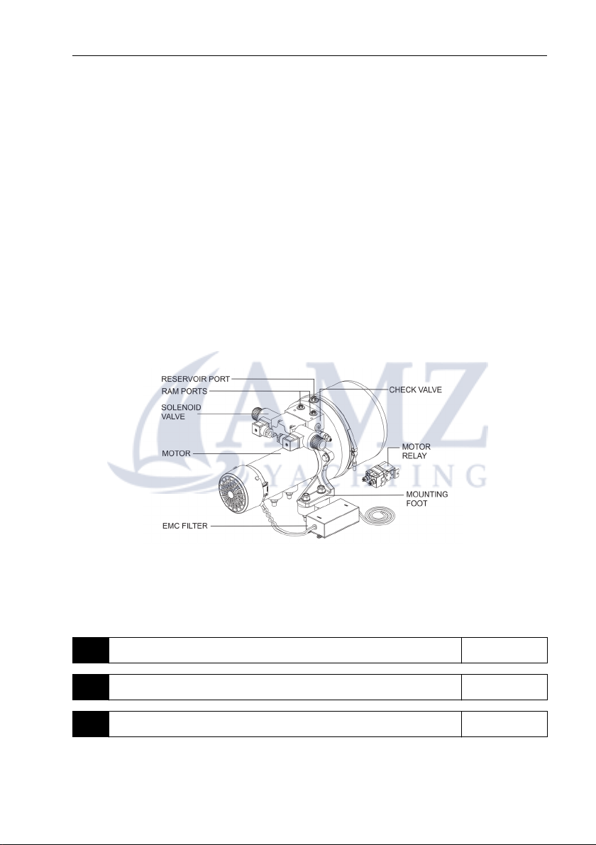
• The EMC filter box must not be removed from the motor cable.
Note: Where constraints on the installation prevent any of the above recommendations,
always ensure the maximum possible separation between different items of electrical
equipment, to provide the best conditions for EMC performance throughout the installa-
tion.
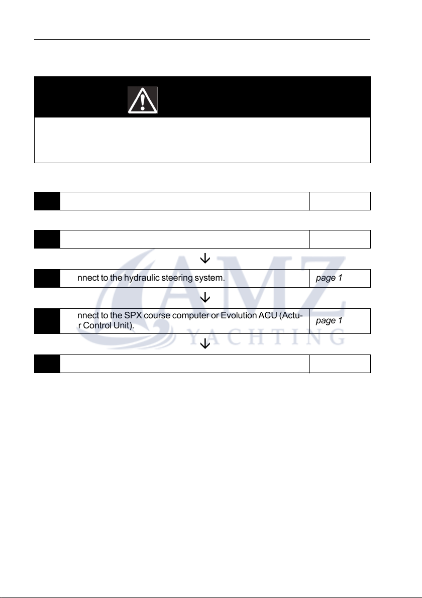
WARNING
Ensure cleanliness
Absolute cleanliness is essential when working with hydraulic systems.
Even the smallest dirt particle could prevent the steering system check
valves from working correctly. Ensure that no dirt enters the system during
the installation, and that all hoses and fittings are cleaned before making
any connections.