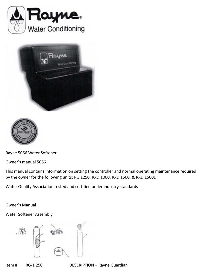
Rayne Versa User manual

Rayne Versa Service Manual
Water Conditioning
This manual contains information on setting the controller
and normal operating maintenance required by the owner.
This valve can be used on any tank but comes standard on the Rayne Versa Softeners listed on the
following page
Rayne Versa Service Manual
MODEL NUMBERS DESCRIPTION COMMENTS

—Upflow Models
RVU-1000 Upflow Brining, 1 cubic foot of resin U is for Upflow Brining
RVU-1500 1.5cubicfeetof resin
RVU-2000 2 cubic feet of resin
Downflow Models
RVD-1000 RVD-1000-M Downflow Brining, 1 cubic foot of resin D is for Downflow Brining
Msuffix is for adding the mixing valve to allow settings with some
hardness “bleed by”
RVD- 1500 RVD-1500M 1.5 cubic feet of resin
RVD-2000 RVD-2000-M 2 cubic feet of resin
Valve only
Rayne Versa Upflow Valve Valve only
Rayne Versa Downflow Valve Valve only
Rayne Versa DM Valve Valve only
Service Manual
Water Conditioning
ER Manual
ER Front Cover and Drive Assembly
Drawing No. Order No. Description Quantity
V3381-OIEG WS1ER FRONT COVER ASSEMBLY BLACKIGOLD 1

1V3381-01ES WS 1ER FRONT COVER ASSEMBLY BLACK/SILVER
2 V3107-01 WS1 MOTOR 1
3 V3106-01 WS1 DRIVE BRACKET & SPRING CLIP 1
4 V3491ER-01BOARD WS1 THRU 2L ER PC BOARD REPLACE 1
5 V3110 WS1 DRIVE REDUCING GEAR 12X36 3
6 V3109 WS DRIVE GEAR COVER 1
V3186 WS AC ADAPTER 11OV-12V 1
V186EU WS AC ADAPTER 220..240V-12V EU
Shown Not V3186UK WS AC ADAPTER 22O-240V-12VUK
V3186-01 WS1 AC ADAPTER CORD ONLY
Not Shown V3382 WS1ER DRIVE BACK PLATE
For software revs E203.6 and lower
Relay Specifications: To insure proper fit and correct operation use either of the 14cc relay/relay socket
combinations or the exact equivalents.
Manufacturer Option 1 Option 2
Relay Socket Idec SR3P-05C SY4S05C
Relay Idec RR2KP-UAC12V / RR2KP-LJCACl2V RY2KS-UACl2V
The relay supplies 2 sets of dry contacts for user applications.
The wiring of these contacts is application specific.
Wiring For Correct On/Off Operation
PC Board Relay Terminal Relay Socket Model
Block
SR3P.05C SY4S-05C
SET #2 #13
COM #6 and #l0 #12 and #14
RES #3 #9
For software revs E204.5 and higher
Relay Specifications: 12V DC Relay with a coil resistance not
less than 80 ohms. If mounting the relay under the cover check-

for proper mounting location dimensions on the backplate.
Wiring For Correct On/Off Operation
PC Board Relay Relay
Terminal Block
RLY1 Coil –
COM Coil +
AC Adapter U.S. International
Supply Voltage 120 VAC 230VAC
Supply Frequency 60 Hz 50 HZ
Output Voltage 12VAC 12VAC
Output Current 500 mA 500 mA
When replacing the battery, align
positives and push down to fully seat.
ER Manual
OEM General Instructions
The control valve offers multiple procedures that allow the valve to be modified to suit the needs of the
installation. These procedures are:
OEM Setup
OEM Softener System Setup
OEM Filter System Setup
Installer Display Settings
User Display Settings
Diagnostics
Valve History
Once the OEM Setup has been set, the other procedures can be accessed in any order. Details on each
of the procedures are provided on the following pages.
At the discretion of the manufacturer, the field technician can access all settings. To “lock out” access to
diagnostic and valve history displays and modifications to settings except hardness, day override, time of
regeneration and time of day by anyone but the manufacturer, press V. NEXT, ^, and SET CLOCK in
sequence after settings are made. To “unlock”, so other displays can be viewed and changes can be
made, press V, NEXT, ^, and SET CLOCK in sequence.

When in operation normal user displays such as time of day, gallons remaining before regeneration,
days remaining before regeneration or lbs. salt remaining before regeneration are shown. When
stepping through a procedure, if no buttons are pressed within five minutes, the display returns to a
normal user display. Any changes made prior to the five minute time out are incorporated.
To quickly exit OEM Softener Setup, OEM Filter Setup, Installer Display Settings, Diagnostics or Valve
History press SET CLOCK. Any changes made prior to the exit are incorporated.
When desired, all programming and information in Diagnostics may be reset to defaults when the valve
is installed in a new location. To reset to defaults, press NEXT and V simultaneously to go to the
Softening/Filtering screen. Press ^ and V simultaneously to reset programming and diagnostic values to
defaults. Screen will return to User Display.
Sometimes it is desirable to have the valve initiate and complete two regenerations within 24 hours and
then return to the preset regeneration procedure. It is possible to do a double regeneration if the
control valve is set to “NORMAL” or “NORMAL + on 0” in OEM Softener System Setup or OEM Filter
System Setup. To do a double regeneration:
Press the “REGEN” button once. REGEN TODAY will flash on the display.
Press and hold the “REGEN” button for three seconds until the valve regeneration initiates.
Once the valve has completed the immediate regeneration, the valve will regenerate one more time at
the preset regeneration time.
Proportional Brining
If the system is set up as a 1″ prefill upflow softener, the control valve can also be set to normal or
proportional brining.
SETThis step will appear after Step 7S and before Step8S if the system is set up as a prefill upflow
softener. The following options can be selected:
NORMAL FILL –System always prefills with the salt level selected.
ProP FILL –If proportional brining is selected, the actual salt fill time will be calculated by dividing @ the
actual volume of treated water used by the full volumetric capacity, then multiplying this value by the
maximum salt fill time.
Press NEXT to go to the next step. Press REGEN to return to the previous step.
OEM Setup
OEM Setup instructions allows the OEM to set meter size, dPswitch or alternating valve, pre or post fill
and dn or up brine where applicable. Fill and brine values are ignored when the system is set up as a
filter. The OEM Softener System Setup or the OEM Filter System Setup allow the OEM to set how long
cycles will last.
Step 1OS –Press NEXT and V simultaneously for 3 seconds and release. Then press NEXT and V
simultaneously for 3 seconds and release. If screen in Step 20S does not appear in 5 seconds the lock on
the valve is activated. To unlock press V. NEXT, ^, and SET CLOCK in sequence, then press NEXT and V

simultaneously for 3 seconds and release. Then press NEXT and V simultaneously for 3 seconds and
release.
Step 20S –Use ^ or V to select 1.0 for 1″ valve, 1.25 for 1.25″ valve, 1.5 for 1.5″ valve, 2.OL for 2L valve
or 2,0 for 2″ valve.
Note: When using the WS2 valve, if “2.0L” is set instead of “2.0”, when the valve is in regeneration
and the piston drives to the “DRAW” cycle the piston will stall and generate a 1002 error code. Clear the
error code by pressing “NEXT” and “REGEN” buttons simultaneously until the valve resets, then re-
program valve to proper valve type setting.
Press NEXT to go to Step 30S, Press REGEN to exit OEM cycle sequence.
Step 30S –When 2.0L, or 2.0 are selected, an additional screen will appear. It is used to select which
size flow meter is to be used with the valve, 1.5 or 2.0.
Press NEXT to go to Step 40S. Press REGEN to return to previous step.
‘When using the WS2 control valve, the circuit board software must have valve selection choices of 2.0
and 2.OL. The WS2 valve must be set for the 2.0 valve type during programming. If the software version
does not have both the 2.0 and 2.OL selections, consult your equipment supplier for a replacement
circuit board. When using the WS2L valve with older version software that does not have both 2.0 and
2.OL selection choices, the valve must be set to 2,0 during programming. If a WS2L valve is being used
with newer version software that has both 2.0 and 2.01, selection choices, the valve must be set to 2.OL
during programming.
Other notes:
Allows selection of one of the following using A or
the Control Valve to act as an alternator; or
the Control Valve to have a no hard water bypass: or
REGN • the Control Valve to have a Separate Source during the regeneration cycle.
Select OFF when none of these features are used.
Only use Clack No Hard Water Bypass Valves or Clack Motorized Alternating Valves (MAY) with
these selections. Clack No Hard Water Bypass Valves (1″ or 1.25″ V307OFF or V307OFM) are not
designed to be used with the alternator function or separate source mode.
Note: Clack Twin Alternator Operations
Twin alternating systems can be programmed with a day override setting combined with the normal
volume-based regeneration programming. A twin alternating system in this configuration will then
regenerate based on the volume used or the day override if there is a period of low water usage.

Twin alternating systems can be programmed as a time clock only based regenerating system. In this
configuration, the days remaining are counted only on the unit that is in service. The unit in Stand-by
Mode only notes days in diagnostics, which results in time clock only twin regeneration initiation.
Twin alternating systems can be programmed for a delayed regeneration time. The system will allow an
immediate transfer of the MAY to switch tanks and place a fully regenerated unit in service once a unit
becomes exhausted. The exhausted unit will then be placed into Stand-by Mode and allowed to have a
delayed regeneration at the pre-set time.
For Clack Corporation alternator systems using WS 1, WS1 .25, WS1.5, and WS21, valves there will be an
option to delay SET WS1, WS1.25, WS1.5,
WS2L Valves
For Clack Corporation alternator systems using the WS2 valve
WS2Valve
Er RLIR
Configuring the Control Valve for No Hard Water Bypass Operation:
a Clack No Hard Water Bypass Valve is made to the two pin connector labeled MAV DRIVE located on
the printed circuit board.
NOTE: If the control valve enters into an error state during regeneration mode, the no hard water
bypass valve will remain in its current state until the error is corrected and reset.
Configuring the Control Valve for Separate Source Operation:
Select “SEPS” for control operation. For separate source operation, the three wire connector is not used.
Selection requires that a connection to a Clack Motorized Alternator Valve (MAV) is made to the two pin
connector labeled MAV DRIVE located on the printed circuit board. The C port of the MAV must be
connected to the valve inlet and the A port connected to the separate source used during regeneration.
The B port must be connected to the feed water supply. When set to “SEPS”, the MAy will be driven
closed before the first regeneration cycle, and be driven open after the last regeneration cycle.
NOTE: If the control valve enters into an error state during regeneration mode, the MAy will remain in
its current state until the error is corrected and reset.
Press NEXT to go to Step 50S. Press REGEN to return to previous step.
The upfiow cycle may not be used on the WS 1.25, WS 1.5, WS2 or WS21, control valves, because the
V3407 and V3725 pistons are designed for downflow use only.
Versa Compatible fittings and accessories:
1″ PVC Male NPT Elbow Assembly; 3/4″ x 1″ PVC Solvent Elbow Assembly;1″ Brass Sweat Assembly LF

Order No. V360702LF 1.25″ Plastic Male NOT Assembly Order No. V3007.07 • Order V4007-091-
0 Order No. V3007.12
1″ SharkBite® Assembly 3/4″ John Guest QC ElboW Assembly
Order No. V30071 Order No.:V3OO715
Order No. V3007-031F 1.25″ & 1.5″ PVC Solvent Assi
Order No. V3007-05 3V SharkBite® Assembly
Table of contents
Other Rayne Water Dispenser manuals
Popular Water Dispenser manuals by other brands

Igloo
Igloo MWC496 Specification sheet

Judo
Judo QUICKSOFT-UNO Installation and operating instrictions

WaterLogic
WaterLogic WL4 Firewall Technical manual

Halsey Taylor
Halsey Taylor SW8 Series owner's manual

Halsey Taylor
Halsey Taylor GBVAKC*C owner's manual

Elkay
Elkay EZO Series Installation, care & use manual