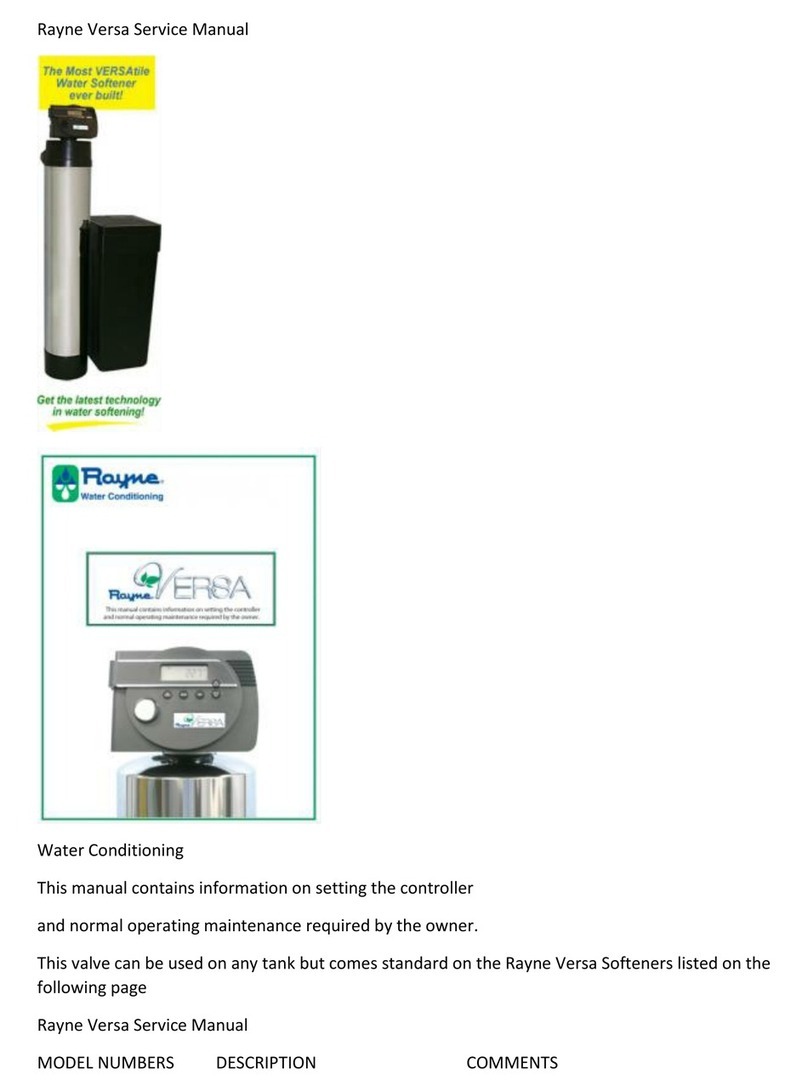
Rayne 5066 User manual

Rayne 5066 Water Softener
Owner’s manual 5066
This manual contains information on setting the controller and normal operating maintenance required
by the owner for the following units: RG 1250, RXD 1000, RXD 1500, & RXD 1500D
Water Quality Association tested and certified under industry standards
Owner’s Manual
Water Softener Assembly
Item # RG-1 250 DESCRIPTION –Rayne Guardian

15066103 RXD Controller –Specify Tank Size
1 A 18259-02 RXD Front Cover
2 60049 Bypass, plastic with 1″ yoke
3 RF0030 High Flow Distributor –Specify Tank Size
4 10 x 47 Mineral Tank
5 1/4 CF Filtrex Media
6 1-1/4 cf High Capacity Resin, Solvent Free
7 8 lbs. Support Bed –Gravel
8 10″ Collar –Black
9 Stainless Steel Jacket
10 10″ Tank Base
Item # RXD 1000 RXDI000S* RXD 1500 RXDI500-D Description
1 5066103 RXD Controller -Specify Model
2 60049 Bypass, plastic 1″
3 ST1040 ST1035 ST1047
10 x 40 10 x 35 10 x 47 Mineral Tank
4 RF00011 n/a RF00011 Tank Base
5 RF0030 High Flow 1′ Distributor – Specify Model
6 A1020-5 High Capacity Resin, C-249
1 cf 1cf 1.5 cf 1.5 cf
7 CK1040 n/a CK1040 SS1047
Almond Almond Stainless Steel jacket
10×40 10×47 10×47
8 RF00015 n/a RF000I5 SS0010 Collar –Black
9 n/a CK1111 n/a n/a Cabinet
10 n/a CK0011 n/a n/a Cabinet Deck
* Model RXD 1000S is not WQA Certified.

Item # RG-1 250 DESCRIPTION
1 C10772 BR 15″ x 17″ Complete Brine Tank Assembly
2 B08802 BR 15″ x 17″, Black Brine Tank
3 A10171 BR 15″ x 17″, Black Brine Tank Lid
4 A11510 BR Brine Line
5 A13940 BR Overflow Fitting
6 A14120 BR Brine Well
7 A05300 BR (2) Brine Well Lid
8 2310/500 Brine Valve Assembly
Owner’s Manual
Control Valve Assembly
Owner’s Manual
Brine Tank Assembly

Owner’s Manual
Down Flow Control Valve
Item No Quantity Part No Description
1 …………. ….1 ………..18815……………Valve Body, 5000, 1 “Dist.
2…………. ….1 ……….. 18264…………………..Spacer, End
3……….. ……4 ………..14241 …………………..Spacer
4…………….. 5 ………..13242………………….. Seal
5…………… 1 ………..18265………………….. Piston, Downflow
6…………….. 1 ………..14309………………….. Retainer, Piston Rod
7…………….. 1 ………..18268………………….. End Plug Assembly
8…………….. 3 ………..18261 ………………….. Screw, Hex Washer Head, 1024 x 13/16
9…………….. 1 ………..18267………………….. Piston Rod
10 ……….. 1 ………..17978………………….. Brine Valve Stem
11 ……….. 1 ………..18755………………….. Seat, Brine Valve
12 ………….1 ………..13167………………….. Spacer, Brine Valve
13 …………1 ………..12550………………….. Quad Ring, 009
14 ……….. 2 ………..13302………………….. 0 Ring, 014
15 ……….. 1 ……….. 13165 …………………… Cap, Brine Valve

16 ……….. 1 ………..11973 ………………….. Spring, Brine Valve
17 …………1 ………..16098………………….. Washer, Plain, Nylon
18 ……….. 1 ………..11981 01 ……….. Retaining Ring
19 ……….. 1 ………..11183 ………………….. 0 Ring, 017
20 ………. 1 ………..2.4 GPM ……….. Flow Washer
21 ……….. 1 ………..11385 01 ……….. Flow Control Housing, Plastic
22 ……….. 1 ………..18312………………….. Retainer, Drain
23 ……….. 1 ………..13304………………….. 0 Ring, 121
24 ……….. 1 ………..18303………………….. 0 Ring, 336
25 ……….. 2 ………..10141 ………………….. 0 Ring, 010
26 ……….. 1 ………..18276………………….. Plug, Injector
27 ……….. 2 ………..13771 ………………….. 0 Ring, 012
28 ……….. 1 ………..18275 X………….Injector Throat (specify size) 000, 00, 0, 1, 2, 3
29 …………1 ………..18274 X ………….Injector Nozzle (specify size) 000, 00, 0, 1, 2, 3
30 ……….. 1 ………..18273………………….. Vortex Generator
31 ……….. 1 ………..18271 ………………….. Screen Injector
32 ……….. 1 ………..18301 ………………….. Seal, Injector
33 ……….. 1 ………..18277………………….. Cap, Injector, Softener
34 ……….. 2 ………..18262………………….. Screw, Hex Washer Head, 10 24 x 1
35 ……….. 1 ………..12977………………….. 0 Ring, 015
36 ……….. 1 ………..13245………………….. Retainer, BLFC Button
37 ……….. 1 ………………………………………. Flow Washer (specify size)
38 ……….. 1 ………..13244………………….. Adapter, BLFC
39 ……….. 1 ………..13308………………….. Hose Barb, Black, 1/2 x 112 Straight
1 ………….12338 …………………. Hose Barb, Black, 1/2 x 1/2 900 Elbow
40 ……….. 1 ………….18280 …………………. Top Collector, 1 X.011, Gray
Owner’s Manual
Control Drive Assembly

Item No Quantity Part No. Description
1 …….. ………..1 .. ….EB5066………. Electronic Board
2 …………… ….1 . …..60200-00 ……. Control Drive Assembly, Downflow
3 …………….. ..1 .. ….18217-10 ……. Motor Assembly 24V /60 Hz
4 ………….. …..2 …… 13602 ………… Screw, Rd Head, 6-32 x 5/16
5 ……………. …2 ……18261 ………… Screw, Hex Head, 10-24 x 13/16
6 …………… ….1 … …13363 ………… Washer, Plain .145 ID
7 ………….. …..4 …. ..13296 ………… Screw, Hex Washer 6-20 x 1/2
8 ………… …….1 … …18259-02……. Cover, Back, Black
Owner’s Manual
Turbine Meter Assembly

Item No. Quantity Part No Description
1 ….. 1 .. 19797 ………………..Meter Assembly, Turbine
2 …… 1 . 13314 ………………..Screw, Hex Washer, 18-18 x 5/8
3 ………. 1 19569 ………………..Clip, Flow Meter
4 ………. 1 19791-01 ……………Meter Cable Assembly, Turbine
5…………… 4 ..13305 ………………..0 Ring, 119
6 ………. 4 14613 ………………..Flow Straightener
Owner’s Manual
By-Pass Assembly

Item No. Quantity Part No Description
1 …………… .1 …. .. 19723 ……………………By Pass Valve Body, Plastic
2 …….. ………..1 … …11183………………………..0 Ring, 015
3 …….. ………..1 … …19724 ……………………….Cap, By Pass
4…………. ……2 . …..17512 ……………..Screw, Hex Washer Head, #624×3
5 ……………. …2 …. ..17820 ……………………….Plug, By Pass
6 ………. ………4 … …18661 ……………………….0 Ring, 218
7 ….. …………..2 . …..18662 ……………………….Retaining Ring
8 ………… …….2 … …18660 ………………………. ORing
9 …….. ………..2 . …..13305 ……………………….0 Ring, 119
10 ……………..2 …. ..13255 ……………………….Clip, Mounting
11 ……………..2 … …13314 ……………………….Screw, Hex Washer Head, 818×5/8
12 …………1 18706………………………Yoke, Plastic, 1 “NPT
1 …. ..8706 02 …………………….Yoke, Plastic 3/4” (not pictured)
1 …. ..19620-01 …………90° Adapter Coupling – Optional (not pictured)
Owner’s Manual
2310\500 Safety Brine Valve Assembly
Item No Quantity Part No Description
1 . ………..1 ………….. 19645……………….. Safety Brine Valve Body

2…………….. 1 ………….. 19803……………….. Safety Brine Valve Arm Assembly
3…………….. 1 ………….. 19804……………….. Stud, 1024
4…………….. 1 ………….. 19805……………….. Nut, 1024
5…………….. 1 ………….. 1965201 …………… Poppet & Seal
6…………….. 1 ………….. 19649……………….. Flow Dispenser
7…………….. 1 ………….. 11183 ……………….. 0 Ring, 017
8 …………….. 1 ………….. 19647……………….. Elbow, Safety Brine Valve
9 …………….. 2 ………….. 19625……………….. Nut Assembly, 3/8
10…………… 1 ………….. 18312……………….. Retaining Clip
11…………. 1 ………….. 60014……………….. Safety Brine Valve, 2310 (includes
items 1 10)
12…………… 2 ………….. 10150……………….. Grommet (included with item 13)
13…………… 1 ………….. 60068 ……………….. Float Assembly, 2310
14…………… 1 ………….. 60002……………….. 500 Air Check Assembly
Owner’s Manual
Service Instructions
-To Remove and Replace Powerhead
Turn oft water supply to conditioner: a. If the conditioner installation has a “three valve” by pass system,
first open the valve in the bypass line, then close the valves at the conditioner inlet and outlet.
If the conditioner has an integral by pass valve, put it in the by pass position. c. If there is only a shut off
valve near the conditioner inlet, close it. 2. Relieve water pressure in the conditioner by putting
the control in the backwash position momentarily. Return the control to the service
position. 3. Unplug electrical cord from outlet. 4. Disconnect the cable from the meter
cover. Remove the control valve back cover. 5. Remove screw and washer at drive yoke. Remove
powerhead mounting screws. The entire powerhead assembly will now slide forward.
Put new powerhead on top of valve. Place lugs atop end plug and slide rearward. Be sure
drive pin on main gear engages slot in drive yoke (rotate control knob if necessary). 7. Replace
powerhead mounting screws. Replace screw and washer at drive yoke.
Return by pass or inlet valving to normal service position. Water pressure should now
be applied to the conditioner, and any by pass line shut off.9. Plug electrical cord into outlet. 10.
Set time of day, program wheel, and salt usage. Cycle the control valve manually to assure proper

function. Make sure the control valve is returned to the service position. 11. Replace the control
valve back cover. Set top leading edge of cover over the 2 legs and rotate down 12. Make sure there is
enough brine in the brine tank.13. Plug cable into meter cover. 14. Press the Extra Cycle button to
allow the unit to regenerate that evening.
To Remove and Replace Motor 1. Follow steps Al through A4. 2. Remove the clear Motor Bearing on the
front face of the powerhead by turning clockwise. 3. Disconnect wire nuts on motor leads and
powercord. 4. Remove the two screws holding motor in place and pull motor out of powerhead.
Note:You may have to rock motor slightly to theside. 5. Place new motor in position. Motor
should setflush with powerhead and install the two screws.6. Reconnect motor leads and powercord
and installwire nuts. Note: Motor leads should be wrapped clockwise around the motor coil to
keep clear of the mechanical operation of the
Control Valve.
Install the clear Motor Bearing on the front face of the powerhead. B. To Replace or Clean Injectors and
Screen 1. Follow steps Al through A3. 2. Remove the two screws in the injector cap. Remove injector cap
and discard seal. With screwdriver, pry injector nozzle and throat assembly from valve body. 3. Push in
cleaned or new injector nozzle and throat assembly. Be sure they are all the way in. Clean or install a
new screen. 4. Install new Injector cap seal in Valve Body. 5. Insert screws through injector cap into
mating 6. holes in the valve body and tighten screws. 7. Return by pass or inlet valving to normal service
position. Water pressure should now be applied to the conditioner and any by pass line shut off. Check
for leaks at seal around injector cap. C. To Replace Piston and/or Seals and Spacers and/or Brine Valve
Follow steps A1 through A.5. Remove the three screws and pull upward on end plug and piston
assembly to remove it from
Valve Body.
To Replace Brine Valve a. Pull brine valve from valve body, also remove
and discard o ring at bottom of brine valve hole b. Apply silicone lubricant to new o ring andreinstall at
bottom of brine valve hole. c. Apply silicone lubricant to new o ring on new brine valve assembly and
press into place, shoulder on bushing should be flush with valve body. 4. To Replace Seals and Spacers:
a. Remove seals and spacers using your fingers from valve body. b. Inspect the inside bore of the valve
for foreign matter that could interfere with valve operation. c. Replace new seals and spacers using your
fingers to set in place. 5. To Replace Piston: a. Inspect the inside of the valve to make sure that all seals
and spacers are in place, and that there is no foreign matter that could interfere with valve operation.b.
Take new piston and end plug assembly as furnished and push piston into valve by means of the end
plug.6. Install and tighten the three screws in the end plug.7. Return by pass or inlet valve to normal
service position. Water pressure should now be applied to the conditioner and any by pass line shut off.
Check for leaks at all seal areas. 9. Follow steps A6 through A14. E. To Replace Meter
Turn off water supply to conditioner: a. If the conditioner installation has a “three valve” by pass system,
first open the valve in the by-pass line, then close the valves at the condi-tioner inlet and outlet. b. If the
conditioner has an integral by pass valve, put it in the by pass position. c. If there is only a shut off valve

near the conditioner inlet, close it. 2. Relieve water pressure in the conditioner by putting the control in
the backwash position momentarily. Return the control to the service position. 3. Unplug electrical cord
from outlet.4. Disconnect the cable from meter assembly. 5. Remove two screws and clips at by pass
valve or yoke. Pull resin tank away from plumbing connections.6. Remove two screws and clips at
control valve. Pull meter module out of control valve. 7. Apply silicone lubricant to four new o rings and
assemble to the four ports on new meter module.8. Assemble meter to control valve. Note, meter
portion of module must be assembled to valve outlet. 9. Attach two clips and screws at control valve. Be
sure clip legs are firmly engaged over lugs. 10. Push resin tank back to the plumbing connections and
engage meter ports with by pass valve or yoke. 11. Attach two clips and screws at by pass valve or yoke.
Be sure clip legs are firmly engaged over lugs. 12. Return by pass or inlet valving to normal service
position. Water pressure should now be applied to the conditioner, and any by pass line shut off. 13.
Check for leaks at all seal areas. 14. Plug electrical cord into outlet. 15. Set time of day. Make sure the
control valve is in the service position. 16. Plug cable into meter assembly. F. Replace Filtrex media 1.
Approximately every 2 years contact your local Rayne Dealer.
Owner’s Manual
Trouble Shooting Guide
SYMPTOM
Softener fails to
regenerate automatically.
PROBABLE CAUSE CORRECTION
Cord plugged into intermittent A.Connect to constant power
or dead power source. source.
Disconnected meter cable. B. Reconnect cable
Defective power cord. C.Replace cord.
D.Defective controller or meter. D.Replace or repair.
SYMPTOM
Regeneration at wrong time.
PROBABLE CAUSE CORRECTION

A.Controller improperly set, due A.Reset timer
to Power failure B. Check battery.
SYMPTOM
Loss of capacity.
PROBABLE CAUSE CORRECTION
A.Increased raw water hardness. A.Connect to constant
automatically.
B.Brine concentration and for quantity. B.Keep full of
salt at all times. Clean
it yearly. Salt may be
bridged.
Resin Fouling. C.Call dealer, find out how
to confirm it, clean the
resin and prevent future
fouling.
D.Poor distribution, Channeling D.Call dealer. Check
(uneven bed surface). distributors and
backwash flow.
E.Internal valve leak. E.Call dealer. Replace
spacers, seals and/or
piston.
F.Resin age. F.Call dealer. Check for
resin oxidation caused
by Chlorine. Mushy resin.
G.Resin loss. G.Call dealer. Check for correct
bed depth. Broken distributors. Air or gas in

bed: Well gas eliminator Loose brine line.
SYMPTOM
Poor water quality.
PROBABLE CAUSE CORRECTION
Check items listed in #3. A. Check items listed in #3.
Bypass valve open. B. Close bypass valve.
Channeling. C. Check for too slow or high
flow. Check for media fouling.
SYMPTOM
High salt usage.
PROBABLE CAUSE CORRECTION
High Salt setting. A. Adjust salt setting.
Excessive water in brine tank. B. See symptom No. 7.
SYMPTOM
Loss of water pressure
PROBABLE CAUSE CORRECTION
A.Scaling/Fouling of inlet pipe A.Clean or replace pipeline.
or dead power source. Pre-treat to prevent.
B.Fouled resin. B. Clean the resin.Pre-treat to
prevent.
Improper backwash. C.Too many resin fines and/or
sediment. Call dealer, reset
backwash flow rate, and/or
adjust time.

SYMPTOM
Excessive water in brine tank
and/or salty water to service.
PROBABLE CAUSE CORRECTION
A.Plugged Drain Line A.Check flow to drain, clean
flow control.
B.Dirty or damaged brine valve. B.Clean or replace brine valve.
Plugged injector C.Clean injector and replace screen.
D.Low inlet pressure. D.Increase pressure to allow
injector to perform properly (20 psig minimum).
E.Timer not cycling. E.Replace timer.
SYMPTOM
Softener fails to use salt.
PROBABLE CAUSE CORRECTION
A.Plugged/restricted drain line. A.Clean drain line and/or flow
control.
B.Injector is plugged. B. Clean or replace injector and
screen.
No water in brine tank. C.Check for restriction in BLFC.
Ensure safety float is not stuck.
D.Water pressure is to low. D.Line pressure must be at least
20 psi.
E.Brine line injects air during brine draw. E.Check brine line for air leaks.
F.Internal control leak. F.Call dealer, check piston, seals,and spacers

for scratches and dents.
SYMPTOM
Control cycles continuously.
PROBABLE CAUSE CORRECTION
A.Faulty timer. A.Replace timer.
SYMPTOM
Continuous flow to drain.
PROBABLE CAUSE CORRECTION
A.Faulty timer. A Call dealer, clean valve,
rebuild unit.
B.Internal control leak. B. Same as above.
Valve jammed in brine C.Same as above
refill unit.
Valve motor stopped or jammed. D.Replace valve motor.
60015 1610 Brine Valve
For Illustration, see page 10
1 ……………. 11973 ………….. Spring, Brine Valve
1 …………… 11981 01 ……… Retaining Ring
1 …………… 12550………….. Quad Ring, 009
1 …………… .13165 ………….. Cap, Brine Valve
1 …………… 13167 ………….. Spacer, Brine Valve

2…………… 13302………….. 0 Ring, 014
1 …………… 16098 ………….. Washer, Plain, Nylon
1 …………… 17978 ………….. Brine Valve Stem
1 …………… 18755………….. 0 Ring, 201
6002212 ……… BLFC.1125 GPM
6002225 ……… BLFC.25 GPM
6002250 ……… BLFC.50 GPM –Standard
60022100 ……. BLFC 1.0 GPM
1 ………….. 17307 …….. …… Flow Washer. 125 GPM
12094………….. Flow Washer.25 GPM
12095………….. Flow Washer.50 GPM
12097………….. Flow Washer 1.0 GPM
1 …………..12977………….. 0 Ring, 015
1 …………..13244 ………….. Adapter, BLFC
1 …………..13245 ………….. Retainer, BLFC
6011500 ……… Piston Assembly, Downtlow
1 …………..14309 …………..Retainer, Piston Rod
1 …………..18265 …………..Piston, Downflow
1 …………..18267 …………..Piston Rod
1 …………..18268 …………..End Plug Assembly
60120…………..Seal and Spacer Kit
5 …………..13242…………..Seal
4 …………..14241 …………..Spacer
1 …………..18264…………..End Spacer
18272000 ……. 1610 Injector Assy., 000, Brow
1827200……… 1610 Injector Assy., 00, Violet
182720 ……….. 1610 Injector Assy., 0, Red
182721 ……….. 1610 Injector Assy., 1, White
182722 ……….. 1610 Injector Assy., 2, Blue

182723……….. 1610 Injector Assy., 3, Yellow
1 ………….10141 …………… 0 Ring, 010
1 ………….13771 …………… 0 Ring, 012
1 ………….18273…………… Vortex Generator
1 …………..18274 XX……… Injector Nozzle
1………….18275 XX……… Injector Throat
60280 0001610 Injector Kit, 000, Brown
6028000 1610 Injector Kit, 00, Violet
602800 1610 Injector Kit, 0, Red
602801 1610 Injector Kit, 1, White
Model 1000 & 1500
602802 1610 Injector Kit, 2, Blue –
Model 2000
602803 1610 Injector Kit, 3, Yellow
1 …………….18271 …………..Screen, Injector
1 ……………..18272 XX………..1610 Injector Assembly
1 ……………..18277 …………….Cap, Injector
1 ……………..18301 …………….Seal, Injector
2 ……………..18262 …………….Screw, Hex Washer Head,
10 24 x 12
CD5066 Control Drive Assembly
60086-50 …. 3/4″ Meter
60049……….Bypass, Plastic
6070500 ….. DLFC BLANK
6070506 ….. DLFC .60 GPM
6070508 ….. DLFC .80 GPM
6070510 ….. DLFC 1.0 GPM
6070512 ….. DLFC 1.2 GPM
6070513 ….. DLFC 1.3 GPM

6070515 ….. DLFC 1.5 GPM
60705 17….. DLFC 1.7 GPM
6070520 ….. DLFC 2.0 GPM
6070524 ….. DLFC 2.4 GPM
Model 1250
6070530 ….. DLFC 3.0 GPM
60705 35 …. DLFC3.5 GPM
60705 40 …. DLFC 4.0 GPM
6070545 ….. DLFC 4.5 GPM
6070550 ….. DLFC 5.0 GPM
6070560 ….. DLFC 6.0 GPM
6070570 ….. DLFC 7.0 GPM
1 …………….11183 0 Ring, 017
1 …………………..11385 01 ….. DLFC Housing Plastic
Flow Washer (specify size)
Table of contents
Other Rayne Water Dispenser manuals
Popular Water Dispenser manuals by other brands

GE
GE GXSF30V02 Owner's manual and installation instructions

Everpure
Everpure CG53-20 Specification sheet

MOA
MOA HWD25W instruction manual

WaterSoft
WaterSoft rs1 Installation and operation manual

Halsey Taylor
Halsey Taylor WM14A-BL-Q-1Q Series owner's manual

Black & Decker
Black & Decker 900143 user manual

Emerson
Emerson HC-View-SS Installation & use manual

Culligan
Culligan Aquasential Select Plus Series owner's guide

Clean Water
Clean Water VORTEXER user guide

Hague Quality Water
Hague Quality Water HomeGuard 400 Owners and installation manual

Everpure
Everpure IN-6 CG-S EV9100-66 Specification sheet

USTM
USTM WS-12-C-1650 Manual instruction