RayTalk RB-130 User manual

IEEE 802.11b Outdoor Wireless Client Bridge
User Manual
September 24, 2004
Version 1.01
Before operating the unit, please read this manual thoroughly, and
retain it for future reference.
Version 1.01 i
■
Contents
CHAPTER 1. INTRODUCTION................................................................1
1.1 INTRODUCING THE KIT MAN BRIDGE........................................................1
1.2 PRODUCT FEATURES ..............................................................................1
1.3 PACKAGE CONTENTS..............................................................................1
1.4 SYSTEM REQUIREMENTS.........................................................................1
1.5 INLINE POWER INJECTOR (POE)..............................................................2
CHAPTER 2. INSTALLATION AND BASIC CONFIGURATION.........3
2.1 BEFORE YOU START...............................................................................3
2.2 LOCATE THE RB-130 AND INLINE POWER INJECTOR PORTS......................4
2.3 PREPARING INSTALLATION .....................................................................6
2.4 BASIC CONFIGURATION ..........................................................................7
2.4.1 What you need to know..................................................................7
2.4.2 Basic Configuration Steps.............................................................7
2.4.3 Logging into the Web Interface .....................................................8
2.4.4 Set Operating Mode, IP Address, Subnet Mask, Default Route IP,
DNS Server IP of KIT MAN BRIDGE .........................................................12
2.4.5 Set Wireless Encryption for Wireless Interface ............................13
2.4.6 Change Supervisor Account & Password.....................................13
2.4.7 Upgrade the Firmware ................................................................14
2.4.8 Back-up the RB-130’s Configuration Files..................................18
CHAPTER 3. NETWORK TOPOLOGIES.............................................21
3.1 WIRELESS CLIENT BRIDGE-TO-CENTRAL WIRELESS BRIDGE..................22
3.2 WIRELESS CLIENT ROUTER-TO-CENTRAL WIRELESS BRIDGE .................23
3.3 WIRELESS CLIENT BRIDGE-TO-CENTRAL WIRELESS ROUTER .................24
3.4 WIRELESS CLIENT ROUTER-TO-CENTRAL WIRELESS ROUTER ................25
CHAPTER 4. NETWORK PARAMETERS............................................27
4.1 IP CONFIGURATION..............................................................................27
4.2 VIRTUAL SERVER.................................................................................28
4.3 CONFIGURE SNMP ..............................................................................30
4.3.1 Configure Community Pool.........................................................30
4.3.2 Configure Trap Host Pool ...........................................................32
4.4 CONFIGURE WIRELESS RELATED PARAMETERS.......................................33
4.5 SECURITY............................................................................................36
4.5.1 MAC based Access Control.........................................................36

Version 1.01 ii
4.6 ADVANCE............................................................................................37
4.6.1 Transparent Bridge .....................................................................37
4.7 UTILITY...............................................................................................38
4.7.1 Software Upgrade........................................................................38
4.7.2 Administration.............................................................................39
CHAPTER 5. MONITOR INFORMATION............................................41
5.1 SYSTEM INFORMATION.........................................................................41
5.2 STATISTIC INFORMATION......................................................................43
5.3 WIRELESS LINK INFORMATION..............................................................44
CHAPTER 6. SPECIFICATIONS............................................................45
6.1 HARDWARE SPECIFICATIONS.................................................................45
6.2 SOFTWARE SPECIFICATIONS..................................................................47
CHAPTER 7. DEFAULT SETTINGS......................................................48
7.1 GENERAL CONFIGURATION...................................................................48
7.1.1 System.........................................................................................48
7.1.2 Virtual Server..............................................................................48
7.1.3 SNMP..........................................................................................49
7.1.4 Wireless LAN ..............................................................................50
7.1.5 MAC filter...................................................................................51
7.1.6 Advance ......................................................................................51
7.2 UTILITY...............................................................................................51
7.2.1 Software Upgrade........................................................................51
7.2.2 Administration.............................................................................51
CHAPTER 8. REGULATORY COMPLIANCE INFORMATION........52
Version 1.01 1
Chapter 1. Introduction
1.1 Introducing the KIT MAN BRIDGE
The KIT MAN BRIDGE is a fully interoperable with IEEE 802.11b compliant
Outdoor Wireless Last-mile product. The RB-130 operates in remote bridge
mode, and connects Outdoor Wireless Router Bridge to construct point-to-point
as well as point-to-multipoint topologies, for maximum flexibility in configuring
building-to-building networks to WISP.
1.2 Product Features
Outdoor enclosure in compliance with IP67
RF transmit power 100mW (20dBm) with -85dBm Rx
sensitivity @ 11Mbps data rate
Embedded 9dBi patch directional antenna
Support 24VDC 0.8A Power-over-Ethernet
NAT/NAPT and Virtual Server Mapping support
MIB-II and Private MIB support
MAC address based access control
1.3 Package Contents
The product package contains the following items.
1. One (1) RB-130 Outdoor Wireless Client Bridge unit
2. One (1) 100~240VAC, 50~60Hz AC/DC adapter with wall-
mount plug and DC plug power cord
3. One (1) 24VDC, 830mA Inline Power Injector (PoE)
4. One (1) 30m RJ-45 CAT-5 Ethernet cable
5. One (1) 1.8m RS-232 null modem console cable
6. One (1) 1.8m grounding wire
7. One (1) User manual CD-disc
8. One (1) wall/mast mounting kit, including one (1) band clamp
1.4 System Requirements
Installation of the Outdoor Wireless Client Bridge requires the following:

Version 1.01
1. A Windows-based PC/AT compatible computer or Ethernet
data device with an available RJ-45 Ethernet port to run the
configuration program or with TCP/IP connection to the
Ethernet network.
2. A 10/100Base-T Ethernet RJ-45 Ethernet cable is connected to
Ethernet network.
3. A RS-232 consol port cable is connected to PC/AT compatible
computer.
4. An AC power outlet (100~240V, 50~60Hz) supplies the power.
1.5 Inline Power Injector (PoE)
The RB-130 is equipped with an Inline Power Injector module. The Inline
Power Injector (PoE) delivers both data and power to RB-130 unit via a
signal Ethernet cable, and gives the following benefits to improve the
performance vs. installation cost ratio.
1. This works great in areas where you may not have power
and/or Ethernet easily accessible, like house roof.
2. This also allows you to place the RB-130 unit closer to the
antenna, more easily thus reducing signal loss over antenna
cabling.
3. Ethernet signal travels well over CAT 5 cable but 2.4GHz
signal doesn't do as well over antenna cabling.
4. Ethernet cabling is much cheaper than Antenna cabling.
Version 1.01
Chapter 2. Installation and Basic Configuration
This chapter describes the procedures of installing the RB-130.
2.1 Before You Start
After unpacking the system, make sure the following items are present and
in good condition.
1. RB-130 Outdoor Wireless Client Bridge unit
2. AC/DC adapter 100~240VAC, 50~60Hz with wall-mount plug
and DC plug power cord
3. Inline Power Injector (PoE) 24VDC, 830mA
4. RJ-45 CAT-5 Ethernet cable 30m
5. RS-232 null modem console cable 1.8m
6. Grounding wire 1.8m
7. User manual CD-disc
8. Wall/mast mounting kit, including one (1) band clamp
2
3
4
5
7
8
6
1

Version 1.01
2.2 Locate the RB-130 and Inline Power Injector
Ports
Interface on the RB-130 Unit
Ethernet Port 1for connecting the 30m RJ-45 CAT-5 Ethernet
cable.
RS-232 Console Port 2for connecting the 1.8m RS-232 null
modem console cable.
Interface on the Inline Power Injector
Data Input Port 3for connecting cross-over Ethernet Cable to
PC or straight Ethernet cable to Hub Switch Router.
110~240VAC, 50~60Hz AC/DC power adapter DC Input Port
4
Power & Data Output Port 5for connecting the 30m RJ-45
CAT-5 Ethernet Cable.
Grounding Port 6.
NOTE: The cross-over or straight type Ethernet cable is not provided in
RB-130 shipping package as an accessory. User can find one from
computer store in accordance with the length required for indoor
deployment.
3
1
2
6
5
4
Version 1.01
Mount RB-130 on A Wall/Pole
The RB-130 can be mounted on the wall, you can use the Wall Mount kit to
mount the RB-130 as shown in Figure 2.2.1.
Figure 2.2.1
You can also mount the RB-130 to the mast as shown in Figure 2.2.2.
Figure 2.2.2
Chapter 2. Network Topologies
This section describes several main types of installations commonly
implemented using the Outdoor Wireless Router/Bridge System (RB). This
is by no means intended to be an exhaustive list of all possible
configurations, but rather shows examples of some of the more common
implementations. The RB can be configured into two roles: Central
Router/Bridge (CRB) and Remote Extension Router/Bridge (RRB) to
accomplish the broadband wireless point-to-point, point-to-multipoint
systems (as shown in following figuration).
Both the Central RB and the Remote RB can performed in router or bridge
modes. In a Point-to-Multipoint topology, all communication between
network systems is done through a centralized agent. In the Outdoor
Wireless Router/Bridge product, the centralized agent is Central Router or
Central Bridge and the individual network notes may be Remote Router or
Remote Bridge.
To show some possibilities of Point-to-Multipoint topologies, the following
examples are provided:
1. Remote Wireless Bridge-to-Central Wireless Bridge
2. Remote Wireless Router-to-Central Wireless Bridge
3. Remote Wireless Bridge-to-Central Wireless Router
4. Remote Wireless Router-to-Central Wireless Router
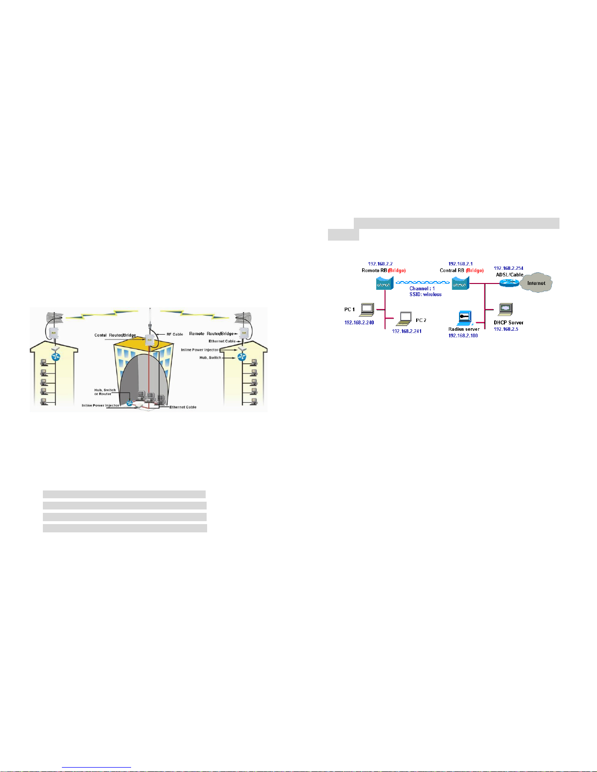
2.1 Remote Wireless Bridge-to-Central Wireless
Bridge
1. Set the Central RB as a bridge (bridge IP address is 192.168.2.1).
2. Set Wireless parameters on Central RB: Channel (1) and SSID
(wireless)
3. Set the Remote RB as a bridge (bridge IP address is 192.168.2.2).
4. Set Wireless parameters on Remote RB: Channel (1) and SSID
(wireless), these parameters must same with Central RB.
5. Left side subnet is transparent to the right side.
6. DHCP server assign IP address to PC1 and PC2

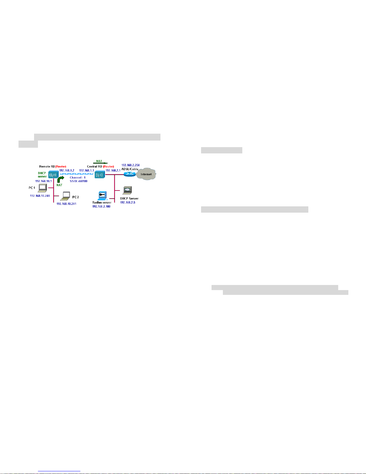
2.2 Remote Wireless Router-to-Central Wireless
Bridge
1. Set the Central RB as a bridge (bridge IP address is 192.168.2.1).
2. Set Wireless parameters on Central RB: Channel (1) and SSID
(wireless).
3. Set the Remote RB as a Router (Wireless Interface IP is 192.168.2.2,
Ethernet Interface IP is 192.168.10.1, must turn on NAT on Wireless
Interface, default route is 192.168.2.254).
4. Set Wireless parameters on Remote RB: Channel (1) and SSID
(wireless), these parameters must same with Central RB.
5. Set the DHCP server service on the Remote RB and apply it on
Ethernet Interface.
6. The Remote RB assign IP address to PC1 and PC2
2.3 Remote Wireless Bridge-to-Central Wireless
Router
1. Set the Central RB run as a Wireless Router (Wireless Interface IP is
192.168.1.1, Ethernet Interface IP is 192.168.2.1, must turn on NAT on
Ethernet interface, default route is 192.168.2.254).
2. Set Wireless parameters on Central RB: Channel (1) and SSID
(wireless)
3. Set the DHCP server service on the Central RB and apply it on
Wireless Interface.
4. Set the Remote RB as a Bridge (Bridge Interface IP is 192.168.1.2).
5. Set Wireless parameters on Remote RB: Channel (1) and SSID
(wireless), these parameters must same with Central RB.
6. The Central RB assign IP address to PC1 and PC2
7. The operator can also turn off NAT behavior on Central RB and
two subnets are transparent.
2.4 Remote Wireless Router-to-Central Wireless
Router
1. Set the Central RB run as a Wireless Router (Wireless Interface IP is
192.168.1.1, Ethernet Interface IP is 192.168.2.1, default route is
192.168.2.254).
2. Set Wireless parameters on Central RB: Channel (1) and SSID
(wireless).
3. Set the Remote RB as a Wireless Router (Wireless Interface IP is
192.168.1.2, Ethernet Interface IP is 192.168.10.1, default route is
192.168.1.1).
4. Set Wireless parameters on Remote RB: Channel (1) and SSID
(wireless), these parameters must same with Central RB.
5. Set the DHCP server service on the Remote RB and apply it on
Ethernet Interface.
6. The Remote RB assigns IP address to PC1 and PC2.
The operator can also turn off NAT behavior on Central RB and turn
on NAT behavior on Remote RB. In this case, any outgoing packets
will transfer to 192.168.1.2
Remote RB: turn on NAT on Wireless Interface.
The operator can also turn on NAT behavior on Central RB and turn
on NAT behavior on Remote RB.
Central RB: turn on NAT on Ethernet interface.
Remote RB: turn on NAT on Wireless Interface.
Chapter 3. Web Access
Web Connection
The Outdoor Wireless Access Router/Bridge (RB) supports access to the
configuration system through the use of an HTTP Interface (web browser).
Before configuring the RB, you need to know the IP Address assigned to
the unit.
When shipped from the factory, the IP Address (192.168.2.1) was assigned
to the RB by default. To start a web connection use:
http://192.168.2.1/
Identify the IP Address assigned to the unit
However, the IP Address may be changed and you cannot connect the unit
using the default IP Address. In this case, you must identify the RB IP
Address before configuration. To identify the IP Address, you can use the
Serial Port to gain access the current network status. To start a Serial Port
connection:
1. Attach a serial data (RS-232) cable to the Serial Port Adapter.
Connect the other cable end to a terminal or a PC running a terminal
emulation program. Use a 9-pin female to 9-pin female NULL Modem
cable.
2. Set the terminal to 115200 Baud, No-Parity, 8 data bits, 1 Stop bit,
and ANSI compatible.
Note: Running a terminal emulation program on your PC, such as
HyperTerminal, and then set the following connection properties:
Click the Start icon > Program > Accessories >
Communication > Terminal.
Create a new connection file, and then select a Com Port
<COM1, COM2, etc., depending on your PC> with 115200bps /
8-bits / 1-stop.
Click the properties icon in the Tool Bar > setting > select
Emulation terminal VT100 > ok.
3. Reboot or turn on your RB
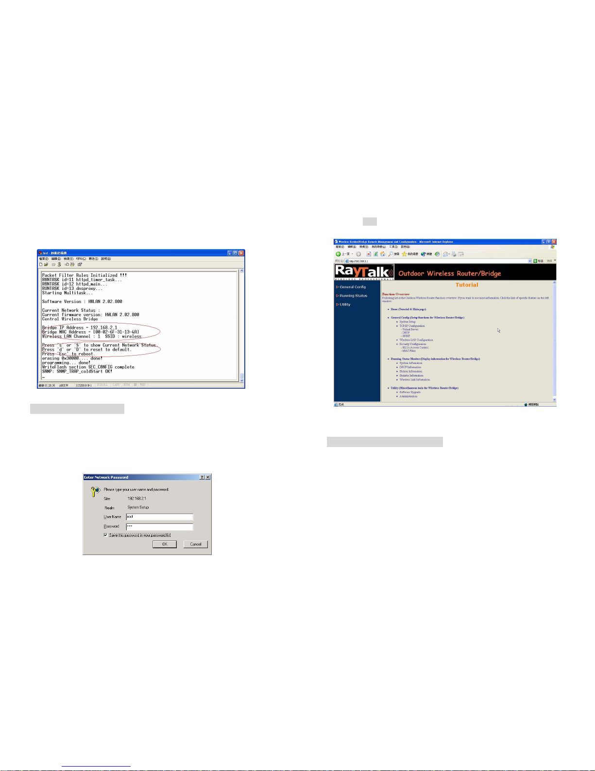
4. When the RB is powered up, the “Current Network Status”will be
displayed.
Figure 3-1 Current Network Status
Web Access Procedure
Once you identify the IP Address assigned to your OWRB, use your web
browser to configure the OWRB through the HTTP Interface.
The following procedure explains how to configure each item.
1. Open your browser and enter the IP Address
2. Press ENTER and the RB Login screen appear.
Figure 3-2 Login Screen
3. Enter root in the User Name and the Password fields. And then the
web configuration user interface screen appears.
Figure 3-3 Web User Interface
Web Configuration Structure
The web configuration user interface be grouped in a tree structure, and
contains the following settings or information:
▽ General Configuration
● System
● TCP/IP
-Virtual Server
-DHCP
-Routing
-SNMP
● Wireless
● Security
-802.1X Access
-MAC Filter
● Firewall

● Advance
▽ Running Status
● System Info
● DHCP Info
● Station Info
● Statistic Info
● Wireless Link Info (Remote Extension RB only)
▽ Utility
● Software Upgrade
● Administration
Move through the tree by clicking on an icon to expand or collapse the tree.
The nodes on the tree represent web pages that allow you to view and
modify the parameters.
Figure 3-4 Web Configuration Structure
Chapter 4. Configuration
4.1 Introduction
What you Need to Know
The RB can be configured into two operation roles:
Central Wireless Router/Bridge (Central RB) and Remote Wireless
Router/Bridge (Remote RB).
Central RB can performed in four operation modes:
Central Wireless Bridge
Central Wireless Router with PPPoE Ethernet connection
Central Wireless Router with dynamic IP address Ethernet
Central Wireless Router with static IP address Ethernet
Remote RB can performed in two operation modes:
Remote Wireless Bridge
Remote Wireless Router
The RB is shipped with default configuration is as a bridge between an
Ethernet and wireless network. Users simply need to attach the RB to your
wired LAN. If users would like to configure the RB, please refer to the
following procedures.
4.1.1 Basic Configuration Steps
Modify the Default Settings and Apply the New
This section will describe a 5-step configuration to setup your Outdoor
Wireless Router/Bridge (RB) workable.
1. Select an operation mode for your RB on the web page “/General
Config/System/”, and click FINISH to refresh this page.

2. Modify the factory-set default parameters on the web page “/General
Config/System/”page, and click FINISH to save your changes.
3. Modify the factory-set default parameters on the web page “/General
Config/Wireless/”page, and click FINISH to save your changes.
4. (Optional) Modify others parameters on the web page “/General
Config/”page, and click FINISH to save your changes.
5. Move on page “/Utility/Administration/”, select the Save then
Restart and then click FINISH to take effect the previous
configuration changes.
4.2 System Setup
When setting up a Wireless Router/Bridge (RB), you must decide which
operation mode that your RB works. This feature is available in the
“/General Config/System/”page.
Figure 4-1 & 4-2 show the “General Configuration –System Setup”
page.
Figure 4-1 General Configuration –System Setup-1
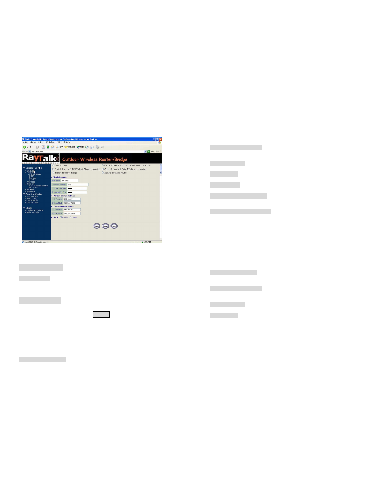
Figure 4-2 General Configuration –System Setup-2
Host Information
- Host Name. The Host Name is not an essential setting, but it helps
identify the device in network. Use this setting to assign a name to the
device.
Operation Mode
The First Thing You Have To Do
Select an operation mode, and click FINISH to refresh this page.
4.2.1 Wireless Access Bridge
Select the Central Wireless Bridge mode. And then set the corresponding
parameters.
- Bridge IP Address. Use this setting to assign or change the bridge’s IP
address.
- Bridge Subnet Mask. Enter an IP subnet mask to identify the sub
network so the IP address can be recognized on the LAN.
Default Route IP
- IP Address. Enter the default Gateway IP Address.
DNS Server IP
- Primary DNS Server IP. Enter the Primary Domain Name Server IP
Address.
- Secondary DNS Server IP. Enter the Secondary Domain Name Server
IP Address.
After that, click FINISH at the bottom of this page to complete the
modification of this page.
4.2.2 Remote Extension Bridge
Select the Remote Wireless Bridge mode. And then set the corresponding
parameters.
- Bridge IP Address. Use this setting to assign or change the bridge’s IP
address.
- Bridge Subnet Mask. Enter an IP subnet mask to identify the sub
network so the IP address can be recognized on the LAN.
Default Route IP
- IP Address. Enter the default Gateway IP Address.
After that, click FINISH at the bottom of this page to complete the
modification of this page.

4.2.3 Central Router with PPPoE Client Ethernet
connection
If you are an ADSL subscriber, you need to specify that you personal ISP
PPPoE Username and Password to enable ADSL broadband access.
- PPPoE User Name. This setting allows you to enter the user name that
your ISP assigns to your account.
- PPPoE Password. Enter the password that your ISP assigns to your
account.
- Password Confirm. Enter the PPPoE Password once more again.
Wireless Interface Address
- IP Address. Use this setting to assign or change the wireless interface’s
IP address.
- Subnet Mask. Enter an IP subnet mask to identify the sub network so the
IP address can be recognized on the WLAN.
Ethernet Interface Address
- IP Address. Use this setting to assign or change the Ethernet interface’s
IP address
- Subnet Mask. Enter an IP subnet mask to identify the sub network so the
IP address can be recognized on the WAN.
NAPT performs on which interface?
There are three interfaces. You can select one to use or select "None"
to disable it.
Default Route IP
- IP Address. Enter the default Gateway IP Address.
DNS Server IP
- Primary DNS Server IP. Enter the Primary Domain Name Server IP
Address.
- Secondary DNS Server IP. Enter the Secondary Domain Name Server
IP Address.
After that, click FINISH at the bottom of this page to complete the
modification of this page.
4.2.4 Central Router with DHCP Client Ethernet
connection
Wireless Interface Address
- IP Address. Use this setting to assign or change the wireless interface’s
IP address.
- Subnet Mask. Enter an IP subnet mask to identify the sub network so the
IP address can be recognized on the WLAN.
NAPT performs on which interface?
There are three interfaces. You can select one to use or select "None"
to disable it.
Default Route IP
- IP Address. Enter the default Gateway IP Address.
DNS Server IP
- Primary DNS Server IP. Enter the Primary Domain Name Server IP
Address.
- Secondary DNS Server IP. Enter the Secondary Domain Name Server
IP Address.
After that, click FINISH at the bottom of this page to complete the
modification of this page.
4.2.5 Wireless Router with static IP Ethernet connection
Wireless Interface Address
- IP Address. Use this setting to assign or change the wireless interface’s
IP address.
- Subnet Mask. Enter an IP subnet mask to identify the sub network so the
IP address can be recognized on the WLAN.

Ethernet Interface Address
- IP Address. Use this setting to assign or change the Ethernet interface’s
IP address
- Subnet Mask. Enter an IP subnet mask to identify the sub network so the
IP address can be recognized on the WAN.
NAPT performs on which interface?
There are three interfaces. You can select one to use or select "None"
to disable it.
Default Route IP
- IP Address. Enter the default Gateway IP Address.
DNS Server IP
- Primary DNS Server IP. Enter the Primary Domain Name Server IP
Address.
- Secondary DNS Server IP. Enter the Secondary Domain Name Server
IP Address.
After that, click FINISH at the bottom of this page to complete the
modification of this page.
4.2.6 Remote Extension Router
Wireless Interface Address
- IP Address. Use this setting to assign or change the wireless interface’s
IP address.
- Subnet Mask. Enter an IP subnet mask to identify the sub network so the
IP address can be recognized on the WLAN.
Ethernet Interface Address
- IP Address. Use this setting to assign or change the Ethernet interface’s
IP address
- Subnet Mask. Enter an IP subnet mask to identify the sub network so the
IP address can be recognized on the WAN.
NAPT performs on which interface?
There are three interfaces. You can select one to use or select "None"
to disable it.
Default Route IP
- IP Address. Enter the default Gateway IP Address.
DNS Server IP
- Primary DNS Server IP. Enter the Primary Domain Name Server IP
Address.
- Secondary DNS Server IP. Enter the Secondary Domain Name Server
IP Address.
After that, click FINISH at the bottom of this page to complete the
modification of this page.

4.3 TCP/IP Protocol Configure
4.3.1 Virtual Server Mapping
Sometimes, the operator can expose the internal servers on the local
intranet to the public Internet. For this, you must create the Virtual Server
Mapping for these invisible internal servers.
Select the “/General Config/ Virtual Server/”, and then the General
Configuration - Virtual Server screen appears. Figure 4-3 show the
current virtual server entry table. (Default Virtual Server Mapping pool is
empty)
Figure 4-3 General Configuration - Virtual Server
1. Click Add .The Virtual Server Entry Edit page Figure 4-4 appears.
2. To edit the Virtual Server Entry, specify all the entry fields to allow
Internet user to access the Internal servers.
Service Name: Alias name of this internal server, such as FTP.
Access Interface: Indicate the translation occurs on which interface
(Wireless interface / Ethernet interface), such as Ethernet.
Protocol: Indicate which protocol (TCP/UDP) you want to translate
from outside to internal server, such as TCP.
Public Access Port number: Indicate which socket port (1 ~ 65535)
you want to translate from outside to internal server, such as 21.
Virtual Server IP address: Specify the private IP address of the
internal server, such as 192.168.1.100.
Virtual Server Port number: Specify the socket port (1 ~ 65535) of
the internal server, such as 21.
3. Click OK . The Virtual Server Entry Table appears with the entries list.
4. To modify or delete a virtual server entry, click the select button beside
the entry index number and click Modify or Delete .
5. To add another entry to the Virtual Server Mapping Pool, repeat step 1
through step 3.
6. When you have included all the entries you need, click FINISH .
Figure 4-4 Add Virtual Server Entry
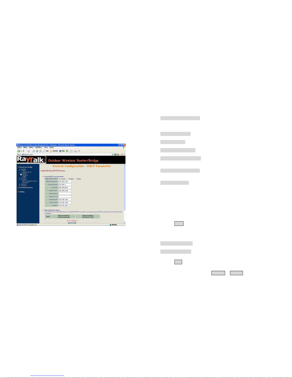
4.4 Configure DHCP server
Sometimes, the operator want to managing a large TCP/IP network
requires maintaining accurate and up-to-date IP address and domain name
information. In this situation, it needs manually configure and enable the
DHCP server service. Select the “/General Config/ DHCP/”, and then the
General Configuration –DHCP Parameter screen appears. Figure 4-5
shows the general DHCP parameters and the fixed host entry table.
(Default fixed host entry pool is empty).
Figure 4-5 DHCP Parameter
4.4.1 General DHCP Server Parameter
- Trigger DHCP Service. Select Enable to allow the RB to assign
IP Addresses from IP Pool Table. Select Disable to prevent IP Address
assignment from the RB
- Default Gateway. Enter the default Gateway IP Address.
- Subnet Mask. Configure the subnet for the client.
- Name Server 1, 2, 3. Configure the DNS servers IP for the client.
- DHCP Start IP address. Enter the starting IP Address for this IP Pool
Table.
- DHCP End IP address. Enter the ending IP Address for this IP Pool
Table.
- Apply Interface. Enable DHCP server service on Wireless or Ethernet
interface.
4.4.2 Fixed Host Entries
Figure 4-5 shows the general DHCP parameters and the fixed host entry
table. (Default fixed host entry pool is empty).
1. Click Add .The Fixed Host Entry Edit page Figure 4-6 appears.
2. To edit the Fixed Host Entry, specify the Ethernet and Internet Address
fields.
- Ethernet Address. Enter the MAC address for a fixed IP user.
- Internet Address. Assign a fixed IP Address to this special user.
3. Click OK . The Fixed Host Entry Table appears with the entries list.
4. To modify or delete a fixed host entry, click the select button beside the
entry index number and click Modify or Delete .

5. To add another entry to the Fixed Host Mapping Pool, repeat step 1
through step 3.
6. When you have included all the entries you need, click FINISH .
Figure 4-6 Add Fixed Host Entry
4.5 Routing
Click General Config, Routing, and then the General Configuration –
Routing Parameter screen appears. Figure 4-7 shows the current static
route table.
Figure 4-7 General Configuration –Routing Parameter
Click 'Delete' or 'Modify' button to delete or modify static route entry. Input
new static route and click 'Add' button to add entry. Configure items include
Network Address, Subnet Mask and Gateway Address.
After that, click FINISH at the botton of this page to complete the
modification of this page.

4.6 Configure SNMP
Click General Config, SNMP, and then the General Configuration –SNMP
Community Parameter screen appears. Figure 4-8 shows the current
SNMP community pool and trap host pool.
Figure 4-8 General Configuration –SNMP Community Parameter
4.6.1 Configure Community Pool
The SNMP Community Pool has five entries.
1. To modify a entry, click the select button beside the entry index
number and then click Modify ,the configuration page Figure 4-9
appears.
2. Specify the Validity, Access Right and Community field.
- Validity. Select Enable or Disable to control this community.
- Access Right. Select a command from the pull down menu for this field.
- Community. Enter the password related the Access Right in this field.
3. Click OK . To refresh the current community pool.
4. To modify another community entry to the current community pool,
repeat step 1 through step 3.
5. When you have modified all the entries you need, click FINISH .
Figure 4-9 Modify SNMP Community Parameter
4.6.2 Configure Trap Host Pool
The Trap Host Pool has five entries.
1. To modify a entry, click the select button beside the entry index
number and click Modify .The configuration page Figure 4-10
appears.
2. Specify the Version, IP Address and Community field.

- Version. Select Disable, Version 1 or Version 2 to control this trap host.
- IP Address. Enter the Trap Host IP Address.
- Community. Enter the password in this field.
3. Click OK . To refresh the current trap host pool.
4. To modify another trap host entry to the current trap host pool, repeat
step 1 through step 3.
5. When you have modified all the entries you need, click FINISH .
Figure 4-10 Modify SNMP Trap Host Parameter
4.7 Configure Wireless related parameters
Click General Cofig, Wireless.The Wireless LAN information page
Figure 4-11 appears. In here, enter the Transmit Power (default is 20dB) ,
Channel (default is 1), Domain(default is Europe) ,rts Threshold (default
is 1600), frag Threshold (default is 1600), SSID (default is wireless) and
Station Name (default is ap) that are suitable for your radio network and
then you can clicked radio button to disable WEP or enable 64/128 bit
WEP services (default is disable), if WEP is enabled, you must input
corresponded Default Key index and WEP Key and then click KeyGen
to generate the WEP64 & WEP128 key patterns. After that, click FINISH at
the bottom of this page to complete the modification.
Figure 4-11
- Transmit Power. This setting determines the transmit power which can
choice 8 to 23 dB
- Channel. The factory setting is Radio Channel 1 transmitting at 2412
MHz. The channel set appears on the screen installed on your access.
Each channel covers 22 MHz. The bandwidth for channels 1, 6, and 11

does not
overlap, so you can set up multiple access point in the same vicinity
without causing interference.
- RTS Threshold. This setting determines the packet size at which the
bridge issues a request to send (RTS) before sending the packet. A low
RTS Threshold setting can be useful in areas where many client devices
are associating with the access point, or in areas where the clients are far
apart and can detect only the bridge and not each other. Enter a setting
ranging from 0 to 2339 bytes.
- Frag Threshold. This setting determines the size at which packets are
fragmented (sent as several pieces instead of as one block). Enter a setting
ranging from 256 to 2338 bytes. Use a low setting in areas where
communication is poor or where there is a great deal of radio interference.
- SSID. The Service Set ID (SSID) can be any alphanumeric, case-
sensitive entry from two to 32 characters long. This string functions as a
password to joint the radio network.
- Hide SSID. You use this setting to choose whether devices that do not
specify an SSID are allowed to associate with the access point. With Yes
selected, the SSID used by other devices must match exactly the AP’s
SSID.
- Deny Any. You use this setting to choose whether devices that specify
the well define SSID keyword ‘ANY’or ‘any’are allowed to associate
with the access point. With Yes selected, the SSID ‘ANY’or ‘any’used by
other devices are not allowed to associate with the access point
- Station Name. Enter any alphanumeric, case-sensitive entry.
- WEP Key. Enter 1~15 characters for 64 and 128 bits WEP KEY
encryption, and then click KeyGen to generate the WEP64 & WEP128
key patterns.
- WEP. Disable or enable 64/128 bit WEP services.
- Default Key. Select an encryption key from the pull down menu.
- WEP64 Key1~4 & WEP128 Key1~4. The keys in these fields can be
generated automatically by KeyGen function. For 40-bit encryption, enter
10 hexadecimal digits; for 128-bit encryption, enter 26 hexadecimal digits.
Hexadecimal digits include the numbers 0 through 9 and the letters A
through F. Your 40-bit WEP keys can contain any combination of 10
of these characters; your 128-bit WEP keys can contain any combination of
26 of these characters. The letters are not case-sensitive.
4.8 Security
4.8.1 802.1X Access control
1. Click Basic Config,select 802.1x Access control page, and choice
the 802.1x services is Enable or Disable (as shown in Figure 4-12).
Figure 4-12
2. IF you choice 802.1x services Enable , you can select Accessible
802.1x Users on Local or Remote Radius Server
3. If you choice 802.1x Users on Remote Radius Server , you need
setup
Radius parameters

- Radius server IP Enter the radius server IP Address.
- Share key Enter the share key. (default is key)
- Radius authentation port (default is 1812)
- Radius acconnecting port (default is 1813)
4. If you choice 802.1x Users on Local , You can specify the Local user
of a wireless client station. All Local user entries in the Local user
database are permitted to connect into the RB. You can also click
ADD, DELETE, MODIFY button to maintain this Local user database.
After that, click FINISH at the bottom of this page to complete the
modification of this page
4.8.2 MAC based Access Control
1. Click Basic Config,select MAC Filter page, and choice the MAC
Filter services is Enable or Disable (as shown in Figure 4-13).
2. You can specify the MAC address of a wireless client station. All MAC
entries in the MAC address table are permitted to connect into the
RB. You can also click ADD, DELETE, MODIFY button to maintain
this MAC address table. After that, click FINISH at the bottom of this
page to complete the modification of this page.
Figure 4-13
4.9 Configure Firewall
Figure 4-14
- Firewall Service. Click General Config,select Firewall page, and
choice the Firewall services is Enable or Disable (as shown in Figure 4-
14).
- Rule Name. You can describe rule name as you wish for this firewall rule.
- Schedule. choice the Firewall rule is Enable or Disable
Table of contents
Popular Network Hardware manuals by other brands

Cisco
Cisco OL-6109-01 user guide

Digiever
Digiever DS-2100 UHD Series Quick installation guide

Wisenet
Wisenet XRN-410S Quick manual

Cabletron Systems
Cabletron Systems Cabletron BRIM-F6 user guide

COM-power corporation
COM-power corporation LI-1100C instruction manual

Huawei
Huawei EchoLife HG8245Q quick start


