Raytec URBAN-X Pro User manual

www.rayteccctv.comRaytec Global Tel: +44 (0) 1670 520055
Americas Tel: +1 613 270 9990
Box Contents
• URBAN-X Pro luminaire
• URBAN-X Pro pole mount arm
• 2 x Fixing grub screws
• 1 x Cable Tie
• 2 x M8 screw
• 2 x M8 washer
• 2 x M8 spring washer
• Lightweight and durable design
•Excellentefcacy>140lm/W
• The luminaires are Class 1 for
insulation
• Intelligent driver programs
•5-yearwarranty
• The luminaires are suitable for use
outdoors and indoors
Safety Warnings
Eye Safety:
Caution–EN62471RiskGroup2Classication-Possiblehazardousoptical
radiationemittedfromthisproduct.Maybeharmfultoeyes,donotstareatthe
lamp.HazardDistanceis2,750mm.
Warning: High Voltage product
AllElectricalInstallationworktobeperformedbyasuitablyqualiedpersonin
line with the local regulations.
Riskofelectricshock-isolatemainsbeforeremovingcover.
Mechanical Installation:
Ensureunitismountedsecurelytopreventriskofinjuryandthesupplycordisinstalledas
per the instructions. Maximum mounting height 12M.
URBAN-XProInstallationGuide
Ver.1.1-04/19

www.rayteccctv.com Raytec Global Tel: +44 (0) 1670 520055
Americas Tel: +1 613 270 9990
Installation Steps
TheURBAN-XProisdeliveredintwoparts;themainbodyoftheluminaire,andthepolemount
arm.Thesetwopartsmustbeassembledpriortoinstallation.Thesupplycableneedstobetted
priortoassembly(unlesstheunitissuppliedwithasupplycablealreadytted).
Formodelswithoutasupplycablepre-tted,gotostep(1).Formodelswithasupplycable
pre-tted,gostraighttostep(2).
Important Information:
Asuitablyrated3corecable(5coreforusewithDALI)mustbeused.
ConductorsizeCSA:0.75mm2to1.0mm2
CableO/D:Min4.5mmtoMax10mm
(1) Connection procedure
• Loosen retaining screws from the lid of the luminaire
(2screws)andtiltthelidback.
• 3CoreMainssupplycable.
- Preparesuitable3coremainscableasshown.
• Feedthecableintotheunitviathecableglandtted
to the rear of the unit.
• Terminatemainssupplywirestotheterminalblock.
-(L)Live-(N)Neutral-()Earth
• Tighten the cable gland nut so the cable is held
securelyandtheenvironmentalsealismaintained
(20mmspannerrequired).
• Use the cable tie in the accessories bag to secure
the cable to the base plate. Pass the cable tie
underneath the white cable mount and around the
cable. Tighten and clip out the excess cable tie tail.
• Close the lid.
- Makesureallwiresareinsidetheproductand
nonearetrappedbythelid.
- Tightenthetwolidscrewsto4Nmtorqueto
ensure the environmental seal.
• DALI connection (when used):
- The additional cores should be stripped to
8.5mm–9.5mmandsuitablyterminated.
- Connectthetwowiresdirectlytothe
driverterminalslabelledDA(BL)Blue.
Theconnectionisnon-polaritysensitive.
70mm
80mm
=80mm
8mm
L&NWires=70mm

www.rayteccctv.comRaytec Global Tel: +44 (0) 1670 520055
Americas Tel: +1 613 270 9990
(3) Mechanical installation
• Mountunitonanappropriatelysizedpole(60–76mmdiameter).
• Secureunitontopoleusingsuppliedgrubscrews.Ensurepoleisfullyengagedandtighten
grubscrewstotorque17nm(5mmhex).
(2) Luminaire and Pole Mount Bracket Assembly
•Feedthesupplycablethroughthepolemountarmbeforesecuringittotheluminairesmainbody.
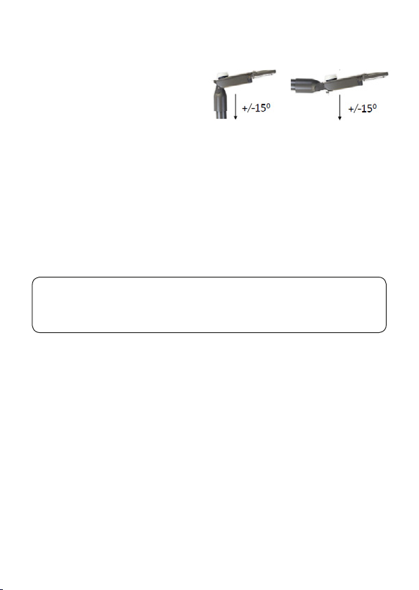
• The pole mount arm can be assembled in
a vertical orientation, with an angle range
tothevertical,orinahorizontalorientation,
withananglerangetothehorizontal.
•Alignthepolemountarmtothebackofthemainluminaireandlocatethetwomountingslotson
either side.
•Secure by using the M8 screws, M8 washer and M8 spring washer (one on each side) and
tightentotorque17nm.(thespringwasherislocatedbetweentheM8washerandtheheadof
theM8screw).
WARNING:
Ifthefactoryttedcableisdamageditmustbereplacedbyasuitablyqualiedpersonto
avoidahazard. The lightsourcecontained in thisluminaireshall onlybereplacedby the
manufacturer or a nominated representative.
Functionality
TheunitrespondswhenpowerissuppliedtotheinternalLEDdriver.IftheunithasaPhotocell
ttedthisactsasanon/offswitchforthepowerreachingtheinternalLEDDriver.(For Photocell
On/Off Lux Levels please see the specication table.)
Driver Programs (these are part of the product code and will be marked on the driver)
Theunitwillfunctionaccordingtooneofthefollowingfactory-setprograms;
ID1 - Soft Start: 100%outputfordurationofnight(5secondsoftstart).
ID2 - Timer Dimming: 100%power(5secondsoftstart)for5hoursfrompowerup,
then50%poweruntilthenextcycle.
*ID3 - Active Dimming 50%
*ID4 - Active Dimming 25%: 100%output(5secondsoftstart)frompowerup,thendimsto
either50%(ID3)or25%(ID4)power,aroundthemidpointof
thenightanduptoamaximumof6hoursafter,thenbackto
100%ifit’sstilldark.
Thisprogramwouldtypicallyrequiretheuseofaninbuiltor
remotephotocelltomonitorthehoursofdarkness.

www.rayteccctv.com Raytec Global Tel: +44 (0) 1670 520055
Americas Tel: +1 613 270 9990
Ensurealltestsareundertakenbyaqualied,
trainedengineer.Ensuresafeworkingpractices
are followed at all times.
• Checkmainsinput
• Checkallmainswiringconnectionsarecorrect
• Checkphotocellisworking(iftted)
• CheckDriverProgram
• Checkluminairephysicalalignment
• IfDALIcontrolledcheckDALIcommunications
and connections
• CallRaytecforfurtherassistance
Product Dimensions Urban-X PRO Troubleshoot
Model Type Urban X PRO 40W Urban X PRO 60W Urban X PRO 80W Urban X PRO 100W
Operating Temperature -30°C to 60°C (-22°F to 140°F) -30°C to 40°C
(-22°F to 104°F)
Power Output (Lumens) 5600 8400 11,200 14,000
Consumption 40W 60W 80W 100W
Input (nominal) 220-240V AC (50-60Hz)
Surge Protection Photocell tted: 2kV. No Photocell tted: 8kV
Weight (Excluding Cable) 4Kg (8.8lbs)
Photocell Switching (If tted) On at 55 Lux ; Off at 28 Lux
Environment IP66
Impact Protection IK08
Dimensions (L x W x H) 485 x 239 x 220mm (19.09 x 9.4 x 8.66”) (Height 242.5 mm /9.5” with photocell tted)
Optional Cable Length 8M (26ft) or 12M (39ft)
DALI control
• TheLEDdriverisDALIcompatibleallowing
furthercontrolfunctionalityandsimultaneous
control of multiple luminaires.
ATC
• The unit has inbuilt automatic thermal control
which protects the unit in high temperature
installationsbyturningtheLEDsdownto
prevent damage to the product.
Urban-X Pro Specications:
*Modelshownwithoutphotocelltted*
ID5 - Event Trigger: Theluminairewilloperateat100%for30minutesandthen
switch off until re-activated.
Custom: Acustomerspecicprogram.
* Notsuitableforlocationswherethelengthofnightis23hoursorgreater.Fortherst3nightstheluminaire
is on at 100% power from sunset to sunrise whilst the system learns the length of nights. Unit does not
compensateforvariationswithinlocaltimezones.Unitdoesnotcompensateforinternationalclockchanges.
485
220
239
Table of contents
Other Raytec Outdoor Light manuals
Popular Outdoor Light manuals by other brands

Velleman
Velleman CLB2 quick start guide

HUDSON VALLEY LIGHTING
HUDSON VALLEY LIGHTING mitzi JEN HL819201 installation instructions

Würth
Würth 0981 180 020 Translation of the original operating instructions

Wampat
Wampat PHANES W62P1302A Assembly/installation instructions

RH
RH PAXTON Assembly/installation instructions

Gama Sonic
Gama Sonic GS-97-SP instruction manual

WE-EF
WE-EF QRO359 LED Installation and maintenance instructions

Hornbach
Hornbach 10599897 quick start guide

LIGMAN
LIGMAN EURASIA 1 installation manual

Deco Lighting
Deco Lighting Small Gladetino installation guide

Hubbardton Forge
Hubbardton Forge 302570 Assembly/installation instructions

Vista
Vista 1447 installation instructions