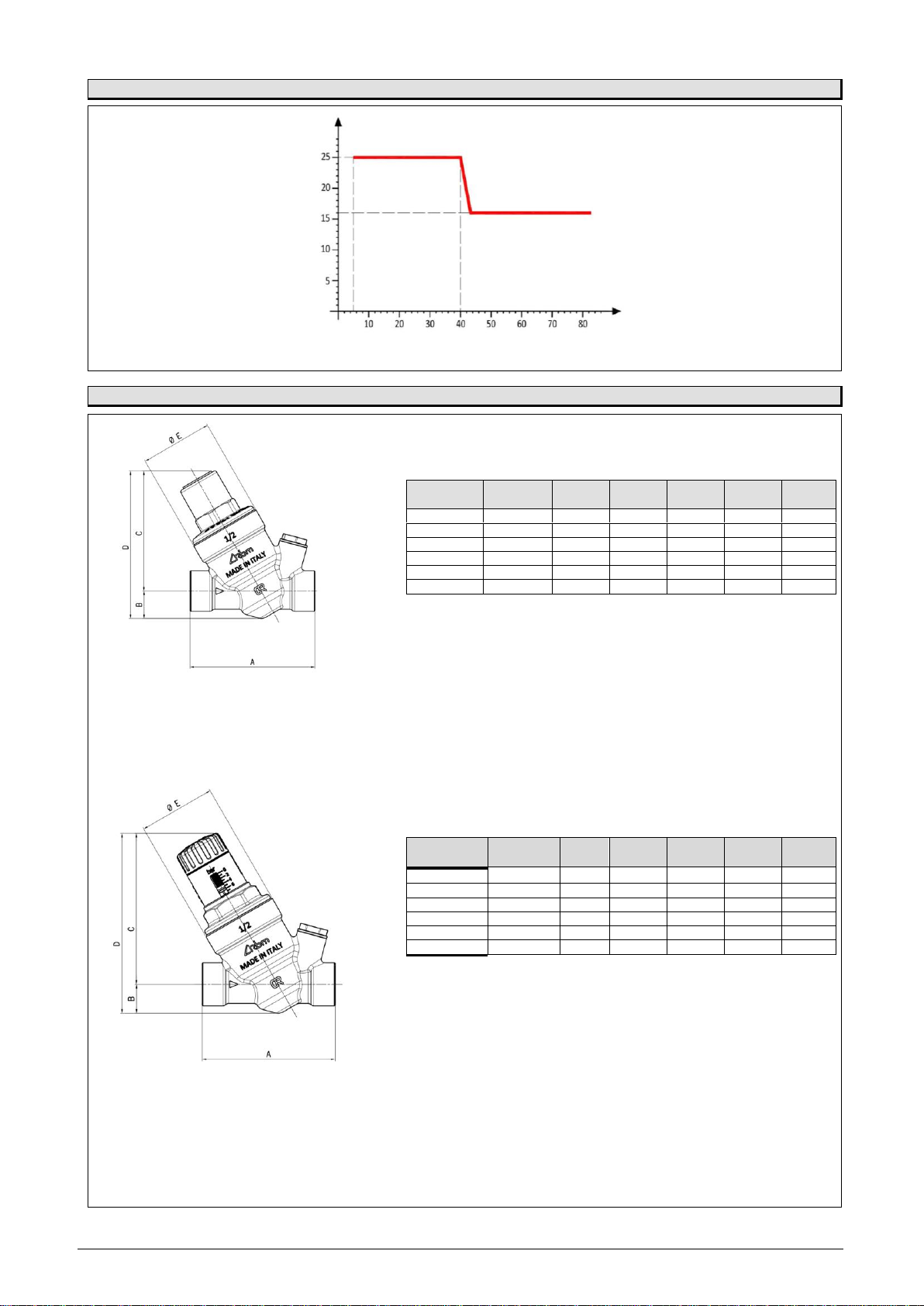
In order to avoid cavitation and therefore excessive noise of the component, it is recommended to dimension the number of pressure
reducers required for a certain pressure drop as described in the "CAVITATION DIAGRAM".
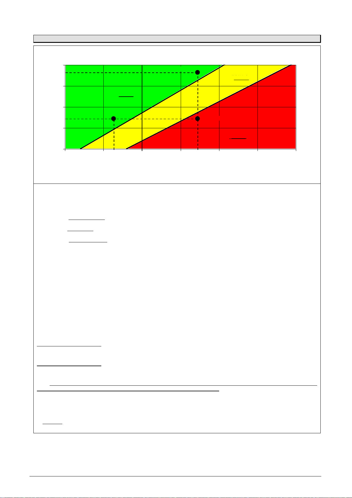
The cavitation diagram shows three areas of operation of the pressure reducer depending on the upstream and downstream
pressures:
•ZONE 1: Malfunction zone. The cavitation phenomena are clearly visible and present inside the reducer: avoid operating the
reducer at these pressures.
•ZONE 2: Critical zone. It highlights the possible creation of cavitation inside the reducer. We advise against operating the reducer
within this range of pressure values.
•ZONE 3: Zone of operation. The reducer works in optimal conditions and does not recess. The range of pressure values is
optimal for the operation of the reducer.
In order to avoid cavitation phenomena, it is recommended to run the reducer inside ZONE 3 and, also, avoid that the ratio between
the upstream maximum pressure and the downstream adjustment pressure of the reducer exceeds the value of 2.5.
DIMENSIONING
You wish to run a reducer within the following pressure values:
•P upstream: PM= 8.5 bar
•P downstream: PV= 1.5 bar
As you may notice from the diagram (POINT 1), at these operating pressure values, the pressure reducer meets certain cavitation
phenomena.
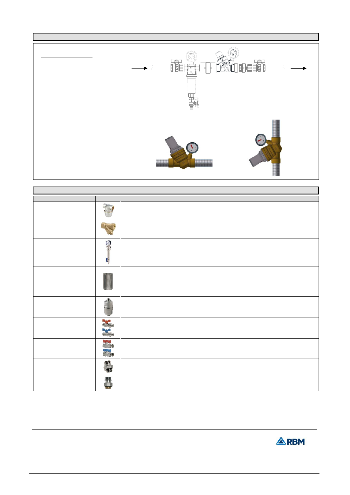
To avoid these phenomena, and taking into account that the ratio between the upstream maximum pressure and the downstream
adjustment pressure must not exceed the value of 2.5, you can introduce a second pressure reducer in series, in order to obtain the
same pressure drop through two distinct pressure jumps.
The possible solution, therefore, is to use two pressure reducers in series, that must both work in ZONE 3 of the diagram, split the
pressure difference on two reduction stages, with a pressure ratio not over 2.5.
Possible solution:
Pressure reducer A [POINT 2]:
•P upstream: PMA = 8.5 bar Pressure ratio: 8.5/3.5 = 2.4 < 2.5
•P downstream: PVA = 3.5 bar
Pressure reducer B [POINT 3]:
•P upstream: PMB = 3.5 bar Pressure ratio: 3.5/1.5 = 2.3 < 2.5
•P downstream: PVB = 1.5 bar
N.B.: The pressure downstream of the reducer must never be greater than the maximum operating pressure of the components,
which are downstream of the reducer itself, in order to avoid damage or malfunctioning.
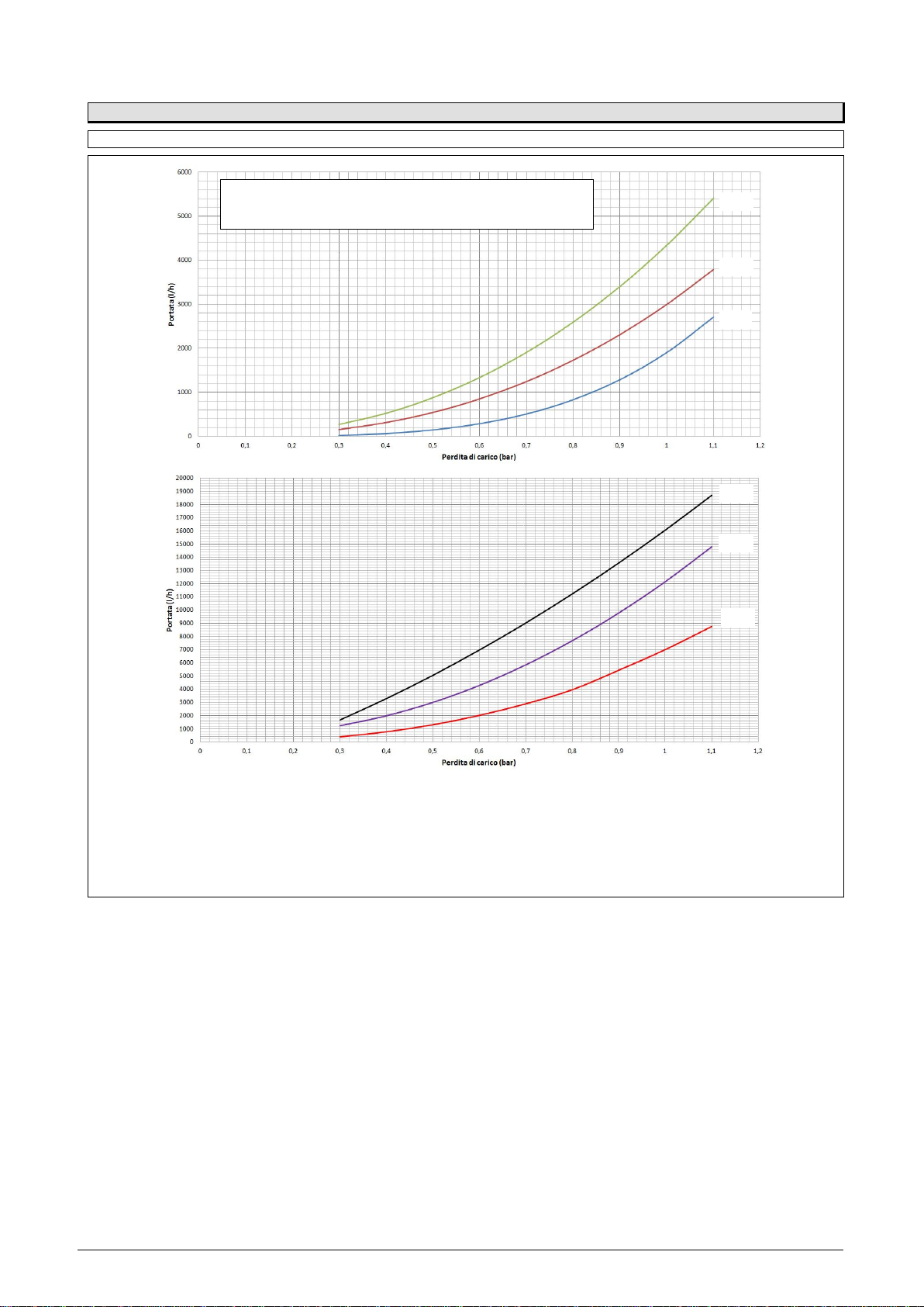
The cavitation of the pressure reducer can be checked, as well as by acting on the pressure difference, also by selecting an optimal
value of the speed of fluid passing through it.
It is advisable, therefore, to choose the diameter of the pressure reducer so that the speed of the fluid going through it, is contained
within the following values:
•For water: V = 0.7 ÷ 1.5 m / s (residential use)
V = 1 ÷ 3.5 m / s (industrial use)