RC Product Designs TC3-O V2 User manual

Page 1
TC3 “O” V2
RC Product Designs
Instruction Manual
TC3 "O" V2
4WD Off-Road Buggy Conversion Kit
for the Associated TC3
Kit #: DC-000B
Website Address: www.rcproductdesigns.com

TC3 “O” V2
RC Product Designs
Page 2
DC-000B V2 Kit Content:
⇒DC-001B – V2 Carbon Fiber Rear Shock Tower
⇒DC-002B – V2 Carbon Fiber Front Shock Tower
⇒DC-003B – V2 Carbon Fiber Center Drive Shaft
⇒DC-004B – V2 Carbon Fiber Chassis Brace
⇒DC-005B/006B – V2 Brass Steering Posts
⇒DC-007B – V2 Black Delrin Steering Spacer
⇒DC-008 - Tie Bar
⇒DC-009B/010B - Steering Knuckle Extensions
⇒DC-011B – V2 Black Delrin Wheel Hex Adapters
⇒DC-012 – MIP™ CVD Steel Bones (Set of 4)
⇒DC-013B – V2 Machined Black Delrin Front A-Arms
⇒DC-014B – V2 Machined Black Delrin Rear A-Arms
⇒DC-015B – V2 Nylon Reinforced Front Chassis Extension Plate
⇒DC-016B – V2 Modified Front and Rear Arm Mounts (Pivot Blocks)
⇒DC-017B – Black Delrin Servo Mounts
⇒DC-018 – V2 Front Shock Tower Mount
⇒DC-019 – V2 Rear Shock Tower Mount
⇒DC-020 – Decal Sheet
⇒DC-025 - Additional screws, nuts and washers
⇒DC-026 – Steel inner hinge pins
⇒DC-030 – V2 Body & Wing
⇒DC-U1516D – Front White smooth design (Dish) 2.2”
⇒DC-U1458X – Rear White smooth design (Dish) 2.2”
⇒DC-3872 – 4 Degree Front Block Carriers
⇒DC-9150 – B3 Servo Saver Kit (Steering Bell-Crank Kit)
⇒DC-7319 – Body Mounts
⇒DC-A4222 – Wing Mount Kit

Page 3
TC3 “O” V2
RC Product Designs
Tools Required
⇒Allen wrenches: 1/16" and 3/32"
⇒Molded tools from Associated
#6956
⇒Dremmel Cutting Tool & File
⇒Pencil
⇒1/8” & 3/16” drill & 82 degree
Countersink ¼” diameter
⇒Needle-nose pliers
Warning!
It is recommended to always wear
Eye Protection when using any
Power Tools and a Dust Mask if
grinding/sanding plastic, graphite
or metal parts.
Recommended Tools:
⇒3/32" driver
⇒1/16" driver
⇒3/16" nut driver
⇒11/32" nut driver
Parts you will need to complete the kit:
⇒R/C 2-channel surface frequency radio system.
⇒Battery pack (6 cell).
⇒Electronic speed control.
⇒R/C electric motor.
⇒Pinion gear, size to be determined by type and wind of motor you will be
using.
⇒Your donor TC3 chassis.
⇒Associated B4 Buggy Shocks or other suitable buggy shocks.
⇒4WD Off-Road Tires.
⇒Steering & Camber Link Turnbuckles
⇒One trapped end/eyelet for the steering link end on the bell crank.
Recommended upgrades:
⇒Replacing plastic steering knuckles with Aluminum ones
⇒Replacing plastic center shaft drive cups with Aluminum ones
⇒On tight technical tracks use a front one-way (Associated P/N: 3978) or a
mid-shaft one-way (aftermarket).

TC3 “O” V2
RC Product Designs
Page 4
Parts you must retain from your original Associated TC3:
⇒Chassis
⇒Battery Bar and Clips
⇒Front Differential, Bearings and Transmission Case (Steel Outdrives P/N: 3912
Recommended)
⇒Front and Rear Input Shafts with all the hardware
⇒Rear Differential, Bearings and Transmission Case (Steel Outdrives P/N: 3912
Recommended)
⇒Spur Gear Adapter Mount
⇒Spur Gear
⇒Rear Bumper
⇒Front and Rear Outer A-Arm Hinge Pins
⇒Front and Rear Axles (less CVD Bones)
⇒All Bearings
⇒Front and Rear Hub Carriers
⇒Steering Knuckles
⇒All Ball Studs and Ball Cups
⇒Motor Cam
⇒Motor Clamp
⇒Steering Servo Horn
⇒Servo Offset Spacers
⇒Rear Chassis Braces
⇒Antenna Tube and Cap
We have designed the TC3”O” to utilize as many of the stock TC3 components as possible. That
way you can use many aftermarket TC3 Hop Ups. Remember that with the conversion kit, you can
always change back and forth from the TC3 “O” Off-Road 4WD Buggy form to the original On-Road
car. You will have the best of both worlds!
ØDisassemble your TC3 car
completely into major sub-
assemblies.
ØSave all your parts because you will
need the majority of them for the
assembly of your new kit
Tools required for this step:
ØAllen wrenches or drivers:
1/16"and 3/32"
ØMolded tools from Associated
#6956

Page 5
TC3 “O” V2
RC Product Designs
Modify the rear of the chassis:
ØMark with pencil the lines and the center
of the holes on your chassis per
dimensions shown in the diagram
ØPrick punch the location for the 4 holes
approx. 3/16” from sides of marked lines
and drill holes per location shown in
diagram (start with the 1/8” drill, and then
open up the hole with the 3/16” drill bit).
This will be the radius at each inside
corner.
ØCarefully cutout the chassis along the
marked lines with a Dremmel cutting tool
per diagram. Be careful not to cut into the
corner radius.
ØFile or sand to blend the edges of the
cutout section of the chassis with the
holes.
ØTrim width for additional clearance if
necessary to allow A-Arms to extend
fully
It is recommended to secure the chassis to a
work bench or piece of wood with a clamp, or
put in a vise while you drill and cut the chassis.
1.
1.5
Tools required for this step:
ØPencil
ØDremmel Cutting Tool & File
Ø1/8” and 3/16” drill and prick punch
2.
3.
Material
to be
removed
Drill 4 holes 3/16” in
diameter.
.093” or
2.4mm
.093” or
2.4mm
1.05” or
26.7 mm
25/64”
or 10 mm
0.25” or
6.35 mm

TC3 “O” V2
RC Product Designs
Page 6
Caution: Be careful with the cutting tool
not to extend the cut-line past the
drilled holes!
4.
5.
This is how the chassis should look after
the modifications.
6.
Modify the Front of the chassis:
ØSlide chassis extension plate (DC-015B)
into place in the front of the chassis.
Secure with 2 or 3 supplied 4-40 x ¼” Flat
Head screws.
ØWith 1/8” drill, from the top direction, use
2 holes marked on chassis plate as a guide
to drill through the chassis perpendicular
to the new mounting surface for the front
A-Arm Mounts. (NOT SQUARE TO THE
BOTTOM OF THE CAR).
ØFrom the bottom of the chassis,
countersink those 2 holes until a 4-40 Flat
head screw nests comfortably in the hole.
(Be sure to hold the 82 DEGREE
COUNTERSINK drill perpendicular to
the A-Arm Mount mounting surface
and NOT to the bottom surface of the
chassis.)
Tools required for this step:
Ø1/8” drill
Ø82 degree Countersink Drill Bit
Ø1/16” Allen Wrench or Driver

Page 7
TC3 “O” V2
RC Product Designs
Mount Front Chassis Extension
Plate:
ØMount chassis extension plate (DC-015B)
to the front of the chassis where the
gearbox would normally mount using 4
supplied 4-40 x 1/4” Flat Head screws and
2 4-40 x 3/8” FHS in the holes indicated in
the bottom view. (Be sure not to over
tighten the screws to prevent stripping the
threads on the plate.
Tools required for this step:
Ø1/16” Allen Wrench or Driver
Assemble the Steering System:
ØInstall parts DC-005B/006B Steering Posts
LH & RH on the chassis and secure them
with the 2 provided 4-40 x ½” Flat Head
screws from the bottom of the chassis.
(Picture 1 shows steering posts installed).
ØAssemble your B3 Servo Saver Steering
Assembly per Associated Electronics’
instructions. (As shown in pictures 2 & 3)
ØMount the Ball Studs from the original
steering rack, into the bell crank/servo
saver system. (As shown in picture 4).
Install a couple of washers underneath the
ball stud that connects the steering servo
link, prior to installing stud in the bell
crank.
ØInstall Tie Bar part number DC-008B with
the provided 4-40 x 3/8” Flat Head screws.
Need to add a #4 washer between tie bar
and bell crank. Tightened the screw all the
way in, then back off screw so that the tie
bar rotates smoothly. (As shown in picture
4).
ØInstall RH side crank arm over the RH
steering post and then slide the steering
spacer (DC-007B) over the RH steering
post (As shown in picture 4).
Tools required for this step:
Ø0.16” Allen Wrench or Driver
Ø3/32” Allen Wrench or Driver
Picture1
Picture 2
RH Steering
post has the
Larger Diameter
Tip: Use a small amount of suitable
lubricant (Lithium grease, Teflon
grease or powder graphite) on the
surface of the brass posts prior to
install the bell crank over them.
We recommend you use
powder graphite to lubricate
the beveled edges first.
3/8”
1/4”
TOP VIEW
BOTTOM VIEW

TC3 “O” V2
RC Product Designs
Page 8
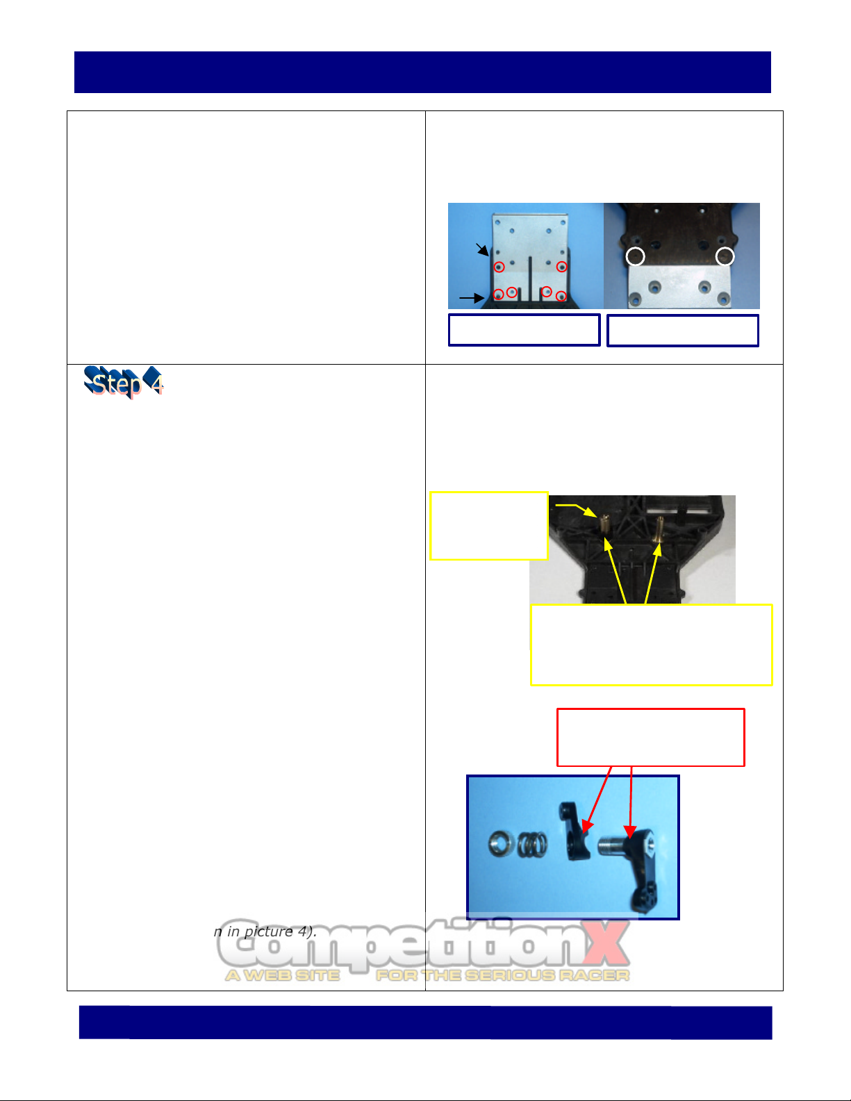
ØMount the Tie Bar part number DC-008
with the provided 4-40 x 3/8” Flat Head
screw over the RH steering crank. Need to
add a #4 washer between tie bar and bell
crank. (As shown in picture 4). Tightened
the screw all the way in, then back off
screw a 1/8 of a turn so that the tie bar
rotates freely.
ØInstall your steering links using the
turnbuckles and ball cups of your choice.
Each link should measure approx. 2.57”
(65 mm) in length from end to end. We
recommend you use a trapped end
cup/eyelet to attach servo link to the bell
crank. (More on that on step 7).
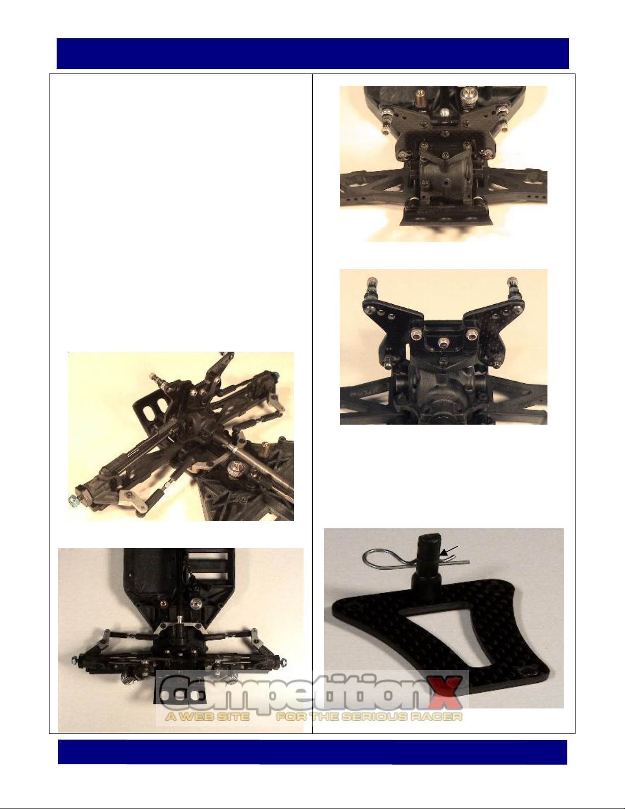
Assemble the Front Suspension:
ØMount the modified pivot blocks (part
number DC-016), starting with the
rearward first using the 2 supplied 4-40 x
½” Flat Head screws. Picture 5.
ØYou need to mount two 1/8” diameter
inner hinge pins. Insert the front A-Arms
(part number DC-013B) into the inner
hinge pin.
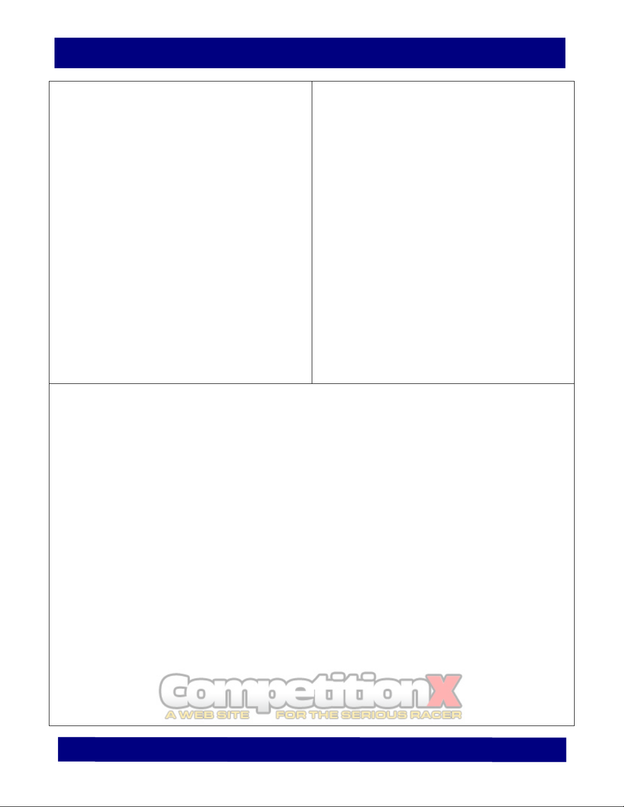
ØBe sure to modify and install a Rear
Bumper (Associated part number 3900) in
the front of the chassis as you assemble
the car. This bumper needs to be cut to
clear the gearbox. Also, the forward holes
must be elongated inboard to accept the
front arm mount which has a shorter span
length between the mounting holes. (See
the picture on the right).
ØMount the modified front bumper with the
modified forward front pivot block into the
inner hinge pin. Secure the pivot block
with the 2 provided 4-40 x ½” FH screws.
ØMount the assembled front differential
gearbox, and secure it with the 4 supplied
4-40 x ½” Flat Head screws. (Example
shown on picture 6).
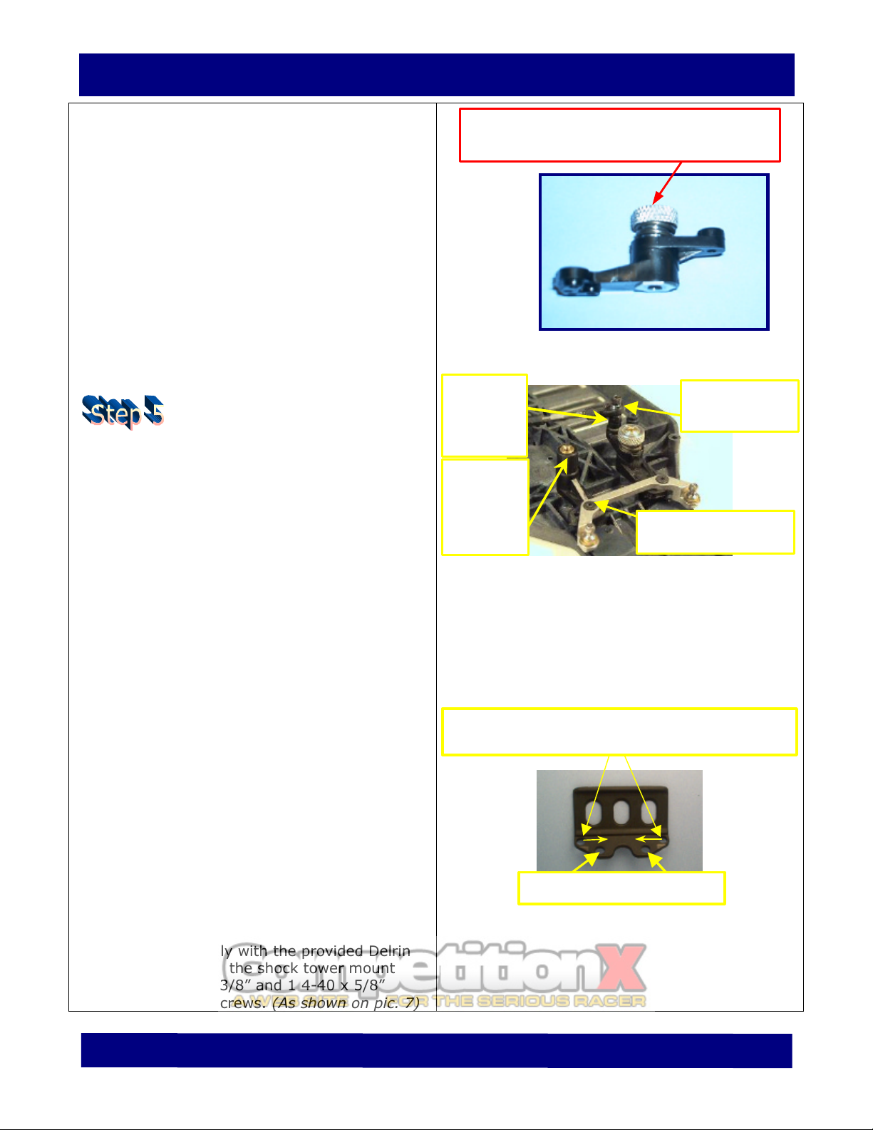
ØInstall the front shock tower mount to the
top of the transmission case. Shim the low
side accordingly with the provided Delrin
spacer. Secure the shock tower mount
with 3 4-40 x 3/8” and 1 4-40 x 5/8”
Socket Head screws. (As shown on pic. 7)
Picture 3
Picture 4: Tie Bar & Steering Bell Crank Installed
Tools required for this step:
Ø1/16” Allen Wrench or Driver
Ø3/32” Allen Wrench or Driver
ØDremmel tool
Elongate the two forward holes in the inboard
direction to fit front modified arm mount.
Eliminate Inner Holes
Install (0.30”)
long spacer
and secure
with 7/8”
long screw.
Install Tie Bar in
forward/inboard hole.
Install black
spacer DC-
007B on large
diameter
post.
Install trapped
end/eyelet cup
on this end.
Make sure that the upper surface of the
Aluminum nut is below the surface of the
threaded Aluminum post.

Page 9
TC3 “O” V2
RC Product Designs
ØInstall carbon fiber Front Shock Tower
(part number DC-002B) forward of the
Front Shock Tower Mount and secure with
3 lock nuts from behind the shock tower
mount. (Picture 8 & 9)
ØAssemble all 4 CVD according to the
instructions for the Associated TC3, but
using the kit MIP™ CVD bones part
number DC-012, to the stock Associated
TC3 axles. REMEMBER TO USE THE 4-
DEGREE FRONT BLOCK CARRIERS P/N:
3872).
ØIf you have purchased Aluminum Steering
knuckles, be sure to install them now.
ØInstall your Front camber links using the
turnbuckle and ball cups of your choice.
Each assemble link should measure
approx. 2.71” (69 mm) in length from end
to end. Final length will vary depending on
your camber settings. Mount link on the
lowest outboard hole of the shock tower
and on top of the steering knuckle.
ØOn the Steering Knuckles, mount the RH
and LH Steering Knuckle Extensions (Part
number DC-009B/010B) and secure them
with the 2 provided 4-40 x 3/8” Socket
Head screws. If installing Aluminum
Steering Knuckles then we recommend
applying a small amount of thread locking
compound, such as Lock-Tite, to the
threads of the screws. MAKE SURE THEY
ARE IN THE RIGHT POSITION, INSTALLED
FROM THE TOP. See Picture on the right.
(Optional: you can secure the screw with a
nut installed from the bottom as well).
ØInstall a ball stud on the steering knuckle
extension. Make sure you install on the
bottom of the extension, not from the top.
(We recommend you apply a small amount
of thread locking compound to the ball
stud threads prior to installation.)
ØInstall your front buggy shocks on the
outer holes of the Front Shock Tower
Picture 5: Complete Servo Saver (Bell-Crank
system) and Tie Bar Installed.
Picture 6: Gear box installed in the front end.
Picture 7: Shock tower mount installed.
Front Camber link measures approx. 2.75” (70 mm).
(For example turnbuckles of 1.97” (50 mm) in
length and standard 0.78” (20mm) long ball cups.
Use long screw 4-40 x 5/8” on the side
where you use the 0.2” Delrin spacer.

TC3 “O” V2
RC Product Designs
Page 10
Extension. To acquire proper clearance
between the shock and the tower
extension, you may need to shim the
plastic shock mount with washers. The
shocks must be mounted facing forward of
the shock tower. The lower shock mount
location should be the center hole in the
front A-Arm.
ØThe front body mount will need to be
installed in the center hole of the chassis
brace. You will need to secure it with one
4-40 x ½” flat head screw as shown in pic
13.
ØMount the Delrin Wheel Hex Adapters part
number DC-011B to the stock axles. Make
sure you have the pins inserted in the axle
prior to installation. The hex adapters
have been specifically designed to accept
the Schumacher Buggy Wheels.
Picture 10: Front End Assembly Rear View
Picture 11: Front End Assembly Top View
Picture 8: Front Shock Tower installed.
Picture 9: Front Tower Installed Rear View
ØInstall the front chassis brace DC-004B
with the supplied 0.10” spacers
underneath and the 4 4-40 x ½” socket
head screws as shown in Picture 14.
Picture 13: Carbon Fiber Chassis Brace
Front Body Mount

Page 11
TC3 “O” V2
RC Product Designs
Picture 12: Front End Assembly Front View Picture 14: Chassis Brace installed
Install Rear Suspension:
ØMount the modified pivot blocks (part
number DC-016), starting with the forward
block first using the 2 supplied 4-40 x ½”
Flat Head screws. Install the 1/8” diameter
inner hinge pins. Insert the rear A-Arms
(part number DC-014B) into the inner
hinge pin.
ØIf you wish to install (optional) the rear
bumper, then be sure to modify it prior to
its installation. This bumper needs to be
slightly modified to enhance the swing
clearance of the rear A-Arms. (Example
shown in the picture on the right).
ØIf you decided to use the rear bumper
then proceed to mount the modified
bumper with the modified rearward pivot
block into the inner hinge pin. Secure
them with the 2 provided 4-40 x ½” Flat
Head screws.
ØMount the new center drive shaft part
number DC-003B PRIOR to installing the
rear differential gearbox. Remember to
install the rubber “O” rings inside the drive
cups prior to installing the drive shaft.
ØMount the assembled rear differential
gearbox, and secure it with the 4 supplied
4-40 x ½” Flat Head screws. (Example
shown in the picture on the right).
Tools required for this step:
Ø0.16” & 3/32 “Allen Wrench or Driver
ØDremmel Cutting Wheel and 3/16” Nut
Driver
STOCK BUMPER
MODIFIED
w/Notched Corners
Install the (4) 0.1” Delrin spacers provided
underneath the chassis brace and secure the
brace with screws.
Bottom view of chassis with
modification. Rear bumper is
not shown.

TC3 “O” V2
RC Product Designs
Page 12
ØInstall the stock rear chassis braces to the
gearbox with the original screws.
ØInstall the Rear Shock Tower mount with
the 0.20” spacer using 3 4-40 x ½” Socket
Head screws and 1 4-40 x 5/8” socket
head screws on the hole that uses the
spacer.
ØInstall ball studs in the shock tower and
secure them with nuts. Install shock tower
to shock mount with the 2 supplied 4-40 x
1/2” button head screws and 1 4-40x3/8”
button head screw in the center of the
mount. Secure those with the Nylock Nuts
provided. (Example of installation can be
seen in picture on the right.)
ØInstall the wing mount kit DC-A4222 using
4 provided 4-40 x 3/8” socket head screws
on the rear shock tower. TIP: If you want
to increase rear down force, you can shim
the lower attachment point of the wing
mount with a small washer. This will
increase the angle of attack of the wing.
(Example of wing mount installed shown
below.)
ØInstall the rear CVD assemblies you
completed in previous steps, on the stock
rear hub carriers. Remember to use the
MIP™ CVD bones part number DC-012
with the stock Associated TC3 axles.
ØInstall your rear camber links using the
turnbuckle and ball cups of your choice.
Each assemble link should measure
approx. 3.05” (77 mm) in length from end
to end. Actual length will vary depending
on your camber settings. Mount link on the
furthest inboard hole in the rear hub
carrier and the upper inboard hole in the
shock tower. (Example camber link shown
Do not install a screw in this location (it
will be used for body mounts later on).

Page 13
TC3 “O” V2
RC Product Designs
in illustration below).
ØInstall your rear buggy shocks on the
second inboard hole in the rear shock
tower. To acquire proper clearance
between the shock and the tower, you
may need to shim with washers the shock
plastic mount. The shocks must be
mounted facing the rear of the car. It is
recommended to mount the shock in the
2nd outboard hole in the rear A-Arm.
Rear Camber link length measures approx. 3.05”
(77 mm). (We used turnbuckles of 1.57” (40 mm)
in length and 1”(25mm) long heavy duty ball cups.)

TC3 “O” V2
RC Product Designs
Page 14
Steering Servo Installation:
ØUse the Delrin servo mounts part number
DC-017B, with the appropriate Associated
spacers, based on your servo brand, to
install your servo first. (Please refer to the
Associated TC3 Instruction Manual). Make
sure you install the servo horn in this step
too. Try to use a long servo horn for
improved clearances to the drive shaft.
Secure the servo mounts from the bottom
of the chassis with the 2 supplied 4-40 x
3/8” Flat Head screws.
ØInstall your servo steering link using the
turnbuckle and ball cup/trapped eyelet of
your choice. The link should measure
approx. 2.76” (70 mm) in length from end
to end. Use the provided 0.3” spacer on
the backside of the bell crank to increase
clearance of the steering link to the
driveshaft. Use the needle nose pliers to
pop in the ball cups on the ball studs.
ØWhen adjusting the total steering throw of
the system, pay attention to the inboard
ball cups in the steering links so that they
do not touch the center drive cup.
Body Mount Installation:
ØWe recommend you use the Associated
“Front Body Mount” kit for all three
positions to support the body or you could
use the aftermarket Parma Body mount
kit. You can actually choose any kind you
want as long as you can adjust the height
of the body to your preference. The choice
is yours. (Example shown on next page
with Associated mounts).
ØWe have provided 4-40 threaded rod and
nuts, so you can create the assembly once
you pick the body mounts of your choice.
Tools required for this step:
ØNeedle Nose Pliers
Ø3/16” Nut Driver
Black Delrin Servo mount installed in
chassis.
Note: Servo not shown installed in
picture. Must install servo to mounts
first, then to install assembly to chassis.
Servo Steering link length measures approx.
2.76” (70 mm). We used a turnbuckle of 1.57”
(40 mm) in length and 1”(25mm) long heavy duty
ball cup in one end and a trapped eyelet in the
other.

Page 15
TC3 “O” V2
RC Product Designs
ØFirst insert the jam nuts on the threaded
rod, and double jam them in the middle of
the rod, leaving about ½” of thread to go
into the rear gearbox mount hole. The
upper portion of the rod you will use for
installing the body mount post. Thread the
post all the way down, flush with the 4-40
nuts as shown in the picture on the right.
Wheel Installation:
ØPrior to installing any wheel, make sure
you check the wheel for any excess
flashing left from the molding process on
the hex socket that may inhibit wheel
installation. BE SURE TO SEAT THE WHEEL
ON THE WHEEL ADAPTER COMPLETELY. IT
IS DESIGNED WITH TIGHT TOLERANCES
FOR A CLOSE FIT IN THE WHEEL.
Rear Body Mount

TC3 “O” V2
RC Product Designs
Page 16
TIPS:
ØTypical motor wind used in this car can
range from 8 turns all the way to 15 turn
motors. You can actually use higher motor
winds, the choice is up to you!
ØUsing the stock 72 spur gear, the following
pinion combinations can be expected for the
given motors as a good starting point:
Ø15 Turn Double – 19 Teeth Pinion
Ø14 Turn Double – 18 Teeth Pinion
Ø13 Turn Double – 18 Teeth Pinion
Ø12 Turn Double – 17 Teeth Pinion
Ø11 Turn Double – 17 Teeth Pinion
Ø10 Turn Double – 16 Teeth Pinion
Ø9 Turn Double - 16 Teeth Pinion
Ø8 Turn Double - 16 Teeth Pinion
ØBelow this….GOOD LUCK!
ØRemember, that if you change the spur
gear, the matching numbers shown above
may change as well.
ØThe largest spur gear we can fit, without
modifying the chassis is 80 teeth spur gear.
ØAfter every raceday we recommend that
you inspect the steering bell crank to the
brass posts surfaces. Clean the surfaces and
re-apply small amounts of suitable lubricant
(i.e. Teflon grease, Lithium grease or even
powder graphite) to keep the surfaces
lubricated. Failure to clean them on a regular
basis may inhibit the steering system to
operate smoothly.
ØWe recommend that when you fit the body
to the chassis, you add a couple of pieces of
Velcro along each side of the car so you can
closeout/seal better the body, and minimize
the amount of dirt it can get inside the car.
ØIf you wish to seal all the orifices on the
bottom of the chassis (i.e. motor vent hole,
battery slot openings, spur clearance slot
opening, etc) to keep dirt from coming in
through them, then we suggest that you
install a flexible sheet film on the bottom
exterior surface of the chassis. The
Associated chassis protection sheet film
works very well on this application. Make
sure you clean the bottom surface of the
chassis thoroughly prior to applying the
sheet film. If necessary, apply liberal
amounts of motor cleaner to a clean cloth
rag, and scrub the bottom surface of the
chasis. Allow to dry for a couple of minutes,
prior to installation.
Website Address: www.rcproductdesigns.com
Enjoy the TC3 “O” V2 kit!
Table of contents