EN
7
The FMS 1/12 Kübelwagen RC Model presents itself in Mid-term to take you back to the war-torn
era with its spectacular design.
We start with engine.The Boxer air-cooled engine serves as the core of the car, an engine used in
several later generations of classic cars and lasted 65 years in the Beetle, a saga that came to an
end when the last Beetle, number 21,529,464, rolled off the production line in Puebla, Mexico, on
July 30, 2003.
Initially the Typ82 used a 985cc engine, later upgraded to 1131cc, then gradually increased
displacement, and in the PPPPPPPPPP used a 1488cc engine, doubling the horsepower from the
very beginning. The cylinders of the horizontally opposed engine are distributed on both sides, a
130 motor in the right cylinder position, and another 130 motor reserved for the left side, which can
output twice as much power when applied to the PPPPP or PPPPPPPPPP platform. The engine
crankshaft flywheel is connected by a belt to drive the generator and the cooling fan as well. The
semi-circular fan fairing is a major feature, in which the airflow is distributed to the cylinders on
both sides. All is restored on the model, meaning you can observe the blades rotating through the
fan intake when the motor is running. The Kübelwagen has 4 forward gears and the maximum
speed of each gear respectively goes as 1st gear 18.4km/h; 2nd gear 32.4km/h; 3rd gear
54.2km/h; 4th gear 83.6km/h. The corresponding red line of gearshift tips is available on the
dashboard. On the model, we designed a 2-speed shift to simulate the speed of the 1st and 3rd
gears of the real car. The power crosses over from the top of the rear axle differential and then
returns to the rear axle. The model share the same structure as the real engine, with the benefit of
compactness, making it easy to switch between 4WD and RWD modes. This shift function is
perfectly reproduced on the model to provide more driving pleasure when driving off-road.
Then let’s move to chassis. The popular portal axle in today's crawler market has been in mass
production for barrel car as early as 82 years ago, from which wheelside reducer reduction ratio of
15:21 has learned a lot, making the barrel car chassis minimum ground clearance of 310mm,
dwarfing all modern off-road cars on the market today. On the real car, the front and rear wheel
speeds are balanced by increasing the front axle differential gear ratio while on the model we set
the door axle reduction ratio to 1:1 for common front and rear axle differentials.
Solid load-bearing chassis with stamped central ridge tube chassis and body bears high torsional
resistance. The central drive shaft and electrical wiring are hidden in the ridge tube. The one piece
injection model features the texture of metal stamping with plastic as location and size of each
reinforcement are restored according to the actual car. The front and rear wheels adopt
torsion-bar-springs independent suspension allowing long travel capability and little space
occupation. We use torsion springs instead of torsion bar springs to present the front and rear
suspension, Easy to disassemble and change tuning.
The car body, on which R&D team spend the most time where you can see the BBBBB horn and
headlights, NNNNN camouflage lights. The tires are the most common 5.25×16 in the barrel car.
The prototype was developed on the basis of the People's Car KdF-Wagen chassis, model Typ62,
with an air-cooled horizontally opposed four-cylinder engine and a rear-mounted rear-wheel drive
layout. Although only rear-wheel drive was available, a limited-slip differential from ZF was used,
greatly enhancing the ability to get out of trouble. The talented designer Dr. Ferdinand Porsche
then continued to improve on this basis, adding wheel-side reducers to build a portal rear axle, and
increasing the ground clearance of the chassis by 50mm to a staggering 310mm. In December
1939, two Typ82s rolled off the assembly line,underwent and successfully passed rigorous tests
in Kummersdorf and Eisenach, and received its official name Pkw.K1 Typ82. It later became the
most widely used and best-performing light off-road vehicle in the German army, and was loved
by front line and soldiers. In late 1942, the U.S. Army acquired a Type 82 Kubelwagen, which was
then tested at Aberdeen Proving Ground. Army automotive experts evaluated it as an excellent
driving performance and good handling car with four-wheel independent suspension and an LSD
limited slip differential on the rear axle, with off-road performance approaching that of a four-wheel
drive vehicle. The actual test concluded that the bucket car was not as good as the Willys in terms
of extrication in extreme terrain, but in most off-road conditions the Typ82 showed excellent driving
performance as Willys, and better on-road driving performance and comfort than the Willys.In
addition, the barrel weighs only 685kg and the 985cc engine can produce 23.5hp with half the fuel
consumption of the Willys. In other words, the Germans used 60% of the raw materials to obtain
tactical maneuverability close to that of the Americans. With no beams, a smooth chassis,
extremely low unit pressure after installing desert tires, and an air-cooled engine that required
even less water, the barrel car's off-road performance in the desert terrain of the North African
battlefield far exceeded that of a 4WD. Later in the war the Germans were losing, and the U.S.
Army had the opportunity to capture more intact Type82, and the barrel car's good performance
was so popular with the U.S. Army that soldiers were even willing to trade two Willys for one
Type82.
Type82 is rear-wheel drive, while Typ86 and Typ87 four-wheel drive, of which Typ86 is not
mass-produced as the off-road performance of the Typ82 has been so excellent that increased
performance four-wheel drive version brought was more than pay for itself considering the
strained strategic resources. Moreover,its complex structure is also not conducive to wartime
production on a large scale, not to mention the maintenance burden brought to the logistics units.
Therefore, the four-wheel drive structure was only used on the Typ87 and the amphibious
Typ128/166, which had to use four-wheel drive.
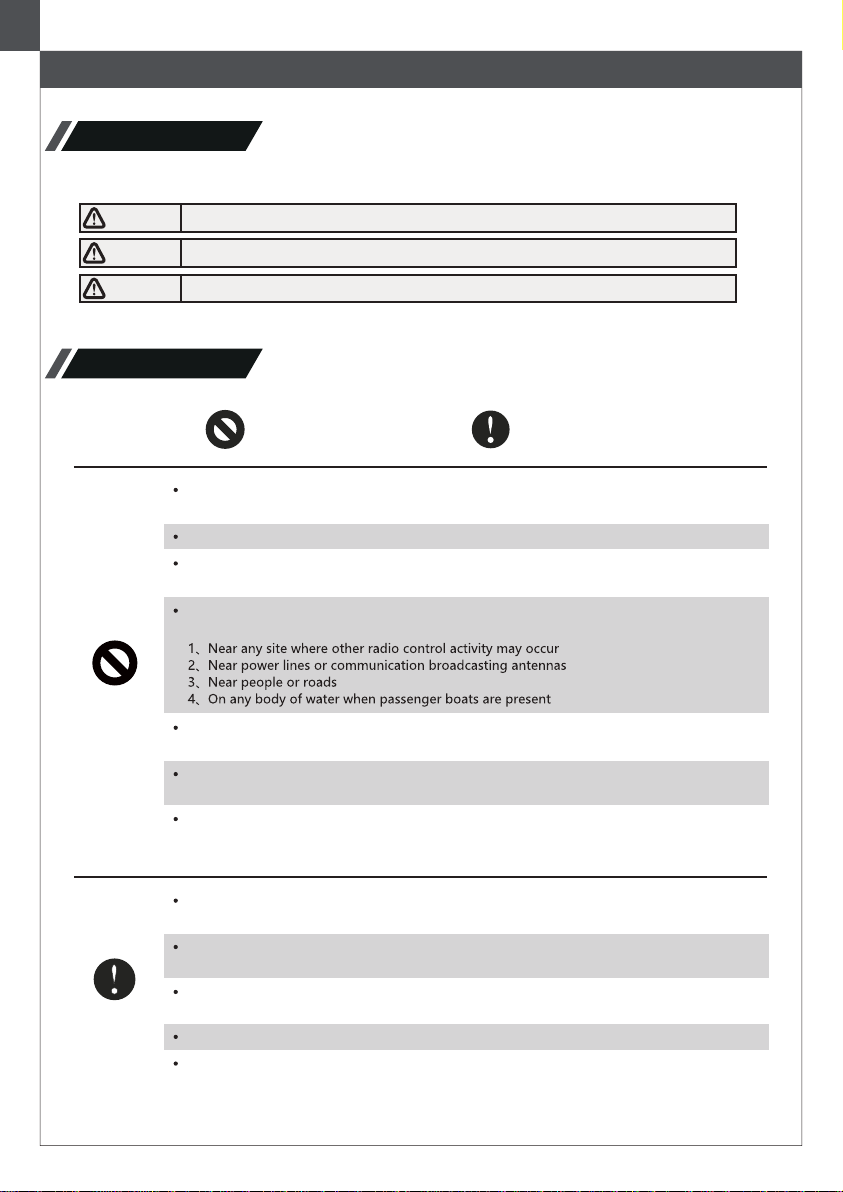
Like the real car, the simulated wheels need to be fixed with 5 screws, the spare tire on the front
available for being taken off and installed for use. Remove the spare tire, the typical of the mid-cy-
cle spare tire bracket is readily accessible. The windshield can be put down and fixed on the front
bracket and the real rearview mirror’s angle is adjustable like a real car.
The openable four doors are not worth mentioning but it would be much more interesting to find
the structure that the doors could be opened and locked by turning the door handle. The comfort-
able seats have soft foam cushions even a little bit luxurious by 1939 standards.
The dashboard shows the speed and timing of gear changes with the current mileage 203 km,
about the distance driven from the Wolfsburg factory to Berlin. No doubt we are selling a new car.
To start this car, it is hard to find the switch but the user guide of the real car is available for you to
find the start button in the lower left corner of the dashboard. Just press it through the steering
wheel.A sweet gadget is also provided for your convenience. As FMS always did, the steering
wheel and the wheel are linked. With 1/12 figures, a plot can be vividly displayed and users can
gradually refine the plot with the increase of this series.
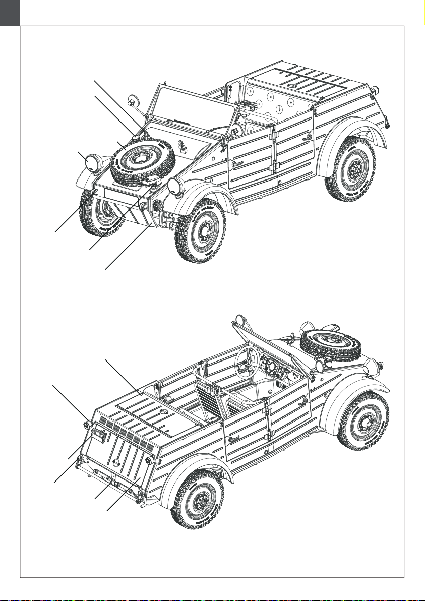
The armrest in front of the rear seats has four clips in the middle that fit into holes in the floor to
hold four 98K rifles which were produced by the Mauser Arsenal in Oberndorf and needed to be
purchased separately for 70 Reichsmark each at the 1939 exchange rate. The rear seatbacks
could be lowered for easy access to supplies from the trunk. Great efforts have been made on
optimizing the layout of the electronics to prevent the battery or receiver from taking up space in
the trunk. The trunk height of the Typ82 was designed to accommodate 20L oil (water) Jerry can
or to store weapons, ammunition, and food supplies. All these features are properly restored to
make the user experience more fun, but of course, these supplies, like the 98K, had to be
purchased separately.
For the electronic system, 4-channel digital proportional remote control system is applied. In
addition to 1&2 channels for steering and throttle control, the 3rd channel controls the gearshift
and the 4th channel switching between 4WD and RWD. There is also integrated light control,
which allows you to turn on the headlights during normal night driving. Linked turn signals and
brake lights are at the rear of the car. Users can only turn on the anti-aircraft lights during the night
light restriction.
Then comes to the packaging, which used environmental friendly foam material to simulate the
World War II German tin ammunition boxes. The recyclable box can bear long-distance transport
easy to store, easy to carry.
Kübelwagen has a far-reaching impact on automobile history. Many famous hobby brands have
repeatedly launched related products. So far, no one can do as well as us.
We here at FMS hope you enjoy the Kübelwagen Type 82 as much as we did in bringing it to life
in the form of this classic piece of wartime history.
Ty82 Research Team
2021.9.29
About Mode