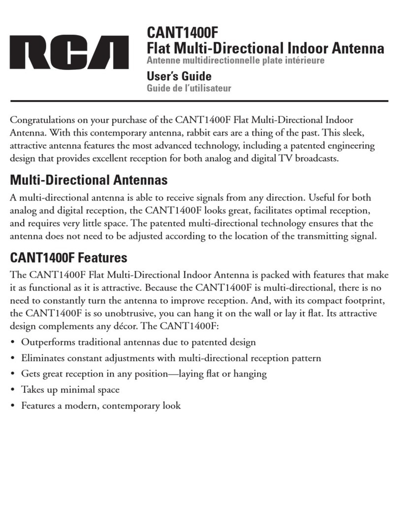
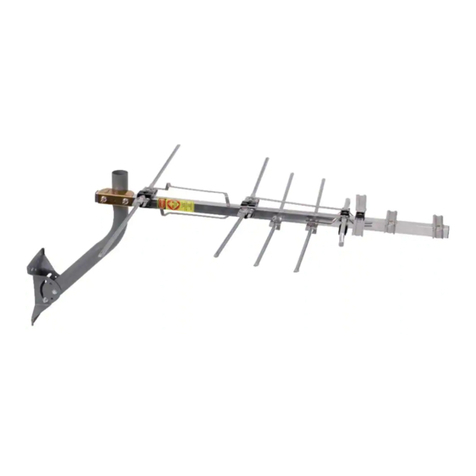
RCA ANT860E IB 01 User manual

1
Versión
en español
al dorso
AMPLIFIED
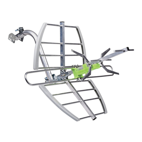
OUTDOOR/ATTIC HD ANTENNA
INSTALLATION GUIDE
ANT860E IB 01
BEFORE YOU START!!!
Please read the IMPORTANT SAFETY INFORMATION sheet included in this package.
Important!
If you don’t know where
your broadcast towers
are, download the “RCA
Signal Finder” App on
your smartphone and
follow the directions in
the App to nd the best
location and orientation
for your antenna.
Your antenna works
best when oriented
toward the TV
broadcast towers in
your area.
What’s in the package?
(1) Main element
(2) Long and (2) short VHF dipoles
(1) Mounting base
(4) 1/4”x20 wood screws (2) Clamps
(1) 16ft coaxial
cable
(1) Amplier insert
(1) Hardware bag
(4) Hex Nuts
ANTENNA
TV/STB
(4) Mounting anchors
(1) M5x19 screw
(2) U-bolts

2
A. Mount the base to a at surface.
Find the four wood screws included in this package. Using these screws,
attach the base to the surface as shown here.
Antenna, front
Long VHF dipole
Short VHF dipole
Connect the VHF dipoles to the antenna.
Mount the antenna
2
Insert the hollow end of each long dipole into the top holes on either side of the antenna. Once the hollow
end contacts the screw threads inside this hole, screw the dipole tightly into place.
Insert the hollow ends of two short dipoles into the bottom holes on either side of the antenna. Once the
hollow ends contact the screw threads inside these holes, screw the dipoles tightly into place.
Assemble the antenna
1
If you’re mounting to concrete, brick, or drywall...
You’ll need to use the anchors included in this package. Here’s how to
install them:
• Place the antenna base against the surface where you want to
mount the antenna. Make sure it’s level.
• Mark the surface through the holes in the base where you’re
going to mount the antenna.
• Set the base aside and use a 1/4” drill bit to drill pilot holes
at each marked location. Remove any excess dust from the
holes.
• Insert a concrete anchor into each hole so that it is ush with
the concrete surface. You can use a hammer to gently tap the
anchors into place if necessary.
• Place the antenna base back against the concrete surface
and secure it using the four wood screws provided. Do not
overtighten these screws.

3
WARNING: Never hang anything from this antenna; never attach foreign objects to this antenna.
NOTE: In most cases, this antenna provides the best performance when mounted outdoors in a high
location (such as on the roof or high up on the side of your house). This antenna can also be mounted in an
attic.
Antenna, back
B. Connect the antenna to the base.
Line up the round section at the bottom of the antenna with the round section on the mounting antenna.
Make sure the sides with the teeth are facing each other. Insert the M5x19 screw into the base as shown.
Screw it into the round section of the antenna to connect the antenna to the base.
Mounting to a mast (not included)
To adjust the antenna’s position: Loosen the M5x19 screw slightly and move the antenna to the desired
position. Then tighten the screw again.
1. If you’re using the provided coaxial cable, thread it through one of the U-bolts. Find the coaxial cable
and one of the U-bolts included in this package. Thread the coaxial cable through the U-bolt as shown
here. IMPORTANT: If you’re not using the coaxial cable that came with this antenna, skip step 1.
2. Attach the clamp assemblies to the base. Find the other U-bolt, the four hex nuts, the two clamps, and
the antenna base included in this package.
Insert each U-bolt into the base as shown here. Then position a clamp and two hex nuts on the end of
each U-bolt as shown here.
3. Mount the base to the mast (not included).
Slide the antenna clamp assembly over the mast, positioning the mast between the clamp and the
antenna base. Position the antenna base as high as possible on the mast. Orient the base in the
direction you want. Then tighten the clamps and hex nuts securely onto the mast.
4. Follow the directions at the top of this page for connecting the antenna to the base and adjusting it to
the desired position.
12
3

4
Connect one end of the included coaxial cable to
the F-connector on the back of the antenna (if
you need a longer length of cable, you can use
your own coaxial cable).
Once you’ve tightened the cable, lower the rain
boot over the connection to protect it from water.
Connect to your TV
3
F-connector
Rain boot
Coax
Cable
At the point where your coaxial cable lead enters the house, you should
allow for some slack in the coaxial cable as a “drip loop.” This will prevent
moisture from running down the coaxial cable and entering the house.
Run the coaxial cable approximately six inches below the wall entry
point and then turn it upwards towards this spot. Any moisture that
accumulates on the coaxial cable will drip off in the bend instead of
running into the house. You should seal the point where the cable
enters your home with a rubber weather insulator or silicone caulking
(not included). An “F” connector wall plate can be used inside the home
to cover the inside portion of the hole. You can typically nd an “F”
connector wall plate at any local electronics or hardware store.
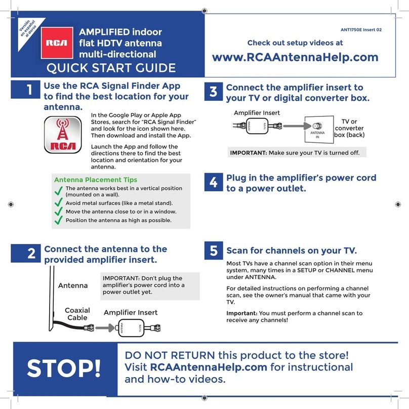
A. Connect the antenna to the coaxial cable.
B. Make a rain loop (for outdoor installations).

5
ANTENNA
IN
ANTENNA
TV/STB
Coax
Cable
Amplier Insert
Note: If you want to split the signal
coming from the antenna, connect
the short coaxial cable built into
the amplier insert to your splitter
(splitter sold separately). DO NOT
PUT THE SIGNAL SPLITTER BETWEEN
THE AMPLIFIER INSERT AND THE
ANTENNA.
ANTENNA
TV/STB
After all other connections are made, plug the power
amplier’s power cable into a standard AC outlet.
Important: This power adapter should be plugged in so
that it stays vertical or lays at.
The amplier insert should always be located indoors.
C. Connect the coaxial cable to the amplier.
TV
D. Plug in the power amplier.
Connect the coaxial cable coming from the antenna to the ANTENNA jack
on the supplied amplier insert.
Connect the built-in coaxial cable on the other side of the amplier insert
to the antenna input jack on your TV or converter box.

6
Most TVs have a channel scan option in their menu system, many times in a SETUP or CHANNEL menu
under ANTENNA. For detailed instructions on performing a channel scan, see the owner’s manual that came
with your TV.
Note: If you move the switch on the amplier or change the position of the antenna, you should scan for
channels again.
FCC Statement
This device complies with part 15 of the FCC Rules. Operation is subject to the following two conditions: (1) This device may not cause
harmful interference, and (2) this device must accept any interference received, including interference that may cause undesired
operation.
This equipment has been tested and found to comply with the limits for a Class B Digital Device, pursuant to Part 15 of the FCC Rules.
These limits are designed to provide reasonable protection against harmful interference in a residential installation. This equipment
generates, uses and can radiate radio frequency energy and, if not installed and used in accordance with the instructions, may
cause harmful interference to radio communications. However, there is no guarantee that interference will not occur in a particular
installation. If this equipment does cause harmful interference to radio or television reception, which can be determined by turning
the radio or television off and on, the user is encouraged to try to correct interference by one or more of the following measures:
• Reorient or relocate the receiving antenna.
• Increase the separation between the equipment and receiver.
• Connect the equipment into an outlet on another circuit.
• Consult the dealer or an experienced radio/TV technician for help.
Caution: Any changes or modifications not expressly approved by the party responsible for compliance could void the user’s authority
to operate this equipment.
Industry Canada Regulatory Information
CAN ICES-3 (B)/NMB-3 (B)
Avis d’Industrie Canada
CAN ICES-3 (B)/NMB-3 (B)
Scan for channels on your TV
4
MENU
Setup
Channel
Language
Channel Search...
12 Month Limited Warranty
Voxx Accessories Corporation (the “Company”) warrants to the original retail purchaser of this product that should this product or any
part thereof, under normal use and conditions, be proven defective in material or workmanship within 12 months from the date of
original purchase, such defect(s) will be repaired or replaced with new or reconditioned product (at the Company’s option) without
charge for parts and repair labor. To obtain repair or replacement within the terms of the warranty, the product is to be delivered with
proof of warranty coverage (e.g. dated bill of sale), specication of defect(s), transportation prepaid, to an approved warranty station.
For the location of the nearest warranty station to you, call toll-free to our control ofce: 1-800-645-4994.
This Warranty is not transferable and does not cover product purchased, serviced or used outside the United States or Canada. The
Warranty does not extend to the elimination of externally generated static or noise. This Warranty does not apply to costs incurred for
installation, removal or reinstallation of the product, or, if in the Company’s opinion, the product has been damaged through acts of
nature, alteration, improper installation, mishandling, misuse, neglect, or accident. This Warranty does not cover damage caused by an
AC adapter not provided with the product.
THE EXTENT OF THE COMPANY’S LIABILITY UNDER THIS WARRANTY IS LIMITED TO THE REPAIR OR REPLACEMENT PROVIDED ABOVE
AND, IN NO EVENT, SHALL THE COMPANY’S LIABILITY EXCEED THE PURCHASE PRICE PAID BY PURCHASER FOR THE PRODUCT. This
Warranty is in lieu of all other express warranties or liabilities. ANY IMPLIED WARRANTIES, INCLUDING ANY IMPLIED WARRANTY OF
MERCHANTABILITY OR FITNESS FOR A PARTICULAR PURPOSE, SHALL BE LIMITED TO DURATION OF THIS WARRANTY. ANY ACTION
FOR BREACH OF ANY WARRANTY HEREUNDER, INCLUDING ANY IMPLIED WARRANTY, MUST BE BROUGHT WITHIN A PERIOD OF 24
MONTHS FROM THE DATE OF ORIGINAL PURCHASE. IN NO CASE SHALL THE COMPANY BE LIABLE FOR ANY CONSEQUENTIAL OR
INCIDENTAL DAMAGES WHATSOEVER. No person or representative is authorized to assume for the Company any liability other than
expressed herein in connection with the sale of this product.
Some states/provinces do not allow limitations on how long an implied warranty lasts or the exclusion or limitation of incidental or
consequential damage so the above limitations or exclusions may not apply to you. This Warranty gives you specic legal rights and
you may also have other rights which vary from state/province to state/province.

6
La mayoría de los televisores cuentan con una función de búsqueda en el sistema de menús, muchas veces
en el menú CONFIGURACIÓN O CANAL, dentro de ANTENA. Para obtener instrucciones detalladas sobre
cómo realizar una búsqueda de canales, consulte el manual del propietario incluido con el televisor.
Nota: Si mueve el interruptor del amplicador o cambia la posición de la antena, deberá volver a realizar la
búsqueda de canales.
Declaración de la FCC
Este dispositivo cumple con el Apartado 15 de las Reglas de la FCC. El funcionamiento está sujeto a las siguientes dos condiciones:
(1) Este dispositivo no provocará una interferencia perjudicial y (2) este dispositivo deberá aceptar cualquier interferencia recibida,
incluida una interferencia que podría provocar un funcionamiento no deseado.
Este equipo se sometió a pruebas y se determinó que cumple con los límites de un dispositivo digital Clase “B”, de conformidad
con el Apartado 15 de las Reglas de la FCC. Estos límites están diseñados para proporcionar una protección razonable frente a
interferencia perjudicial cuando se utiliza el equipo en un entorno residencial. Este equipo genera, utiliza y puede irradiar energía
de radiofrecuencia y, si no se lo instala y utiliza de acuerdo con el de instrucciones, puede provocar una interferencia perjudicial en
las comunicaciones radiales. Sin embargo, no existe ninguna garantía de que esta interferencia no ocurrirá en una instalación en
particular. Si este equipo provoca una interferencia dañina con la recepción de radio o TV, la que puede determinarse encendiendo y
apagando el equipo, se recomienda al usuario que intente corregir la interferencia tomando una de las siguientes medidas:
• Reoriente o reubique la antena receptora.
• Aumente la separación entre el equipo y el receptor.
• Conecte el equipo a un tomacorriente ubicado en un circuito diferente de aquel al que está conectado el receptor.
• Consulte al distribuidor o un técnico de radio/TV experimentado para obtener ayuda.
Precaución: Cualquier cambio o modificación no aprobados de forma explícita por la parte responsable del cumplimiento podría
anular la autoridad del usuario de utilizar este equipo.
Información regulatoria de Industry Canada
CAN ICES-3 (B)/NMB-3 (B)
Búsqueda de canales en el televisor
4
MENU
Setup
Channel
Language
Channel Search...
Garantía Limitada de 12 Meses
Voxx Accessories Corporation (la “Compañía”) le garantiza a usted, el comprador original de este producto que si, bajo condiciones y
uso normales, se encontrara que este producto o alguna pieza presenta defectos materiales o de mano de obra dentro de los primeros
12 meses a partir de la fecha de compra original, tales defectos serán reparados o reemplazados con un producto nuevo o renovado (a
opción de la Compañía) sin cargo alguno por las piezas y labores de reparación. Para obtener los servicios de reparación o reemplazo
dentro de los términos de esta garantía, el producto se entregará con prueba de cubierta de garantía (por ejemplo, factura fechada de
venta), especicación de los defectos, transporte prepagado, a una estación de garantía aprobada. Para ubicar la estación de garantía
más cercana a su domicilio, llame sin costo a nuestra ocina de control:
al 1-800-645-4994.
Esta Garantía no es transferible y no cubre un producto adquirido, mantenido o utilizado fuera de los Estados Unidos o Canadá. Esta
Garantía no incluye la eliminación de estática o ruido generados externamente. Esta Garantía no incluye los costos incurridos en la
instalación, remoción o reinstalación de este producto, o, si es opinión de la Compañía, que este producto ha sufrido daños debido a
causas de fuerza mayor, alteraciones, instalación inadecuada, abuso, uso indebido, negligencia o accidente. Esta Garantía no incluye
daños ocasionados por un adaptador de CA que no haya sido suministrado con el producto.
EL ALCANCE DE LA RESPONSABILIDAD DE LA COMPAÑÍA BAJO ESTA GARANTÍA ESTÁ LIMITADO A LA REPARACIÓN O EL
REEMPLAZO PROVISTO ARRIBA Y, EN NINGÚN CASO, DEBERÁ LA RESPONSABILIDAD DE LA COMPAÑÍA EXCEDER EL PRECIO DE
COMPRA PAGADO POR EL COMPRADOR DE ESTE PRODUCTO. Esta Garantía reemplaza cualesquiera otras responsabilidades o
garantías expresas. CUALESQUIERA GARANTÍAS IMPLÍCITAS, INCLUYENDO CUALQUIER GARANTÍA IMPLÍCITA DE COMERCIABILIDAD
O ADAPTABILIDAD PARA UN PROPÓSITO EN PARTICULAR ESTARÁN LIMITADAS A LA DURACIÓN DE ESTA GARANTÍA. CUALQUIER
ACCIÓN PARA EL INCUMPLIMIENTO DE CUALQUIER GARANTÍA EN EL PRESENTE, INCLUYENDO CUALQUIER GARANTÍA IMPLÍCITA,
DEBERÁ PRESENTARSE DENTRO DE UN PERÍODO DE 24 MESES A PARTIR DE LA FECHA DE COMPRA ORIGINAL. EN NINGÚN CASO LA
COMPAÑÍA SERÁ RESPONSABLE POR DAÑOS EMERGENTES O INCIDENTALES. Ninguna persona ni representante está autorizado a
asumir, a nombre de la Compañía, ninguna responsabilidad salvo la expresada aquí en conexión con la venta de este producto.
Algunos estados/provincias no permiten limitaciones sobre la duración de una garantía implícita o la exclusión o la limitación de daños
incidentales o emergentes, de modo que es posible que las limitaciones o exclusiones anteriores no apliquen en su caso. Esta Garantía
le conere derechos legales especícos; según el estado/provincia, puede disfrutar además de otros derechos.

5
ANTENNA
IN
ANTENNA
TV/STB
Cable
coaxial
Inserto para amplicador
Nota: Si desea dividir la señal
proveniente de la antena, conecte
el cable coaxial corto integrado
en el inserto para amplicador en
el divisor (el divisor se vende por
separado). NO COLOQUE EL DIVISOR
DE SEÑAL ENTRE EL INSERTO PARA
AMPLIFICADOR Y LA ANTENA.
ANTENNA
TV/STB
Después de que se realicen todas las otras conexiones,
enchufe el cable de alimentación del amplicador de
potencia en un tomacorriente de CA estándar.
Importante: Este adaptador de alimentación deberá
estar enchufado de forma tal que permanezca en
posición vertical o apoyado de forma plana.
El inserto para amplicador deberá estar siempre
ubicado en interiores.
C. Conecte el cable coaxial al amplicador.
TV
D. Enchufe el amplicador de potencia.
Conecte el cable coaxial proveniente de la antena al conector ANTENNA
ubicado en el inserto para amplicador suministrado.
Conecte el cable coaxial integrado que está ubicado en el otro lado del
inserto para amplicador en el conector de entrada de antena en el
televisor o caja convertidora.

4
Conecte un extremo del cable coaxial incluido al
conector “F” ubicado en la parte posterior de la
antena (si necesita una longitud del cable más
extensa, puede utilizar su propio cable coaxial).
Una vez que haya apretado el cable, coloque la
cubierta antilluvia en la conexión para protegerla
de agua.
Conexión con el televisor
3
Conector “F”
Cubierta
antilluvia
Cable
coaxial
A. Conecte la antena al cable coaxial.
B. Realice un bucle para lluvia (en el caso de instalaciones
en exteriores).
En el punto donde el terminal del cable ingresa en el hogar, deberá
permitir cierta holgura del cable coaxial para realizar un “bucle para
goteo”. Esto evitará que la humedad se acumule en el cable coaxial e
ingrese al hogar.
Coloque el cable coaxial aproximadamente 6 pulgadas por debajo del
punto de entrada por la pared y luego gírelo hacia arriba hacia este punto.
Cualquier humedad que se acumule en el cable coaxial goteará y caerá
al llegar al bucle en lugar de ingresar al hogar. Deberá sellar el punto
donde el cable ingresa al hogar con un aislante resistente al clima de
goma o con silicona (no incluidos). Se puede utilizar una placa de pared
con conector “F” dentro del hogar para cubrir la parte interior del oricio.
Generalmente, puede encontrar una placa de pared con conector “F” en
cualquier tienda de electrónica o ferretería local.

3
Antena, parte posterior
B. Conecte la antena a la base.
Alinee la sección redonda ubicada en la parte inferior de la antena con la sección redonda ubicada en la
antena de montaje. Asegúrese de que los lados con los dientes queden apuntando entre sí. Inserte el tornillo
M5x19 en la base, tal como se muestra. Atorníllelo a la sección redonda de la antena para conectar la antena
a la base.
Instalación en un mástil (no incluido)
Para ajustar la posición de la antena: aoje ligeramente el tornillo M5x19 y mueva la antena a la posición
deseada. A continuación, vuelva a apretar el tornillo.
1. Si está utilizando el cable coaxial proporcionado, páselo por uno de los pernos en “U”. Busque el cable
coaxial y uno de los pernos en “U” incluidos en el embalaje. Pase el cable coaxial por el perno en “U” como se
muestra aquí. IMPORTANTE: Si no está utilizando el cable coaxial incluido con esta antena, omita el paso 1.
2. Enganches los conjuntos de abrazaderas a la base. Busque el otro perno en “U”, las cuatro tuercas
hexagonales, las dos abrazaderas y la base de la antena incluidas en el embalaje.
Inserte cada perno en “U” en la base, tal como se muestra aquí. A continuación, coloque una abrazadera y
las dos tuercas hexagonales en el extremo de cada perno en “U”, tal como se muestra aquí.
3. Coloque la base en el mástil (no incluido).
Deslice el conjunto de la abrazadera de la antena por sobre el mástil, colocando el mástil entre la
abrazadera y la base de la antena. Coloque la antena lo más alto posible en el mástil. Oriente la base hacia
la dirección deseada. A continuación, apriete la abrazaderas y las tuercas hexagonales de forma segura al
mástil.
4. Siga las instrucciones que aparecen en la parte superior de esta página para conectar la antena a la base y
ajustarla en la posición deseada.
12
3
ADVERTENCIA: Nunca cuelgue ningún elemento de esta antena; nunca sujete objetos extraños a esta
antena.
NOTA: En la mayoría de los casos, esta antena proporciona el mejor rendimiento cuando se la instala en
exteriores en una ubicación elevada (como en el techo o en lo alto junto a su hogar). Esta antena también
puede instalarse en un ático.

2
A. Coloque la base en una supercie plana.
Busque los 4 tornillos para madera incluidos en el embalaje. Con estos
tornillos, sujete la base a la supercie, tal como se muestra aquí.
Antena,
parte frontal
Dipolo VHF largo
Conecte los dipolos VHF a la antena.
Realice el montaje de la antena
2
Inserte el extremo hueco de cada dipolo largo en los oricios superiores ubicados en ambos lados de la
antena.
Una vez que el extremo hueco entre en contacto con las roscas de tornillo del interior de este
oricio, atornille el dipolo de forma rme en su lugar.
Inserte el extremo hueco de cada dipolo corto en los oricios inferiores ubicados a ambos lados de la
antena.
Una vez que los extremos huecos entren en contacto con las roscas de tornillo del interior de estos
oricios, atornille los dipolos de forma rme en su lugar.
Si realizará el montaje en hormigón, ladrillo o placa de yeso:
Deberá utilizar los tacos incluidos en el embalaje. A continuación, se
detalla cómo colocarlos:
• Coloque la base de la antena contra la supercie en la que
desea instalar la antena. Asegúrese de que esté nivelada.
• Marque los oricios de la base en la supercie que desea
instalar la antena.
• Coloque la base a un lado y utilice una broca de 1/4” para
perforar oricios guía en cada ubicación marcada. Extraiga el
exceso de polvo de los oricios.
• Inserte un taco para hormigón en cada oricio de forma tal que
quede al ras de la supercie de hormigón. Puede utilizar para
introducir ligeramente los tacos en la placa, de ser necesario.
• Coloque la base de la antena contra la supercie de hormigón
y asegúrela con los cuatro tornillos suministrados. No apriete
los tornillos en exceso.
Ensamble la antena
1
Dipolo VHF corto

1
English
version
on back
ANTENA HD AMPLIFICADA
PARA EXTERIORES/ÁTICOS
GUÍA DE INSTALACIÓN
ANT860E IB 01
¡Importante! Si desconoce dónde
se encuentran las
torres de transmisión,
descargue la aplicación
“RCA Signal Finder” en
su teléfono inteligente
y siga las instrucciones
en la aplicación para
encontrar la mejor
ubicación y orientación
para su antena.
La antena funciona de
forma más eciente
cuando se la orienta
hacia las torres de
transmisión de TV de
su área.
¿Qué se incluye en el embalaje?
(2) Dipolos VHF largos y (2) cortos
(4) Tornillos para madera
de 1/4”x20
(1) Bola de tornillería
ANTENNA
TV/STB
(4) Tacos de montaje
(1) Tornillo M5x19
(2) Pernos en “U”
(2) Abrazaderas
¡ANTES DE COMENZAR!
Lea la hoja INFORMACIÓN IMPORTANTE DE SEGURIDAD incluida en el embalaje del producto.
(4) Tuercas hexagonales
(1) Elemento de antena principal (1) Base de montaje (1) Cable coaxial
de 16 pies
(1) Inserto para
amplicador
Table of contents
Other RCA Antenna manuals

RCA
RCA ANT752 User manual

RCA
RCA ANT501 - TV / Radio Antenna User manual

RCA
RCA ANT1268E User manual

RCA
RCA ANT1500 User manual

RCA
RCA ANT751 - Outdoor Antenna Optimized User manual

RCA
RCA ANT705Z User manual

RCA
RCA ANT3038XR User manual

RCA
RCA ANT1400R Use and maintenance manual

RCA
RCA ANT800 - HDTV Antenna - Outdoor User manual

RCA
RCA ANT1400E User manual
Popular Antenna manuals by other brands

SCAN-LINK
SCAN-LINK SLAU-UV-NB-04 user manual

UEC
UEC HALO manual

Abel & Profit
Abel & Profit MFJ-17754 instruction manual

Sea Tel
Sea Tel ST144-21 Installation and operation manual

Antennas Direct
Antennas Direct C2MVJ Quick start assembly/installation instructions

CUSHCRAFT
CUSHCRAFT LFA-2M16EL instruction manual