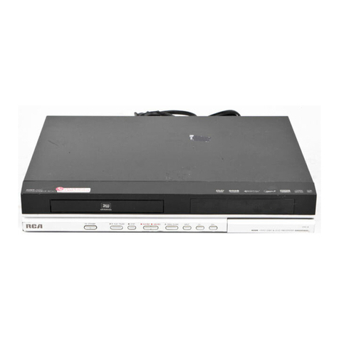
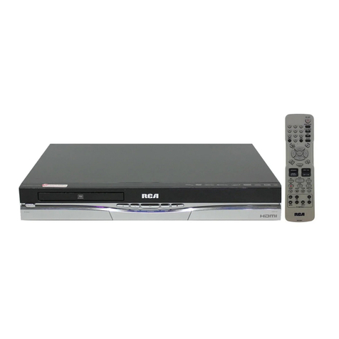
RCA DRC8052NB User manual

DVD Recorder
User's Guide
Changing am.

l+++@P++++++
This symbol indicates that this product incorporates double
insulation between hazardous mains voltage and user
[_--_ accessible parts¸
"Ihis symbol indicates "dangerous
vokage" inside the product that
presents a risk of elecuic sho& or
petsonal hljur>
rIhis symbol indicates
important into uctions
accompanying the product.
FCC INFORMATION
This equipment has been tested and found to comply with the limitsfor a Class B digital device.
pursuant to Part IS of the FCC rules+Theselimitsare designed to provide reasonable protection
againstharmful interference in a residential installation,Thisequipment generates, uses and can radiate
!_diofrequencyenergy and, if not installed and used inaccordance with the instructions,may cause
harmful interferenceto radio communications However;there is no guarantee that interference
will not occur in a particular installation. If this equipment does cause harmful interference to Imdio
or television reception, which can be determined by turning the equipment offand on. the user is
encouraged to try to corpect the interference by one or more of the followingmeasures
• Reorient or relocate the receiving antenna.
• Increase the separation between tile equipment and receiven
• Connect this equipment into an oudet on a circuit different from that to which the receiver is
connected.
• Consult the dealer or an experienced radio/TV technician for help.
This classBdigitalapparatus meets allrequirements ofthe Canadian Interference - Causing Equipment
Regulations.This class Bdigital apparatus complies with Canadian CES-003.
Cet appareil num4rique de la classBest conforme a lanorme du NHB-003 du Canada.
Refer to the identification/rating label located on the bad<panel of your product for its proper
operating voltage.
Product Registration
Please fill out the product legistration cald and return it immediately. Returning the product registration
card allows us to contact you if needed.
Keep your sales receipt to obtain warranty parts and service and for proof of purchase.Attach it here and
record the serial and model numbers in case you need them.The numbers are located on the bad<of the
DVD Recordel:
Hodel No+
PurchaseDate:
Serial No.
Dealer]AddresdPhone:
WARNING
To reduce the risk of fire or shock hazard, do not expose
this DVD Recorder to rain or moisture.
CAUTION
THISPRODUCTUTILIZESALASER.USEOF
CONTROLSORADJUSTHENTSOR PERFORHANCE
OFPROCEDURESOTHERTHANTHOSE SPECIFIED
HEREINHAY RESULTIN HAZARDOUS RADIATION
EXPOSUREDO NOT OPENCOVERSAND DO NOT
REPAIRYOURSELEREFERSERVICINGTOQUALIFIED
PERSONNEL
CAUTION
FCC Regulations state that unauthorized changes or
modifications to this equipment may void the user's
authority m operate it.
Note:
This DVD Recorder is designed and manufactured to
respond to the Region Hanagement Information. Ifthe
Region number of a DVD disc does not correspond to the
Region number of this DVD Recorder this DVDRecorder
cannot playthe disc.The Region number for this DVD
Recorder isRegion No I.
Note:
This device is protected byU.S.patent numbers 4.631,603
and 4,577,216 and 4,819.098 and other intellectual property
rights.The use of Macrovision's copy protection technology
in the device must be authorized by Hacrovision and is
intended for home and other limited pay-per-viewuses only.
unless otherwise authorized in writing by Hacrovision
Reverse engineering or disassembly is prohibited.
The apparatus shall not be exposed to dripping or splashing
and that no objects filled with liquids,such as vases,shallbe
placed on the apparatus.
IMPORTANT: The power cord can be
unplugged to turn off the main power to the
unit, It should also be easily accessible in an
emergency.
Ventilation:
Youmust adequately ventilate the product. Hake sine thepe is adequate space around the DVD
Recorder to provide proper air flow for ventilation See diagram.
I+he AC power cord is polarized (cme blade is wider than the other) and
only fits into AC oudets one wa> If the plug won't go into the outlet
completdy, rain the plug over and try to insert it the other wa): If it
still won't I_t. contact a qualified electrician to change the oudet or use a
dirks'rent one+ Do not attempt to bypass this safety feature. CLASS1 1
LASER
PRODUCT

Talbl of Cont÷n s
Types of Discs...................................................................2
Things to consider before you connect .......................... 2
Unpack the Box ................................................................ 3
Choose Your Connection ................................................. 4
Explanation of Input Jacks and Cables ........................... 5
Back of the DVD Recorder ............................................... 6
Explanation of Jacks .................................................. 6
Front of the DVD Recorder .............................................. 7
Connection: DVD recorder + TV ...................................... 9
Connection: DVD recorder + TV + Basic Cable Box ...... 11
Connection: DVD recorder + TV + Satellite Receiver... 13
Connection: DVD recorder + TV + Basic Cable Box
+Audio Receiver ............................................................. 15
Install Batteries in the Remote ...................................... 17
Point the Remote in the Right Direction ................ 17
Turn on the TV and DVD recorder ................................. 17
Complete the Initial Setup ............................................ 17
Setting the Clock ............................................................ 18
Setting the Date ...................................................... 18
Setting the Time Format (12 or 24 hour) ............... 18
Searching for Channels ........................................... 18
What to Expect ............................................................... 19
Turn on the DVD recorder to Watch TV ................. 19
Discs for Recording .................................................. 19
Next Steps ...................................................................... 20
Explanation of the Remote Control Buttons ............... 21
Button Descriptions for TV ............................................ 22
TV Controls ............................................................... 22
Using the Remote's Features ......................................... 22
Understanding the INPUT button ........................... 22
The Channel Banner ....................................................... 22
DVD Recording ............................................................... 23
DISCS THAT YOU CAN USE FOR RECORDING ......... 23
Express Recording .................................................... 23
Timer Recordings ........................................................... 23
Setting Up a Timer Recording ................................. 23
Watching one channel while you record another channel
(cable with no cable box or off-air antenna only) ...... 24
Recording from a DV Camcorder .................................. 24
Recording from a VCR.................................................... 24
DVD Playback ................................................................. 25
Editing DVD Discs ........................................................... 25
Recording Over Deleted Titles with Smart Record ...... 25
Regional Coding ............................................................. 26
Types of discs you can play ........................................... 26
How to Load and Play Discs .......................................... 26
Using Different Menus .................................................. 27
Search Options ............................................................... 27
Playback options ............................................................ 27
Using the On-screen Info Display ................................. 28
Playing Discs You Recorded (DVD+R and DVD+RW) ... 28
Playing mp3, WMA, JPEG, or DivX files ........................ 28
Creating an rap3 Disc on Your Computer .............. 29
The DVD Player Menu System ...................................... 30
General Menu .......................................................... 30
Language ........................................................... 30
Rating ................................................................. 30
Clock ................................................................... 31
Recording ........................................................... 31
DivX DRM ........................................................... 32
Version ............................................................... 32
Restore ............................................................... 32
AA/Output Menu (AudioNideo Output) ............... 33
Video .................................................................. 33
Audio ................................................................. 34
TV Channel Menu .................................................... 34
Auto Scan ........................................................... 34
Schedule Menu (Timer Recording) ......................... 34
Erase Disc ........................................................... 35
Finalize ............................................................... 35
Edit Disc Name ................................................... 35
Troubleshooting ............................................................. 36
Handling Cautions ......................................................... 39
Maintenance of Cabinet ................................................ 39
Limited Warranty ........................................................... 40
Accessory Information ................................................... 42
Graphics contained within this publication are for representation only 1

C@nnec ÷ns Se u E
._' DIGITAL
Types of Discs
DISCS YOU CAN USE FOR RECORDING
DVD_+R2.4x, 4x, or 8x, and 16x ONLY;
DVD_+RW 2.4x and 4x ONLY,
IMPORTANT? It is NOT possible to record content that is copy-protected. This is usually true for most pre-
recorded DVD discs and most pre-recorded VHS tapes,
Some discs may not
be compatible due to
laser pickup and disc
design.
TYPES OF DISCS YOU CAN PLAY
DVD discs - DVD movie discs (DVD ROM); DVD+R; DVD+RW: DVDRW (must be lecorded using vkteo mode
ol \"hi); DVD-}{ (must be recorded using video mode o_ VM and must be fin tlized). DVD audio discs are not
compadble.
CDs (Audio CDs, CD-R, CD-RW, DivX discs, rap3 discs) - Audio CDs contain musical ol sound content only: rap3
discsa_eCDs (CDR ol CDRW) d_at contain rap3 files. DivX discscontain Di_X files. This p_oduct alsoplays CDs
that contain JPEG and Whlk files ,rod Multisession CDs.
Video CD (VCD) - Like DVD _ideo discs, VCDs contain pictule md sound content. The difference is the amount
of inform _tion dHt cm be sto_ed on the disc. VCDs typicall) hwe lower pictme and sound qu _lity dam DVD discs.
You must use DV[)±R ot DV[:)±R_4 _discs to retold on your DVD recorder not VCDs.
Things to consider before you connect
Protect components from overheating
[)on't block ventilation holes on any of"the components. Aiiang_' rhc components so dlat ah" can cilculate fred).
Don't stack components.
_4q3en ?x)u place components in a stand, make smc you allow adequate" ventilation.
ffyou connect an audio rcceiw'r ol amplifi_'r, placeit on the top shelf.
Position cables properly to avoid audio interference
Ins_It each ctbl," filmly into th, "design ttcd jack.
If you place components above the-iV, rotate all cables down the side of the back of die TV instead ofsn'aight down the middle of the back of the
2Graphics contained within this publication are for e-epresenration only

Ch_p_er 1:_C@_nect_÷ns _nd S÷_u_
Connection Pictures
Audio/video cablvs ale ustlally bundl_'d togeth_'i. For better visibility, the' connection pictmes in this book show each cable sq_aJ ttely (audio left, audio
right, and video). Graphics contained within this publication a_e h_l lep_esentation onl}_
Unpack the Box
Yore DVD _eco_d_'lcame witb tile folio_ing items:
DVD recorder Remote control
and batteries
RFCoaxial cable 1set of audio video cables
Graphics contained within this publication are for representation only 3

,C_i_ 1:_C@nnecti÷ns and S÷_n E
Choose Your Connection
Theie ale several wa):_to connect ),our DVD iecorder. Please use the following chart to detcimh3e which connection is best for you. "Ibm to the
appropriate page for specific instructions.
DVD Recorder
DVD Recorder
DVD Recorder
DVD Recorder
Components
TV
TV
IV
TV
Audio Receiver
Cable Box
Satellite Receiver
Cable Box
Cables Needed
• Coaxial
•Audio/video
•S-Video
•Component Video
•HDMI
•Coaxial
• Audio/video
• S-Video
•Component Video
•HDMI
•Coaxial
•Audio/video
•S-Video
•Component Video
•HDMI
•Coaxial
•Audio/video
•S-Video
• Digital Audio
•ComponentVideo
•HDMI
Connection
TV
TM + cable
box
TV +
satellite
FeceJver
TV+ cable
box + audio
_eceiver
Go to
page8
page 10
page 12
page 14
To achieve enhanced picture
quality, use an S-Video cable,
component video cables, or an
HDMI cable to connect your DVD
recorder to your TV if your TV has
corresponding jacks available,
4Graphics contained within this publication are for representation only

Chapter C@nnect ons
Explanation of Input Jacks and Cables
This section describes the jacks and cables you can use to make connections. Some cables are supplied with your product or you can purchase other cables
by calling
1800-338-0376, order online at _vw.rca.com, or go to Tour local dectronics store). There are several ways to connect yore DVD recorder to Tour TV
depending upon dle cables Tou have and the jacks dlat are on the back of your "I_
Diff2_rent jacks and cables pioxide a di_k-'rent level of pelfS)m3 u3ce. It's hnpoitant to lemembei, w&e t dking tbout degrees of picture hnprovement for
comparison. Ifyour'I_/has Component jacks (Y, Pb, Pr) S_\qDEO, and co np s'te _ deo (__e c_ 1 ceded )dlo,_i C_ np ent (Y, Pb, Pr), woukt be
consideled excellent, S Video would be veQ, good, and the composite video jack (yellow) would be consideled good.
Component Video (Y, Pb, Pr) Jacks and Cables
-[he _; Pb, PI:jacks provide opth:mm pktu]e quality 1._-caus_-the vldco is sepaJated hlto tin _-__signals
(two signals arc &dicatcd to the' colo_ portion of tbc image, and tbe otber signal is dedk'.m'd to the
blad< and white t,a_t of the' image).
_[_ ensure maximum picture quality, us*-three video-grade cables (not supplied) f_)Jthe connection.
_;._ucan pmcbase bundled component video cables that ate colol coded to marcb tbe Y, Pb, P: jacks
0ed, g_een, and blue). Component Video Input jacks me usually found on high end TVs, st_ch as
HI)TVs: multhnedia monltoEs; and some of rbe "flat" LCD and Plasma "I_'s or monitol_.
Notes;
Also, remember to connect the left and right audio cables because the Y, Pb, Pr
jacks and cables carry only the picture signal, not the sound.
S-Video Jacks and Cables
The S Video (sepahlte video) jack plovides betteE plctme quabty than a composite video jack
(sometimes labeled VIDEO and cob)l-coded )_'flow on TVs) because S-Video keeps tbe colol pa:t of
the picture separate flora the black and white part of tbe picture. If yore _IV bas an S VIDE() jack,
connect the DVD Eeco:der to tbe TV with an S-Video cable for a better quality picture.
Note: Remember to connect the left and right audio cables because the S-Video
cable carries only the picture signal, not the sound.
f:\VJllRI
JIN
Audio/Video Jacks and Cables (RCA-type)
Video
The basic Video jack (usually color coded yellow) is also tef2"Hed to as composite video. Composite
de>does 'tkeepco_> fo _ rio se aated _leS x, deo,b t t'sb_tt_ tla_tbexldeoquabty
you get flora an RF coaxial cable (tl_e type used to connect a cable signal ot off air antennah
A_tdio
These jacks are used to send the audio from tbe disc you're playing in the DVD reco:der to the TV.
-[he audio jacks and cables (supplied) are often colin coded (red fo_ right audio, and white fo_ left
audio). _L,u must connect audio cables to tbe At JDIO L and R jacks on tbe DVD recmder and the
corrvspondlng Audio Input Jacks on the TV no matter whlcb Video jack you connect (VIDEO:
SVIDEO; Y, Pb, P:).
Note: If your TV has only one input for audio (mono), connect it to the left (white)
audio jack on the DVD recorder and don't connect the right (red) audio part of the
cable.
HDMF M OUTPUT (High-Definition Multimedia Interface)
Provides an uncompt_ssed digital interface that cauies both video and audio data to you_ rfv by way
of an int_'g_atcd mini plug cable (HDMI cabl._ not supplied). When clll_llectcd to acompatibl. _high
definition digital "I'M the DVD recolder will convert standard definition signals to higher resoh:tion
(high definition) signals.
Note: tf your HDTV set has a DW input and is HDCP (High Definition Copy
Protection) compatible, you can connect your recorder to the TV using an optional
HDMI cable and HDMI/DVI adapte_ Remember to connect the left and right audio
cables because the DVI cable carries only the picture signal, not the sound,
Graphics contained within this publication are for representation only 5

1:: C@nne¢ o s and S÷tu E
out S-VtDEO OUT
@
vmEom
®o0
_VlPEO m
Back of the DVD Recorder
The back of your recoider might look a litde ow_lwhdming tt first. This section explains what goes where and _r_)_ There are t'_'o sets of jacks on the back
of yore¸ DVD recorder--INPUT jacks and OUTI)UT jacks.
Eacb jack is explained indix idually below, but tile basic idea is abotit sending and ::eceixing infi)_madon to 17(played on o_ throtigb yore DVD recorde_
a_d disphying tbtt R_f_rmation on yore TV screen.
INPUT -['he cables connected to the INPI JT jacks bring picnu'es and sound IN-['O the DVD Jecordel, such as the cable signal (progralmning) flora the
cable company or satellite programming horn a satellite JeceiveJ.
OUTPUT The cables connected to the OUTPUT jacks ate sending pictmes and sound flora the DVD reco_del OUT TO yore -IV so you can see it on
the screen. -[be coJrect cables must be cotmected to the I)VD Jecorder's Output jacks and the corresponding Input Jacks on the "I_/so you can see tbe
program on the "I\( You must also ttme the "IN' to the corlect channel, called a Video Input Channel (tbr details, go to page 20).
Explanation of Jacks (from left to right)
ANTENNA/CABLE IN - Conn_'ct an RF coaxial cable flora an oIfah antenna, cable box, or cabk _oudet to this jack. "I'h__cable is sending the
pmgiamming flora the somce to the DVD recoider.
/
ANTENNA/CABLE OUT - (onnect an RF coaxial cable (piovided) to this iack and to the Cable/Antennt Input jack on yore T\. It is important to
connect this cable so that voul, TV leceives proglalnming__ even wben the DVD lecorder is turned off
HDMI OUT- If voul. TV has an HDMI jack, connects to your TV for high definition video sig_ab Also piovides 2 channel audio signal when tbe audk)
output is set to PCM. See page 34. Press the HDMI button on the _emote control to toggle tile avaihble resohltions.
COAXIAL OUT (Digital Coaxial) - Connects to m audio _ecdver oJ decodel using a digital coaxial connection.
7 7
S-VIDEO OUT - If your T\ has an S Video jack, connect an S\ ideo cable to the TVs S VIDEO jack and to dais S VIDEO OU-I" jack on tbe DVD
recorder to actfieve bettel picture qu _lity dam standald video (the yegow jtck).
COMPONENT VIDEO OUT (¥, Pb, Pr) - Some higb end "IVs and monitoJs have Component Video Input jacks. -[he cables that send the vi&,o signal
thlough these Output jacks provide the highest resolution because the video signal is divided into 3 separate pairs (cables not supplied with DVD
recorder). As with VIDEO and S-VIDEO, COMPONENT VIDE() (Y, Pb, Pr) only cmties the pictule signal so you need to connect tbe audio cables so
you'fl hear the sou nd. If yore "IV has COMPONENT INPUT jacks, (lse thJee video grade canes to connect the DVD recorde_ to these jacks oil the "IV
to get tbe best picture quality.
OUTPUT -I'hese jmks send tbe content (radio and video) fl'om yoLIt DVD lecorde_ OUI" to tbe TV so you can see it on the TV screen md bear it
thJough the "I%_'sspeakms.
VIDEO: Color coded yellow, the video cable you use with this jack provides better quality than an RFcoaxial cable but isn't as good as S-Video.
AUDIO L (left)=Color coded white, connect corresponding audio cable to TV'sAudio Left Input jack.
AUI)IO R (rlgl_th Color coded red, connect corresponding audio cable to TV'sAudio Right Input jack.
AV1 IN/AUDIO IN-"I bese jacks receive audio fi'om a compatible component, such as a s/tellite leceiver. Anotiler set of Input Jacks (INPUT 2) are on tile
fi'ont oftbe DVD recordeJ foJ temporarily com/ecting components such as a camco_de_ o_ a video game unk.
VIDEO: Color coded yellow, the video cable you use with this jack provides better quality than an RFcoaxial cable but isn't as good asS-Video.
Connect corresponding video cable to the output jack of acompatible component, suchas a satellite receiver or cable box.
AUDIO L (lefih Color coded white, connect corresponding audio cable to the output jack of a compatible component, such as a satellite receiver
or cable box.
AUDIO R (right): Color coded red, connect corresponding audio cable to the output jack of a compatible component, such as a satellite receiver
or cable box.
S-VIDEO IN: If your satellite receiver or cable box has an S-VIDEOoutput jack, connect the S-Video cable to this jack because it provides better
picture quality than standard video (the yellow jack).
continues on next page...
6Graphics contained within this publication are for representation only

Front of the DVD Recorder
STANDBY/ON- rIhms the DVD Jecordel on and o_,i
CH- (channel down) - Goes to the pievious channel in tile channel list when )_m're watching TV.
CH+ (channel up) - Goes to the next channel in the channd list when you;Je watching "I_7.
OPEN/CLOSE- Opens and closes the disc tray.
STOP - Stops playback and/or recording.
PLAY/PAUSE - Starts playback of a disc. Pauses tecolding or playhack.
INPUT - Just like a rpv has Video Input Channels (page 20), the DVD i_corder has one Vi&,o Inptit Channel fi_r each set of INPUT jacks. The Video
Input Channd is the channel" to which you tune the DVD _ecorder so you can see the pictme and hear the sound that's coming horn the component
that is colmected to the DVD recolder's INPUT jacks. I:;orexample, if you connected )<lur camcorder to the Audio and Video Input jacks on the fiont of
the DVD recorder, yot_ would press the INPU'I hutton until AV2 appears.
DVD RECORD - t?._-cordscontent to a DVD disc.
Front Input Ja&s:
DV IN - This jack is provided when you'tc crmnecfit_g a DV camcordcr darough a IEEE 1394 Firewire c_,mm fion, The DV connecfio*_ can also co*_tro[ the DV playback
usiIg the DVD Jvcordet's remot,-,
INPUT 2: Audio/Video jacks - These Nput jacks a_r provided to_ com,enlcnce whm_ you% cormecting a rcmpora_ T componen t, stlch asa camcoJde*.
S-VIDEO - Ira component )ou'tc conl_ecthlg, such &sa camcorder, has an S-_vSdeo Otlrput jack connect it to this jack for picture qualky that is better than icguIar video
(yrlIow). Remcmbex, ,_)u _ri[I have to connec_ audio cables to hear sound.
Graphics contained within this publication are for representation only 7

,¢_er 1:: ¢@_nect_ons and S÷_u E
DVD recorder +TV
In from cable
or antenna
DVD
_coFdeF
/
OUT
C_AX]ALOUT
g WDE_O_T
CABLE/ANTENNA
Tv I
mF
S-VIDEO VIDEO L R
S.V_DEO(INPUT1 _ _ _ 1
The back of your TV might look different
than the one pictured here.
Details about the different kinds of cables used to connect your DVD recorder are on page 4.
To watch one program while you
record another: -[hne rile'IV to its Input I channel or Vid 1 channel
Tune the DVD recorder to the channel you want to recoid, and press RECORD.
Use the buttons on the "IW (oJ the'IV's remote control*) to nine the "IV to the channel
you want to watch. [_o1:e×ample, change the channel on the "IV to channel 8 to watch a
proglam on channel 8.
To play a disc or tape: -[hne the "IV to its Input I channel or Vid I channel.
If you need help finding your TV's various Video Input Channels, go to page 20.
8Graphics contained within this publication are for representation only

RFCoaxial cable
_o_
White
Audio video cables are
usually color-coded red,
white, and yellow.
Ch p er 1: C@ nect ÷ns
Connection: DVD recorder + TV
Connect the signal (cable or antenna):
Note: Depending upon how you currently have your TVconnected, you'll have to
disconnect the cable from your TV'sAntenna Input jack (_ometimes labeled CABLE/
ANTENNA) or your VCR's Input jack before you connect the cable as explained betow_
Cable service: If you have cablc se_vk-_'via a cable that comes out of the wall, ccmn_'ct the end of that
cable to the ANTENNA/CABIt INPUT jack on the- DVD lecordel.
Note: If you have a cable box, go to page 10 for connection instructions.
Of{Lair antemla: If'you use an offah antenna to ge,t TV plogramming, connect tbe antenna's RI:
coa:dal cable to the- AN I'ENNA/CABLE INPUT jack on the' DVD recoldcL
2. Connect the DVD recorder to the "IV
You need to connect cables from the DVD recor&'r'_ OUTPU-[ jacks to theTV's INPU-[ jacks in order to
see the content flora the DVD recolder.
2a. Use the RF Coaxial cable that was packed with your DVD lecorder, and conilect one end to
the ANTENNA/CABLE OUTPUT iack oil the DVD i:ecoldel. Connect the other end to the
Cable/Antemla Input jack or3 the back of yore TV (sometimes labeled CABL[/ANTENNA). It is
important to make this connection so you can watch cable o1:at3tel313apl:ogJams when the DVD
lecorder is off.
2b, Connect the audio cables.
A set of audio/video cables was packed with your DVD recorder. Connect the audio cables to
the AUDIO OUTPIJT L (left white) and R (tight red) jacks on the back ofyotir DVD
recorder, and to the corresponding Ax*dio Input jacks on your "IV (sometimes labeled AUDIO IN
L and R).
2c. Connect the video cable. The canes you risefoJ the video deteHnine the qtmlity of the pictme
yon'll see on your TV when youre playing DVDs. FoJ more infbrmation about cables and signal
quality, go to page 5. Connect the video cable (yellow) to the VIDEO O U-[PI J-[ jack on the back
of your DVD recorder, and to the Video Input jack on )xlur "I%' (sometimes labeled VIDEO IN).
S-VIDEO (not shown) If your TV has an S Video jack, use an optional SVideo cable. Connect
one end of the S Video cable to the S VIDEO IN ja& on the ha& of the -iV and the other end to
the S-VIDEO OU-[ jack oil the back of the DVD recordeJ.
COMPONENT VIDEO ¥, Pb, Pr (not shown) If yore TV has Component Input Jacks (Y, Pb,
Pr), you cml achieve even greater picture quality (DVD playback only) by connectblg the DVD
recorder to the TV using these jacks (COMPONt NI" VIDE() OU'I_ Y, Pb, Pr on the DVD
lecolder). For more explanation, go to page 5. (omponent Video cables not supplied with the
DVD recorder.
HDMI (not shown) If you TV has an HDMI Input Jack, you can achieve optimum pictule
qualit),. Connect one end of the HDMI cable to the HDMI jack oil the back of the "I_/and the
other end to tile HDMI jack on the back of the DVD recordel. Press the HDMI button on the
remote to toggle the available progressive scan and interlace modes.
Notes;
If your TV is capable of progressive scan, connect the DVD recorder to the TV using the
COMPONENT VIDEO OUT jacks, and press the HDMI button on the remote to toggle
between progressive scan and interlace. Please note that the component video output
mode will remain at 480p even though the HDMI video output mode is 480p/720p/1080i,
which is displayed on the front of the unit,
3. Plug the poweJ cord into an AC outlet.
Go to page 17
Graphics contained within this publication are for e-epresenrationonly 9

C@ nect ons and S÷ u E
DVD recorder +TV+ Basic Cable Box
The back of
your TV
and/or Cable DVD
Box might recorder _
Iookdifferent _3_ _ ..........%0
than the ones £_
pictured here. _
OOT SVlOEOOUT
Cable Box
CABLEOUT
TV
)
CABLE/ANTENNA
I
S-VIDEO
S-VIDEO(
VIDEO L R
INPUT, _ _ _
INPUT2 _ _ _
)
)
Notes about cable boxes:
The connection diagram shown above reflects a basic setup. Sincethere are many different cable companies and types of
cables boxes, your cable box may come with a different recommended connection diagram. Normally, ANALOG cable boxes
are used so that the cable company can scramble the signal for premium channel programming (like movie channels). The
cable box will descramble the signal if you are a premium channel subscriber. In some cases, your cable company may not
scramble the signal for basic channels and the signal could be passed through the cable box so that you could receive the
signal with the DVD recorder.
There are also DIGITAL cable boxes that are relatively new and are used with digital cable service. Even with digital cable
service, analog signals are often carried on the same cable.
Using the connection diagram above, you won't be able to watch one program while recording another program. This may
be possible with a more sophisticated setup, using an optional signal splitter and A-B switch. We suggest you contact your
cable company for help in recommending the best setup for your situation.
If you connect your components as described, you must access different Video Input Channels on your TV to see
programming. If you don't know how to access Video Input Channels on your TV, go to page 20 for help. A general
explanation, based on the connection shown above, follows:
To play a disc: "lime die TV to its Input 1 cham/d or Vid I channd.
If you need help finding your TV's various Video Input Channels, go to page 20.
0Graphics contained within this publication are for representation only

RFCoaxial cable
White
Audio video cables are
usually color-coded red,
white, and yellow.
Ch p er C@ nec ÷ns and
Connection: DVD recorder + TV + Basic Cable Box
1. Connect the cable box signal
Note: Before you connect the DVD recorder, you'll need to disconnect some of the cables
first in order to reconnect them,
la. Connect the RF coaxial cable that is connected to the cable box'_ Output jack (sometimes labeled
CABLE OUT) to the ANTENNA/CABLE IN PUT jack on the back of the DVD recorder.
lb.Ifyour twble box has audio/video output jacks, connect the audio cables to tile Audio Output L
Cleft white) and R (right red) jacks on the back of yore cable box, and to the corlesponding
INPU'I AUDIO jacks on youl DVD iecordei: "lhen connect the video cable (ydlow) to the Vide()
Out jack on the back ofyoul cable box, and to the INPUT VIDEO jack on )_)urTM
Connect the DVD recorder to the TV
You need to connect cables flora the DVD lecorder's OU-[PUT jacks to tl_e TV's INPU-[ jacks in
order to see the content born the DVD recordeJ (_ hether it's a'I_. I program ol a disc 5oure playing).
2a, Use the RF coaxial cable that was packed with yore DVD recorder, and connect one end to
the ANTENNA/CABLE OUTPUT jack oil tbe DVD recoldel. Connect die other end to tbe
Cable/Antemla Input jack on the back of yore TV (sometimes labeled CABLI/ANTENNA). It is
inlportant to make ibis connection so you call watch cable box programs when tbe DVD i_'corder
is off.
2b, Connect the audio cables.
A set of audio/video cables was packed with your DVD recorder: Connect the audio cables to the
AUDIO OUTPUT L Cleft white) and R (fight ted) jacks on die back of your DVD recorder,
and to the coltesponding Audio Input jacks on )<)tit TV (sometimes labeled AUDIO IN L and P.).
2c. Connect the vi&,o cable. The cables you use f_lJ the video determine the quality of the picmle
you;ll see on your TV when youJe playing DVDs. Fo_ more infom/ation about cables and signal
quality, go to page 5.
Connect the video cable (yellow) to the VIDEO OUTP! JT jack on the back of your DVD
lecorder, and to tbe Video Input jack on your TV (sometimes labeled VIDEO IN).
S-VIDEO (not shown) If yore TV has an gVIDEO jack, connect one end of an optional g-Video
cable to the S;VIDEO IN jack on the back of rile TV and the other end to the g VIDEO OUT
jack on the back of the DVD lecolder.
COMPONENTVIDEO Y_Pb, Pr (not shown) Ifyoul TV has Component hlput Jacks (Y, Pb,
Pl), you can achieve even greatel pictule quality (DVD playback only) by connectblg the DVD
lecorder to theTV using these jacks (COMPONENT VIDEO OU-[, Y, Pb, Pr on the DVD
recorder). FoJ more e×planation, go to page 5. Component Video cables not supplied with the
DVD lecorder.
HDMI (not shown) If you TV has an HDMI Input Jack, you can achieve optbmlm picture
qualit)< Connect one end oftbe HDMI cable to the HDMI iack on the back of the TV and the
other end to the HDMI jack on the back of the DVD Iecorder. Press the HDMI button on the
lemote to toggle the available piog_essive scan and interlace modes.
Notes;
If your TV is capable of progressive scan, connect the DVD recorder to the TV using the
COMPONENT VIDEO OUT jacks, and press the HDMI button on the remote to toggle
between progressive scan and interlace. Please note that the component video output
mode will remain at 480p even though the HDMI video output mode is 480p/72Op/l OBOi,
which is displayed on the front of the unit.
3. Plug the power cold i_to an AC outlet.
Go to page 17
Graphics contained within this publication are for representation only 11

1: C@ nect ons and Se u E
DVD recorder +TV+ Satellite Receiver
The back of your SATELLITE
satellite receiver DISH
might look
different than ANTENNA .........L.*;;_.............
the one pictured [] I_ @
here.
DVDrecorder
The back of your TV might look different
than the one pictured here.
Important
You can_ watch one satellite
pJogram and Jecord anotheJ
satellite program at the same thne.
Details about the different kinds of cables used to connect your DVD recorder are on page S.
To war& TV (satellite
programming) with the DVD
Recorder turned on:
-time the'I%' to its Input 1 channel oJ Vid I channeL
"Iune the DVD _ecmdel to die INPU'I" 1 channd (piess the INPUT button on the lemote).
-time tile s_tellite receivel to the cllannd you want to watch.
To watch TV (sardlite -[bne the "I_/to its CABI E/AN-[ ENNA INPU-[ channel (usually channel 2, 3, or 4).
programming) with the
DVD recorder turned o_ fhne the satellite recdw'r to the channel you want 1o watch.
To play a disc -[[ine the "I%'to its Input 1 cbannel oJ Vid I channel
If you need help finding your TV's various Video Input Channels, go to page 20.
2Graphics contained within this publication are for representation only

RFCoaxial cable
White
Audio video cables are
usually color-coded red,
white, and yellow.
Ch p er C@ nect ÷ns
Connection: DVD recorder + TV + Satellite Receiver
Tbe following instructions enaNe you to retold tile plograms from your satellite receiver. Because the jack
configuration and labels vary on different satellite receivers and televisions, the steps provided are general
gtfiddines. Constllt your satellite leceiver and/or television user's gtfides for additional blformation.
3,
1. Satellite signah Leave the cable ill place that comes born tile satellite dish and goes to the satellite
receiver.
2, Connect the satellite receiver to the DV]D recorder
2a. Connect a coaxial cable to the satellite receiver's OUT TO TV jack, and to the ANTENNA!
CABLE INPUT jack on the
DVD recoider.
2b. Connect audio cables (red and white) to the satellite _eceiver's otltp_lt jacks [sometbnes hbeled
Audio I eft (white) and Audio Right (red)]. Connect the other ends of tbese cables to the
co_responding AV1 INPU-[ AUDIO L and AUDIO R jacks oil tbe back of the DVI) recordel:
2c. Connect the vide() cable (ydlow) to the Video Output jack on the satellite receiver (sometimes
labeled VIDEO) to the INPUT VIDt!O jack on the back of the DVD recoider.
2d.If)<)ur satellite receiver, has an S-VIDEO OU'I jack, connect an S Video cable to that jack and to
the S VIDEO IN jack on the DVD recoider for improved pictule qualit>
Connect tile DV]Drecorder to tile TV
_lu need to connect cables from the DVD recol&'r's OUTP[ r-[ jacks to the'IY's INPUt[ jacks
in orde_ to see the content flora the DVD lecorder (wbethm it's a satellite proglam or a disc you'Je
playing).
3a. Connect an RF coaxial cable to the DVD lecorder's ANTENNA/CABLE OU-[ PU-[ jack and to
tile TV's Antenna Input jack (sometbnes labded CABLFJAN-[ ENNA). It is important to make
tbis connection so you can watcb satellite programs wben tile DVI) recorder is o_.
3b. Connect tile audio cables.
A set of audio/video canes was packed with your DVD recoide_: Connect the audio cables to the
AUDIO OUTPUT L (left white) and R (right red) jacks on tbe back ofyotlr DVD recorder,
and to the coiiesponding Audio Input jacks on your TV (sometimes labeled AUDIO IN L and R).
3c. Connect the video cable. The canes you rise foJ the vi&.o detelmine the qtmlity of die pictme
you;ll see on your TV wben youre playing DVDs. FoJ more infimnation al)out cables and signal
quality, go to page 5.
Colmect the video cable (ydlow) to the VIDEO OUTPUT jack on the back of your DVD
lecorder, and to tile Video Input jack oil your TV (sometimes labeled VIDEO IN).
S-VIDEO (not shown) If your TV has an S VIDEO input jack, connect one end of an optional S
Video cable to the S&qDEO input jack oil tile back of the TV and the other end to the S-VIDEO
OUT jack on the back of the DVD recorder.
COMPONENTVIDEO EPb, Pr (not shown) If your TV has Component Input Jacks (Y, Pb,
Pl), you can achieve exen gleatel pictule quality (DVD playback only) by connectblg the DVD
recorder to theTV using tbese jacks (COMPONEN-[ VIDEO OU-[; ]] Pb, Pr on the DVD
recoMer). FoJ more e_planation, go to page 5. Component Video cables not supplied with the
DVD recorder.
HDMI (not shown) If you TV has an HDMI Inptlt Jack, you can achieve optbnum picture
quality. Connect one end of the HDMI cable to the HDMI jack on the back oftbe TV and the
othel end to the HDMI jack on the bad( oftbe DVD i;'corder. Press the HDMI button on tbe
remote to toggle the available progressive scan and interlace modes.
Notes:
If your TV is capable of progressive scan, connect the DVD recorder to the TV using the
COMPONENT VIDEO OUT jacks, and press the HDMI button on the remote to toggle
between progressive scan and interlace. Please note that the component video output
mode will remain at 480p even though the HDMt video output mode is 480p/720p/10801,
which is displayed on the front of the unit.
4. Phlg the power cord into an AC outlet.
Go to page 17
Graphics contained within this publication are for representation only 13

1: ¢o ect ÷ns and S÷ u E
DVD recorder +TV + Basic Cable Box + Audio Receiver
The back of your TV
and/or Cable Box might
look different than the
ones pictured here.
DVD
Audio
Receiver
Cable Box
_BtEOUT
TV CABLUANTENNA
I
Notes about cable boxes:
The connection diagram shown above reflects abasic setup. Since there are many different cable companies
and types of cables boxes, your cable box may come with a different recommended connection diagram.
Normally, ANALOG cable boxes are used so that the cable company can scramble the signal for premium channel
programming (like movie channels). The cable box will descramble the signal if you are a premium channel
subscriber. In some cases, your cable company may not scramble the signal for basic channels and the signal
could be passed through the cable box so that you could receive the signal with the DVD recorder.
There are also DIGITAL cable boxes that are relatively new and are used with digital cable service. Even with
digital cable service, analog signals are often carried on the same cable.
Using the connection diagram above, you won't be able to watch one program while recording another pro-
gram. This may be possible with a more sophisticated setup, using an optional signal splitter and A-B switch.
We suggest you contact your cable company for help in recommending the best setup for your situation.
If you connect your components as described, you must access different Video Input Channels on your TV to
see programming. If you don't know how to access Video Input Channels on your TV, go to page 20 for help. A
general explanation, based on the connection shown above, follows:
To play a disc: Tune the TV to its Input 1 channel or Vid I channel
ff you need help finding your TV's various Video Input Channels, go to page 20.
Hanufactur_dunderlicensefl>m DolbyLaboratories"Dolb/' andthe doubleD s/rnbolaretrademarksofDolbyLaboratories
DTSisaregisteredtrademarkofDigitalTheaterSystemsInc
4Graphics contained within this publication are for representation only

RFCoaxial cable
White
Audio video cables are
usually color-coded red,
white, and yellow.
Chap el 1: and
Connection: DVD recorder + TV + Basic Cable Box +Audio
Receiver
You'll need to consult instructions that came with your audio video receiver in order to connect it properl); "Ihe
information below provides genelal guidelh>'s fm the' DVD recmdet's Audio Otltput Jacks.
Botb Dolhy* Digital@ and D'IS(_) aJe audio formats used to _ecord 5.1 cbannel audio signals onto
the digital track offihn (while tile film is being made). Both of these folmats plovide up to six separate
channels: left, right, center, left rear, iight real, and common subwoofcr. The disc will play 5.1channel
sound only if you've connected a DTS or Dolby Digital ieceiver or decoder, and if the disc is encoded in
tile Doiliy Digital or DTS format.
Please Read This Before Using the DIGITAL AUDIO Jack!
This unit's digital audio output jack is designed for a connection to a Dolby Digital or
DTS receiver or decode_ Older digital equipment may not be compatible with the Dolby
Digital bitstream. Such a connection can create a high level of noise that may be harmful
to your ears, and could damage headphones or speakers. It is important to choose the
correct Audio setting in the AV Output menu of the Setup menu. For more information,
go to page 34.
Additionally, the digital coaxial audio output jack can transfer either PCM or RAW bit
stream to the audio receiver for decoding. If you're using DTS signal with PCM selected in
the Audio menu, there won't be any analog or digital output,
1. Connect the cable box signal.
Note: Before you connect the DVD recorder, you'll need to disconnect some of the cables
first in order to reconnect them.
la. Connect the RE coaxial cable that is connected to the cable box'_ Output jack (sometimes labeled
CABLE OUT) to tbe ANTENNA/CABLE IN PUT jack on the back of the DVD recorder.
lb.Ifyour cable box has audio/video output jacks, connect tile audio cables to the Audio Output I
(left white) and R (fight red3 jacks on the back of your cable hox, and to the collesponding AV
IN L/R jacks on yore DVD recorde_:Then connect the video cable (yellow) to the Video Out ja&
on the back of your cable box, and to the AV IN VIDEO jack on ?xlm DVD Jecorder.
2. Connect the DVD recorder to the "PC
You need to connect cables flora the DVD recol&'r's Ol FFPLI-[ jacks to tI/e'I_'s INPU-[ jacks ill
order to see the content born the DVD recordm (whether it's a'I_/program ol a disc youre playing).
2a. Use the REcoaxial cable tbat was packed with your DVD Jecorder, and torment one end to tile
ANT[ NNA/CABI E O U-[ PU-[ jack on tile DVD lecorder. Connect tbe othel end to the Cable/
Antenna Inp_lt jack oil the back of your TV (sometbnes laheled CABI FJAN-[ ENNA/.
2b. Connect tbe video cable. The cables you use for the video determine die quality of the picture
you'll see on youl TV when )_lu're playing DVDs. For more inf')relation about cables and signal
quality, go to page 5.
Connect the video cahle (ydlow) to the VIDEO OUTP[ FE jack on the back of your DVD
recolder, and to the Video Input jack on your I'V (sometimes labeled VIDf () INt.
S-VIDEO (not shown) If your TV has an S-VIDEO jack, connect one end of an optional S-Video
cable to the S VIDE() IN jack oil the back of the TV and tbe otber end to the S VIDEO OUT
jack on the back of tbe DVD recordel.
COMPONENT VIDEO ¥, Pb, Pr (not shown) If youl TV has Component Input Jacks (Y, Pb,
Pr), you can achieve even greater picture quality (DVD playhack only) by connecting the DVD
recorder to dle TV using these jacks (COMPONENT VIDEO OUT, Y, Pb, Pr on the DVD
recorder). For more explanation, go to page 5. Component Video cables not supplied with the
DVD recolder.
HDMI (not shown) If you TV has an HDMI Inp_lt Jack, you can achieve optbnum picture
quality. Connect one end of the HDMI cahle to the HDMI jack on the back of the TV and the
othel end to the HDMI jack on the back oftbe DVD i_'corder. Press the HDMI I)utton oil tbe
remote to toggle the availahle progressive scan and interlace modes.
3. Connect tile DVD recorder to die Audio/Video Receiver.
3a. A set of audio/video cables was packed with your DVD recordeJ. Connect tbe audio cables to the
AUDIO OUTPUT I (left white) and R (light led) jacks oil tile hack of yore DVD _ecorder,
and to the corresponding Audio Input jacks on your audio/video receiver (sometimes labeled
DVD, AUX, SKI ol VCR IN L and R).
continued on next page
Graphics contained within this publication are for representation only 15

C@nnect ÷ns and Se n E
The audio input iacks on the audio receiver ?:ou use to connect to the DVD recorder will determine which sotlrce or input you need to select on
the A/V receJvel when you want to watch "I_/or play a disc.
319.Ifyou have a Dolhy Digital or DTS receiver, connect a digital audio coaxial cable to the DIGI'IAL AI JDIO O[ r-[ iack on the DVD recorder and
the Digital Audio Input jack on the receJveI (cable not supplied with DVD recoider). 52)u must also adjust the Azldio setting (go to page 34 for
Jnh)rmatio_).
Notes:
If your TV is capable of progressive scan, connect the DVD recorder to the TV using the COMPONENT VIDEO OUTjacks, and press the
HDMI button on the remote to toggle between progressive scan and interlace. Please note that the component video output mode
will remain at 480p even though the HDMI video output mode is480p/Z20p/1080i, which is displayed on the front of the unit.
4. Phlg the' powel cord into a_ AC outlet.
Go to page 17
_ Graphics contained within this publication are for representation only

Install Batteries in the Remote
1.
2.
3.
Chap el Connec ÷ s
Removt _ the batt_qy co[npaJtnlent cov_'l oi_ the' had< of the lemot_'.
Insert new batteries. Match the polarities (+ and _ on the battelies with the diagram inside the Jemotek battely compamnent.
Put the battery compam'nent covei back on the remote.
Important Battery Information
If you'* e not going to use the remote for amonth or mole, be sure to _emove the batteries because they can leak and cause damage
Dispose of batteries in the proper manner, according to federal, state, and local fegulaUons.
Any battery may leak eLectroLyte if mixed with adiff et>nt battery type, if inserted incorrectly, if aft batteries are no t replaced at the same time,
if disposed of in fire, or if an attempt i5 made to charge abattery not intended to be recharged.
Discafd leaky batteries immediately Leaking batteries can cause skin burns or other personal injury
Point the Remote in the Right Direction
Whcn you want the"remote to opelate the DVD recor&'i, point the remote at thc DVD r_-cordel, not the TV. "Ph__iemote has ro b_' pointed in the-correct
dilcction and towald the correct componcnt in order f_)r thc remot_ _connolk signal to communk'ate wkh the sensor on the componcnt. Make sure dlclc is
a ck'ar path bet_veen d3e lemotu control and the component you warn to ope'late, so the signal isn't blocked.
Turn on the TV and DVD recorder
1. -ibm on the' DVD _ecmdel pJess th__ON button on the rumote.
2. -ibm on the TV and tune it to the' cmlect Video Input Channel (if you don't know how to acc<ss the' Video Input Channd on your -IV, go to page
20 fi_rhelp). Ifyou used coaxial cable to connect to your -['V, tune your "IV to dlannd 3 or 4.
_%u'll know you are on the right Video Input (hannel when yotl see the DVD recorder metal fi_rdle language selection (see below).
Left arrow
button
Down
arrow
button
Up arrow
button
/ OK button
-- Right
arrow
button
Complete the Initial Setup
-[he next _w pages step you through a few important menu items you'll need to set the
first time you turn on your DVD recorder.
The arrow huttons move the on screen highlight in the corresponding directions on the
screen (up, down, left, right).
Press the OK button to select a highlighted item.
Note:
If you move, get a different program provider for TV shows, or change
your connections, you'll need to complete the initial setup again,
Use the arrow buttons on the remote
to move through on-screen menus and
highlight different options. Press the
OK button to select a menu item that is
highlighted.
Graphics contained within this publication are for representation only 17

1:: C@nnec @ns S÷ u E
Setting the Clock
1. Press SEt[ OI) to bring up the DVD tecot&i's main metal
2. (,_'nera! is alr_'adv higHighted, so press the, OK button to bring tip the General menu.
3. Piess the down anow button to highlight Cloth and piess OK. The clock settings metal
appeals.
4. The houl is already highlighted, so press OK to change it. Use the up and down anows or
hill-tiber bHttOllS to entel" the houL
5. Press the right anow to highlight the minutes, then use the up and down anows oi number
buttons to ent_r the minutes.
6. Press the right arrow to highlight AM or PM, then use the up and down anows to change the
time of day.
7. When finished, p_ess OK to saxe the settings.
The DVD recorder's main menu.
The Clock menu.
Note: If you don't see the main
menu the first time you turn on
the DVD recorder, make sure
you've tuned your TV to the
appropraite Video Input Channel.
If you need help, go to page xx.
Setting the Date
1. In thc ('lock men u, press the down anow button to highlight DagL_3egHnXsand plcss OK.
2. The month is already highlighted, so use the up and down arrows or numbel buttons to entei
the month.
3. Ihess the right arrow to highlight the da> then use the tip and down arrows or number buttons
to enter the da):
4. Press the right arrow to highlight the )'car, then use the up and down aitows or number buttons
to enter the year. The de£mk is set for 2006.
5. When finished, pJess OK to save the settings.
Setting the Time Format (12 or 24 hour)
1. In the' Clock menu, pres_ the down anow button to highlight 77_n(']:orlmu and piess OK.
2. Use the up and down airows to choose 12 or 24 hour.
3. When finished, press OK to save the settings.
-[b return to the main menu, press die left aJrow Jepeatedl):
The TV Channel menu.
Searching for Channels
Ih_. DVD _'co_de_ automatically scans the incoming signal _onnccted to the- DVD recorde_ and
pwpai_s tlw channel list. "I'h__channd list det_mfim's what channds appeal when you p Jess the CH+
and CH buttons.
A piogiess indicatoi appears on the TM When the channel seaich reaches 100%, pies_ OK.
1. Press SE'I UP to bring up the DVD recor&r's main menu.
2. Press the down arrow button to highlight TV Channd and press the OK button to bring up
the "I%' Channel menu.
3. At the bottom of the channel window, you?ll see some icons. -[he Channel Scan icon is
highlighted.
4. Press OK to select it. The signal types, Antenna and Cable appear. Choose the type of signal
you are using and pJess OK. The DVD Jecorder seaJches for all available channels.
5. When finished, highlight the cancel icon and press OK to retain to the main menu.
"I_ cancel, piess OK at any time.
Notes: If you are using only a cable box or satellite receiver, there will be few, if any,
channels in the channel list.
If you've connected a satellite receiver to the RFIN jack, choose Antenna for this
step.
_ Graphics contained within this publication are for representation only
Table of contents
Other RCA DVD Recorder manuals

RCA
RCA DRC8000N - Progressive-Scan DVD... User manual

RCA
RCA DRC8000N - Progressive-Scan DVD... User manual

RCA
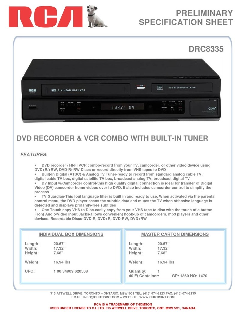
RCA DRC8335 - DVD Recorder & VCR Combo User manual

RCA
RCA DRC8335 - DVD Recorder & VCR Combo User manual

RCA
RCA DRC8005N - Progressive-Scan DVD... User manual

RCA
RCA DRC8040N User manual

RCA
RCA DRC8320N User manual

RCA
RCA GUIDEplus+ DRC8000N User manual

RCA
RCA DRC8060 User manual

RCA
RCA DRC8030N User manual