6. Setting the limit switches
Instructions are for right hand installation {left hand installation in Italics}
a) Set unit in manual mode [see 4 g) above] and move door up by hand to the
desired OPEN position.
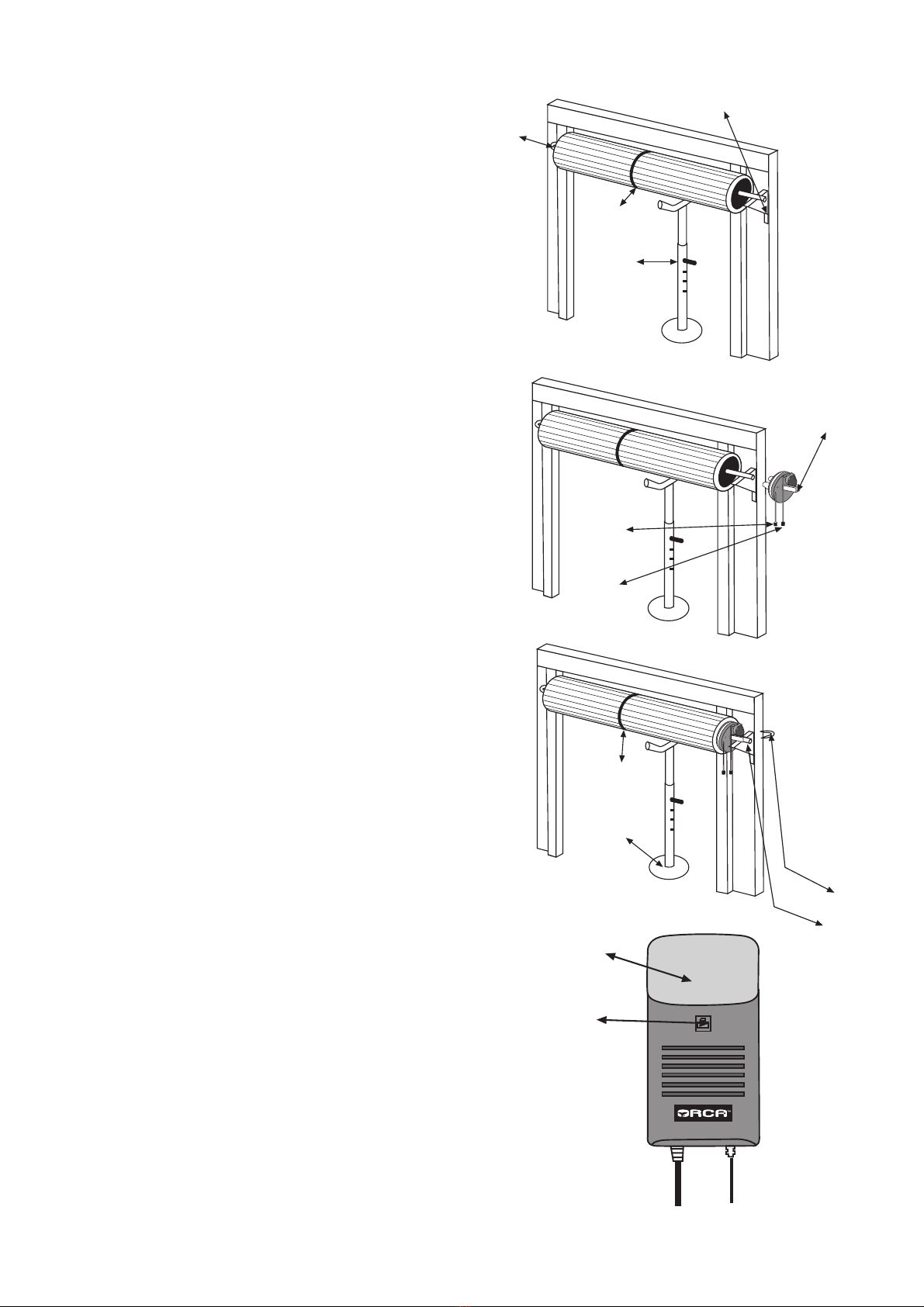
b) Remove the switch cover . Loosen the three black screws holding the cams
in place (Fig 10). The UP LIMIT cam is the inner-most cam. Move this around
clockwise {anti-clockwise} until it fully engages the UP LIMIT switch.
c) Move the door down by hand to the desired CLOSE position. The DOWN
LIMIT cam is the outer-most cam. Move this anti-clockwise {clockwise} until
it filly engages the DOWN LIMIT switch. Tighten the three black screws.
d) Turn the power on and re-engage the drive gear (pull the green cord).
Up Limit Switch Open limit adjustment
e) Press the 0/S/C button on the uncovered board. The door should
start opening. If the door stopped at the desired OPEN position the
limit adjustment is complete. If not, the UP LIMIT cam will have to be
adjusted as detailed above To open the door more, adjust the cam
clockwise {anit-clockwise}
To open the door less, adjust the cam anti-clockwise
Close limit adjustment
f) Press the 0/S/C button on the board again. The door should start
closing. It the door stopped at the desired CLOSE position the limit
adjustment is complete. If not, the DOWN LIMIT cam will have to be
adjusted as detailed above. To close the door more, adjust the cam
anti-clockwise {clockwise} To close the door less, adjust the cam
clockwise {anti-clockwise}
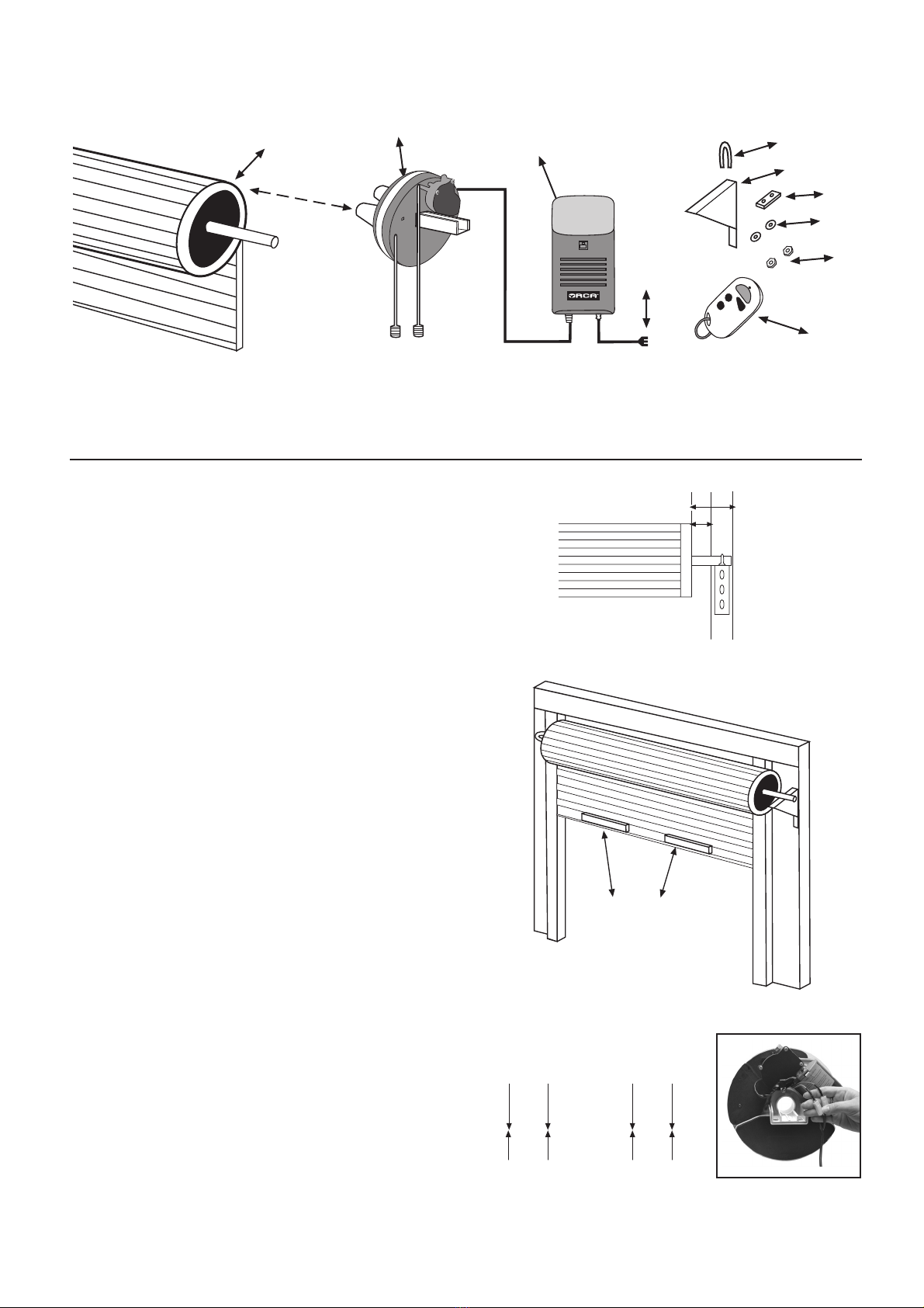
Figure 8
Control Button
Cord
Figure 9
Courtesy Light
Cord
Down Limit Cam
Up Limit Cam
Up Limit Switch
Down Limit Switch
Figure 10
7. Setting force levels for open/close
obstruction detection (Fig 11)
The settings for the open/close obstruction detection force levels are
the most important adjustments in the whole installation procedure.
They are the same for right or left instailation. Failure to set these
levels could result in serious injury or property damage. Once made,
these settings should be tested at regular intervals - once a month
is recommended.
Obstruction detection force level for CLOSE
a) Fully open the door by pressing the 0/S/C button. The door will
stop automatically when the open limit position is reached.
b) Turn the DOWN FORCE knob fully clockwise. Press the 0/S/C
button again - the door should start closing. As the door is closing,
turn the DOWN FORCE knob slowly anti-clockwise until the door
stops momentarily then reverses.
c) Turn the DOWN FORCE knob 10 degrees clockwise. Press the
0/S/C button again to close the door. If the door reverses by itself,
readjust the DOWN FORCE knob a further 5 degrees clockwise. Keep
adjusting in this manner until the door can complete the full closing
cycle.
Obstruction detection force level for OPEN
a) Fully close the door by pressing the 0/S/C button. The door will
stop automatically when the close I limit position is reached.
b) Turn the UP FORCE knob fully clockwise. Press the 0/S/C button
again - the door should start opening. As the door is opening, turn
the UP FORCE knob slowly anti-clockwise until the door stops.
c) Turn the UP FORCE knob 10 degrees clockwise. Press the 0/S/C
button again to open the door. If the door stops by itself, readjust the
UP FORCE knob a further 5 degrees clockwise. Keep adjusting in
this manner until the door can complete the full opening cycle.
Obstruction detection test
The door now has to be tested for response to an obstruction while
it is opening and closing. With the door in the open position, press
the 0/S/C button. The door will start closing. When it reaches about
half way hold the bottom of the door with your hands. If the door
does not readily stop and reverse, the force load setting is too great
and will need adjusting. If the door is unable to reverse, discontinue
use and report the fault to your local distributor. Repeat the test for
the opening cycle.
8. Setting the remote control(s) (Fig 12)
The supplied Remote Control units can be programmed tor any
number of purposes. Although the unit has four buttons, only one is
needed to operate the GarageAce. The same button will open and
close the door. If you have other devices (such as a burglar alarm)
that can program a remote control, use the other buttons for this
purpose.
a) On the CONTROL UNIT board press the LEARN button for 2
seconds. The LEARN LED will turn on.
b) Press the preferred button of REMOTE CONTROL then release
and press again. The LEARN LED will flash about 8 times then turn
off.
c) Press the remote control to test the door open i ng/closing.
d) Repeat these steps for each Remote Control. A maximum of six
remotes can be programmed.
e) It you wish to delete the codes, press and hold the LEARN BUTTON.
The LEARN LED will turn on. Keep holding the LEARN BUTTON for
approx. 8 seconds until the LEARN LED turns off. All stored codes
are deleted. (Recommended if a remote is lost or stolen).
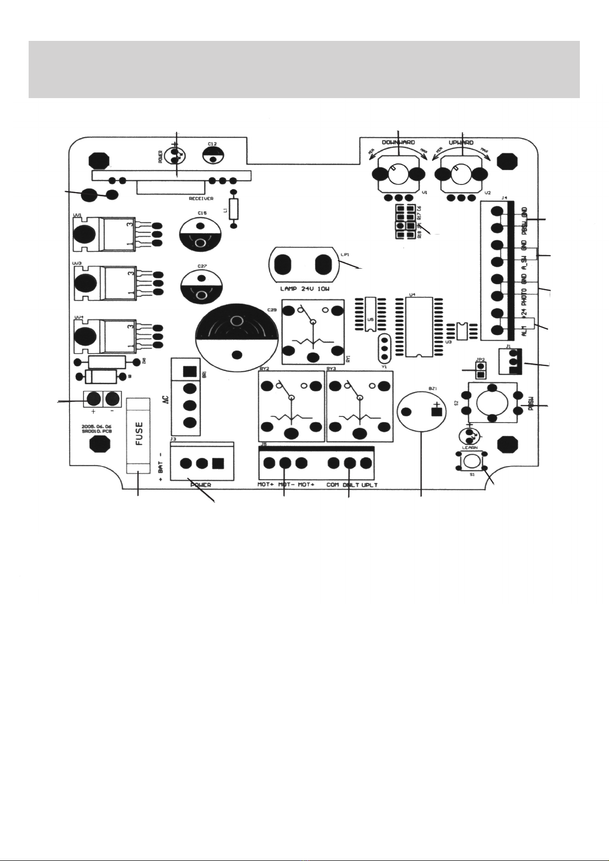
Remote Learn LED
light
Remote
Learn
Button
Figure 12
Downward
Upward
Minimum
Maximum
Figure 11