RCbenchmark 1780 Series User manual

Series 1780 Dynamometer 75 kgf - 500 A
User Manual V2.0 Document ID: DSN10D
Publication date: 2020-04-20
Series 1780 Dynamometer 75 kgf - 500 A
User Manual V2.0
Manual SKU#: ZXMJ
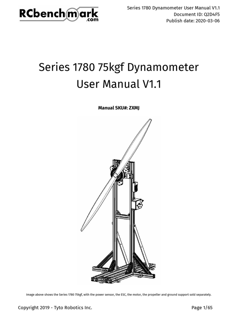
Image above shows the Series 1780 Dynamometer 75 kgf - 500 A: Coaxial.
Copyright 2020 - Tyto Robotics Inc. Page 1/82

Series 1780 Dynamometer 75 kgf - 500 A
User Manual V2.0 Document ID: DSN10D
Publication date: 2020-04-20
Table of contents
Chapter 1: Introduction 5
1.1 Item checklists for the dynamometer 6
1.1.1 Series 1780 Dynamometer 75 kgf - 500 A: Single motor (SKU#: KURKE) 6
1.1.2 Series 1780 Dynamometer 75 kgf - 500 A: Coaxial (SKU#: KXQVH) 6
1.1.3 Accessories 7
Chapter 2: General safety rules 8
Chapter 3: Ground mounting and enclosure 11
3.1 Mounting options 11
3.1.1 With concrete screws 11
3.1.2 Plywood on the floor 12
3.2 Build your own enclosure 14
3.2.1 Design and build your own enclosure 14
Chapter 4: Series 1780 installation 16
4.1 Ground and stand support 17
4.1.1 What’s included and where to find the parts 18
4.1.2 Assembly of the ground structure 19
4.1.3 Assembly of the stand structure 21
4.1.4 Ground and stand structure assembly for single motor 28
4.1.5 Ground and stand structure assembly for coaxial 33
4.2 Load measurement unit 40
4.2.1 Storage, calibration, and warranty 40
4.2.2 What’s included 42
4.2.3 Mounting the load measurement unit to the stand 42
4.2.4 Dismounting the load measurement unit from the support 47
4.3. Motor, motor mount, and optical RPM probe 48
Copyright 2020 - Tyto Robotics Inc. Page 2/82

Series 1780 Dynamometer 75 kgf - 500 A
User Manual V2.0 Document ID: DSN10D
Publication date: 2020-04-20
4.3.1 What’s included 49
4.3.2 Install your motor onto the motor mount 49
4.3.3 Install the optical RPM probe on the motor mount 50
4.3.4 Install the motor mount assembly on the load measurement unit 54
4.4 Power and control console 59
4.4.1 Introduction to the power and control console 100 V - 500 A 59
4.4.2 What’s included and where to locate the components 59
4.4.3 Attaching the power and control console to the stand structure 60
4.4.4 Attaching the ESC on the stand structure 62
4.5 Main board 63
4.5.1 What’s included 64
4.5.2 Installing the main board on the ground or on the stand structure 65
4.6 Tightening with a torque wrench 66
Chapter 5: How to connect electrical components 67
5.1 Electrical safety rules 67
5.2 Sensor chain 68
5.2.1 Optical RPM probe and force sensor 68
5.2.2 Power sensor 69
5.2.3 Temperature probe 70
5.2.4 Air-speed probe 70
5.3 Control chain 70
5.3.1 Power and control console 70
5.4 Main board and PC 71
5.4.1 Indicator lights 71
5.4.2 Power and USB to your PC 72
5.4.3 Buzzer and safety cut-off switch 72
5.5 Cable management 72
Copyright 2020 - Tyto Robotics Inc. Page 3/82

Series 1780 Dynamometer 75 kgf - 500 A
User Manual V2.0 Document ID: DSN10D
Publication date: 2020-04-20
Chapter 6: Coaxial (two-motor) testing 73
6.1 Two motors face-to-face 73
6.2 Two motors back-to-back 75
6.3 Using coaxial to test one motor 76
Chapter 7: Using the RCbenchmark software 77
7.1 Connecting to the tool 78
Chapter 8: Upgrade, warranty, and technical support 79
8.1 Technical support 79
8.2 Upgrade your products 79
8.3 Product’s warranty 80
Annex 1. Support rod angle in coaxial setup 81
Annex 2. Suggested torque specifications 82
Copyright 2020 - Tyto Robotics Inc. Page 4/82

Series 1780 Dynamometer 75 kgf - 500 A
User Manual V2.0 Document ID: DSN10D
Publication date: 2020-04-20
Chapter 1: Introduction
This is the user manual for customers who have purchased the Series 1780 Dynamometer 75
kgf - 500 A. The goal of this user manual is to present all the important information about
preparing, assembling, and using this dynamometer. If you need the user manual for the
Series 1780 Dynamometer 25 kgf V1, the V2 25 kgf - 100 A, or the 40 kgf - 150 A, contact us at
The user manual for the Series 1780 is regularly updated. To ensure you have accurate
up-to-date information, look for the latest PDF copy on our website:
https://rcbenchmark.gitlab.io/docs/en.
IMPORTANT!
We highly recommend that all operators who will be working with this thrust stand read this
user manual carefully in its entirety before carrying out any operation on the Series 1780.
Note that not following the instructions in this user manual may result in testing errors,
malfunction of the dynamometer, serious injuries, or death of the operator.
In this manual, any text following a # represents the RCbenchmark SKU# for this item. You
may refer to this code to order spare parts or to locate malfunctioning parts when you need
technical support.
The Series 1780 dynamometer contains several major units: the load measurement unit(s),
the power and control console(s), the main board, and the ground and stand structure. Every
box may contain one or multiple bags of fasteners. Keep them inside the boxes until you
need to use them.
The load measurement unit, the 75 kgf - 48 Nm A side (#FVET) and B side (#JTJB), is extremely
sensitive to any external forces outside its rated output. The load measurement unit comes
with a protective shell in its own boxes. Do not take it out until you need to mount it onto the
support. When you unmount the load measurement unit from the support, place it back into
the protective casing. For further information about how to store this unit to keep a valid
warranty, refer to section 4.2.1 of this manual.
Copyright 2020 - Tyto Robotics Inc. Page 5/82

Series 1780 Dynamometer 75 kgf - 500 A
User Manual V2.0 Document ID: DSN10D
Publication date: 2020-04-20
1.1 Item checklists for the dynamometer
Before you use these checklists, verify which configuration you purchased from us. If unsure,
contact us.
1.1.1 Series 1780 Dynamometer 75 kgf - 500 A: Single motor (SKU#: KURKE)
Ensure the following items are in the carton:
●Load measurement unit 75 kgf - 48 Nm: side A (SKU#: FVET) x 1
●Mono main board V2 (SKU#: RHGQ) x 1
●Main board power adapter (SKU#: PGAC) x 1
●Power and control console 100 V - 500 A: A side (SKU#: EMDG) x 1
●Accessories and fasteners for assembly box (SKU#: BCJE) x 1
●Heavy load motor mount V2 (SKU#: XSWU) x 1
●General user manual 75kg (SKU#: ZXMJ) x 1
The following items will be in separate boxes:
●Stand structure box (SKU#: TJLD) x 1
●Ground structure box (SKU#: YXHR) x 1
1.1.2 Series 1780 Dynamometer 75 kgf - 500 A: Coaxial (SKU#: KXQVH)
Ensure the following items are in the carton:
●Load measurement unit 75 kgf - 48 Nm: side A (SKU#: FVET) x 1
●Load measurement unit 75 kgf - 48 Nm: side B (SKU#: JTJB) x 1
●Dual main board V2 (SKU#: GPDE) x 1
●Main board power adapter (SKU#: PGAC) x 1
●Power and control console 100 V - 500 A: side A (SKU#: EMDG) x 1
●Power and control console 100 V - 500 A: side B (SKU#: GCQH) x 1
●Accessories and fasteners for assembly box (SKU#: BCJE) x 1
●Extra fastener box for coaxial (SKU#: PNWW) x 1
●Heavy load motor mount V2 (SKU#: XSWU) x 2
●General user manual 75kg (SKU#: ZXMJ) x 1
The following items will be in separate boxes:
●Stand structure box (SKU#: TJLD) x 2
●Ground structure box (SKU#: YXHR) x 1
Copyright 2020 - Tyto Robotics Inc. Page 6/82

Series 1780 Dynamometer 75 kgf - 500 A
User Manual V2.0 Document ID: DSN10D
Publication date: 2020-04-20
1.1.3 Accessories
If you purchased any of these accessories, you can find them in the main carton that came
with your Series 1780 Dynamometer:
●Series 1780 temperature probe (SKU#: JTKB)
●Series 1780 air-speed probe (SKU#: BJPK)
●Series 1780 calibration checker bar (SKU#: QPZG)
The Series 1780 Dynamometer 75 kgf - 500 A is a stand-alone product. It includes the
necessary fasteners, stand, and ground structure. You DO NOT need the ground railing
system for this version of the dynamometer.
Copyright 2020 - Tyto Robotics Inc. Page 7/82

Series 1780 Dynamometer 75 kgf - 500 A
User Manual V2.0 Document ID: DSN10D
Publication date: 2020-04-20
Chapter 2: General safety rules
Always put safety first! It is your responsibility.
It is extremely important to stay alert and know how each item works. Read this part yourself,
and make sure all your colleagues who will be working on the Series 1780 have carefully read
this guide before using the dynamometer.
Refer to upcoming chapters in this manual for assembly instructions.
The following instructions apply to both operating and maintenance personnel and must be
followed during all phases of operations, service, testing, and repair of this instrument.
To ensure safety, follow these instructions:
1. Before construction, make sure all your tools are in good condition and don’t need to
be replaced.
2. Inspect all fasteners before every experiment. Use a thread locker when replacing
bolts.
3. Make sure to use properly rated cables for power.
4. Do not use power tools in the presence of flammable liquids or gases.
5. Always keep your work area clean; do not work on surfaces that are dirty with oil.
Small metal chips may be blown up and hit the propeller by accident. Clean your
testing room before every test.
6. Respect Murphy's law. If you think something might go wrong, it will.
7. Make sure you are dressed for safety. The load cell parts may be sharp, so wear gloves
all along the assembly. Do not wear jewelry or inappropriate clothing when operating
the tool.
8. Do not allow children to be around the Series 1780 dynamometer.
9. Never force the tool to do a job for which it was not designed or is outside its
specifications. Using the tool outside of its official specifications will void the
warranty and is done so at your own risk.
10. Do not use or assemble the tool alone.
11. Do not substitute parts or modify the instrument.
Copyright 2020 - Tyto Robotics Inc. Page 8/82

Series 1780 Dynamometer 75 kgf - 500 A
User Manual V2.0 Document ID: DSN10D
Publication date: 2020-04-20
12. Always disconnect the power source before making adjustments, changing parts, and
cleaning or working on the tool.
13. Do not store anything near or above the tool, especially when it is in use.
14. Always keep your tools clean and in good working order.
15. Do not operate the tool if you are under the influence of drugs, alcohol, or medication
that may affect your ability to properly use the tool.
16. Do not open and touch the electrical circuits inside the enclosures (power and control
console, main board, force sensor circuit). Do not change or modify the electrical
circuit.
17. Respect the manufacturer’s specification concerning the power, voltage, and current
of the motors that you use on the Series 1780 Dynamometer.
18. Make sure you are running all your tests in a safe space. The tool should be fenced off
so unsuspecting personnel cannot enter the test area. Build a safety cage around the
test area. Before a test, assume the propeller will break, and check whether there is a
risk of injury from debris bouncing directly off the propeller or off the walls.
19. The safety cage or the enclosure should be suitably rated for containing a propeller
failure. It should also protect operators in case the Series 1780 comes apart (loose
screw or mechanical failure).
20. Make sure nobody is in the room or near the propeller when the motor tested is
powered.
21. Wait for the propeller to stop spinning and the voltage measured at the ESC to be 0 V
before accessing the testing area.
22. Make sure all the parts have time to cool down after all tests, unless this is part of the
test design. The motor, ESC, batteries, and wires may be hot. Keep a fire extinguisher
available.
23. Make sure a protective surface is between you and the propeller during a test. Wear
protective glasses at all times while in the testing room.
24. For the installation of the components in the Series 1780, always refer to the proper
chapter in this manual. Always use the supplied fasteners and a torque wrench when
specified. Confirm the structure’s rigidity every time before any tests.
Copyright 2020 - Tyto Robotics Inc. Page 9/82

Series 1780 Dynamometer 75 kgf - 500 A
User Manual V2.0 Document ID: DSN10D
Publication date: 2020-04-20
25. Unbalanced propellers and extreme vibrations can lead to fatigue failure of some
aluminum components and/or the load cells. Ensure the unit is completely enclosed
in the safety area, and inspect all parts before performing a test.
26. Note that unbalanced propellers may cause resonances and powerful vibrations
which may result in structure failure and can endanger someone. If you find your
structure vibrating due to resonances, stop the test immediately.
27. If you are using your own fixtures to support the measurement tool, make sure they
are rigid and solid enough to support your loads.
28. Ground railing systems and enclosures must be properly secured to the ground.
29. Do not approach the Series 1780 before cutting off the power to the motor.
30. Use the included lock washers; they are important because of the high vibration from
the propulsion system.
Copyright 2020 - Tyto Robotics Inc. Page 10/82

Series 1780 Dynamometer 75 kgf - 500 A
User Manual V2.0 Document ID: DSN10D
Publication date: 2020-04-20
Chapter 3: Ground mounting and enclosure
IMPORTANT!
You should prepare and assign the test area before assembling the Series 1780
Dynamometer.
3.1 Mounting options
IMPORTANT!
Using no fixture or leaving the Series 1780 improperly secured may cause injury, death,
permanent damage to the load measurement unit, or damage to your facility. Check the
safety guide for more information.
3.1.1 With concrete screws
The preferred mounting method is on a concrete floor with concrete screws. Make sure to use
the given number of L-brackets to fix the ground structure:
●Single motor: 10 L-brackets
●Coaxial: 14 L-brackets minimum, supplied 16
We recommend to use the concrete screws with the following specifications:
●5/16” hex washer head with a minimum length of 2-1/2” or M8 cap or flanged head
with a minimum length of 60 mm
●Made of carbon steel
●Rated for concrete, brick, and hollow block application
●A pull-out rating of at least 100 kgf (220 lbf) each
Fig. 3.1 Example of the concrete screws
Copyright 2020 - Tyto Robotics Inc. Page 11/82

Series 1780 Dynamometer 75 kgf - 500 A
User Manual V2.0 Document ID: DSN10D
Publication date: 2020-04-20
Follow the manufacturer’s installation instructions for the concrete screws.
3.1.2 Plywood on the floor
If your facility does not allow you to drill into the concrete flooring, you may use a large
piece of plywood and place heavy weights at each corner of the plywood along with rubber
pads to increase friction between the plywood and the floor. There is a high bending moment
at the base of the tool, so make sure to use washers and sufficiently thick plywood to handle
it. The screw heads can easily break through the plywood under a heavy load.
It is your responsibility to make the base of your structure suitable for supporting the Series
1780.
To use the plywood, make sure to have enough counterweights on each corner of the
plywood.
Example
Build a 3 x 1.7 m plywood panel (at least 40 mm thickness). The density of plywood is about
680 kg.m³, so your total weight should be close to 160 kg (140 kg of plywood and 20 kg for the
structure). We suggest drilling at least eight holes in the panel and fix it onto levelling
mounts to place it flat on the floor, as shown in Fig. 3.2 and Fig. 3.4:
Fig. 3.2: Levelling mounts on the plywood
IMPORTANT!
For reference only, you may adjust the dimension and position of the counterweights
according to your lab size. Run proper calculations!
Copyright 2020 - Tyto Robotics Inc. Page 12/82

Series 1780 Dynamometer 75 kgf - 500 A
User Manual V2.0 Document ID: DSN10D
Publication date: 2020-04-20
Fig. 3.3: Location of holes for the levelling mounts (dimensions in millimeters)
In addition to a levelling mount, our calculations suggest using four counterweights of 40 kg
each. You could place your weights at the four corners of the tool, as shown in Fig. 3.4. The
farther away these weights are from the stand on the plywood, the more stable the whole
ground fixture will be. Make sure your propellers and airflow will not interfere with these
weights.
Fig. 3.4: Placing the counterweights on the plywood
Copyright 2020 - Tyto Robotics Inc. Page 13/82

Series 1780 Dynamometer 75 kgf - 500 A
User Manual V2.0 Document ID: DSN10D
Publication date: 2020-04-20
To finish the installation of the plywood panel, you will also need to drill holes in the panel
at the location of the L-brackets. You may drill these holes after building the ground metal
structure, as detailed in Chapter 4.1.2. It will be easier to drill these holes after the L-brackets
are installed on the structure.
Fig. 3.5: Attached L-bracket on the plywood
The L-brackets can be used for M8 or 5/16” screws and bolts. If feasible, add lock washers to
avoid screws being loosened due to vibration.
3.2 Build your own enclosure
IMPORTANT!
Having the propeller spinning in an open area and running tests without a proper casing,
duct, cage, or enclosure can be extremely dangerous to the operators and the facility.
You must have strong enough material for the enclosure, especially in the plane of the
spinning propellers. The material should be capable of absorbing the energy from the debris
of propellers.
3.2.1 Design and build your own enclosure
For security reasons, the following points are important:
●Your enclosure is large enough to hold your propellers
●Easy access to any operator for future installation
●Emergency exits are not blocked
●The panel walls can absorb energy from debris
●The room has enough room for the downwash
Copyright 2020 - Tyto Robotics Inc. Page 14/82

Series 1780 Dynamometer 75 kgf - 500 A
User Manual V2.0 Document ID: DSN10D
Publication date: 2020-04-20
Before starting to design the enclosure, know what size propellers you are planning to test.
Generally, you should leave at least 12” (300 mm) between the propeller’s blade tips and all
panel walls made of mesh. Solid panels should be at least one radius away from the tip of
the propeller.
For example, if you are planning to test a 60” propeller, you should design your safety cage at
least 84” wide and 84” high if the wall is mesh. And you should design the enclosure at least
120” wide if the wall is concrete or plywood.
We also recommend having the downwash clearance be five times the maximum propeller
diameter. Downwash can generate severe turbulence and affect the accuracy of thrust and
torque measurements.
Do not place the stand horizontally because the operators would be more likely to be in the
rotation plane of the propeller.
When possible, we always suggest having the thrust stand in its own room and not share the
space with other test equipment. All operators will vacate from the enclosure or the whole
testing room when the power is turned on. The power supply must be located outside the
enclosure.
Copyright 2020 - Tyto Robotics Inc. Page 15/82

Series 1780 Dynamometer 75 kgf - 500 A
User Manual V2.0 Document ID: DSN10D
Publication date: 2020-04-20
Chapter 4: Series 1780 installation
We suggest assigning and preparing the safety area and building the enclosure prior to the
assembly and installation of the 75 kgf - 500 A version of the Series 1780, refer to the previous
section for installing the tool on the ground.
In this chapter, we will present a guide for installing the Series 1780 Dynamometer. Every
section in this chapter represents the suggested procedure for assembling and installing the
Series 1780. Follow the sequence accordingly, and do not bypass any operations.
When you are ready to start with the Series 1780 installation, first, prepare the correct tools
for the operations. You can find inside the package a bag of hand tools (SKU#: AMXZ) in the
fixture and fastener box (SKU#: BCJE), which includes several sizes of Allen keys and
wrenches. If you are using your own tools, make sure to have the proper drive sizes.
Fig. 4.1: Allen key Fig. 4.2: Wrench
Follow these steps to install the Series 1780:
1. Ground and stand support
2. Load measurement unit
3. Motor, motor mount, and optical RPM probe
4. Power and control console
5. Main board
Copyright 2020 - Tyto Robotics Inc. Page 16/82

Series 1780 Dynamometer 75 kgf - 500 A
User Manual V2.0 Document ID: DSN10D
Publication date: 2020-04-20
4.1 Ground and stand support
The support is the largest mechanical structure of the Series 1780. It is designed to be placed
on the ground and to support and sustain all loads generated by the motors and propellers.
You may also use it to fix the ESC and the power and control console on it.
Fig. 4.3: 75 kgf coaxial version ground and stand support
Copyright 2020 - Tyto Robotics Inc. Page 17/82

Series 1780 Dynamometer 75 kgf - 500 A
User Manual V2.0 Document ID: DSN10D
Publication date: 2020-04-20
IMPORTANT!
This structure was carefully designed, calculated, and tested to hold loads and vibrations
from one or two propellers producing the maximum rated thrust. You must follow the
instructions to properly assemble the structure and firmly tighten all the supplied fasteners.
Missing parts or loose fasteners are very dangerous during a test.
4.1.1 What’s included and where to find the parts
When you have the Series 1780 Dynamometer 75 kgf - 500 A: Single motor, you will use the
following list of boxes to start the assembly:
Item name
Item SKU
Qty
Ground structure box
YXHR
1
Stand structure box
TJLD
1
Fixture and fastener box
BCJE
1
When you have the Series 1780 Dynamometer 75 kgf - 500 A: Coaxial, you will use the
following list of boxes to start the assembly:
Item name
Item SKU
Qty
Ground structure box
YXHR
1
Stand structure box
TJLD
2
Fixture and fastener box
BCJE
1
Extra fastener box for coaxial
PNWW
1
Retrieve the hand tools immediately from the fixture and fastener box (#BCJE):
Hand tools bag (SKU#: AMXZ)
Item name
Item SKU
Qty
Allen key 3/16”
TRHE
1
Allen key 1/4”
QYHR
1
Allen key 4 mm
5WUH
1
Wrench 8 mm x 10 mm
9AGF
1
Copyright 2020 - Tyto Robotics Inc. Page 18/82

Series 1780 Dynamometer 75 kgf - 500 A
User Manual V2.0 Document ID: DSN10D
Publication date: 2020-04-20
To avoid mistakes using the wrong screws in the Series 1780 assembly, keep the fasteners in
the bags until you need them. Keep all the empty fastener bags in case you need to
disassemble the structure so you can place the fasteners back in the appropriate bag.
4.1.2 Assembly of the ground structure
Note that both versions of the 75 kgf - 500 A thrust stand use the same ground base. Retrieve
the following items from the boxes:
Item name
Item SKU
Qty
Located in (SKU# if exist)
T-slotted double frame 4’ long
VYTV
2
75 kgf ground structure box (#YXHR)
T-slotted double frame 4” long
WHXZ
2
Fixture and fastener box (#BCJE)
L bracket
KPHT
2
Fixture and fastener box (#BCJE)
Gusset bracket
YKPV
4
Fixture and fastener box (#BCJE)
Beam fastener bag
WVKM
1
Fixture and fastener box (#BCJE)
You will need these items from the beam fastener bag (#WVKM):
Item name
Item
SKU
Qty
Button head 5/16”-18 screw 11/16”
long
KEDB
10
End-feed T-nut 5/16”-18
YREC
10
To start:
❏Take two T-slotted double beams 4” (#WHXZ) out of the fixture and fastener box
(#BCJE).
❏Take two T-slotted double beams 4’ (#VYTV) out of the ground structure box (#YXHR).
❏Place these four T-slotted frames (#WHXZ and #VYTV) on a worktable.
❏Take ten button head 5/16”-18 screws (#KEDB) and ten end-feed T-nuts (#YREC) out of
the beam fastener bag (#WVKM).
Copyright 2020 - Tyto Robotics Inc. Page 19/82

Series 1780 Dynamometer 75 kgf - 500 A
User Manual V2.0 Document ID: DSN10D
Publication date: 2020-04-20
Fig. 4.4: L-bracket Fig. 4.5: Gusset bracket
❏Take four gusset brackets (#YKPV) and two L-brackets (#KPHT).
❏Fix on one short side of the T-slotted double beam 4” (#WHXZ) two gusset brackets
(#YKPV) with button head 5/16”-18 screws (#KEDB) and T-nut fasteners (#YREC), shown
in Fig. 4.6.
❏On another single side, fix an L-bracket (#KPHT) at the middle of the T-slotted double
beam 4” (#WHXZ) with the button head 5/16”-18 screws (#KEDB) and T-nut fasteners
(#YREC), as shown in Fig. 4.6.
Fig. 4.6: Two gussets (#YKPV) and one L-bracket (#KPHT) attached to the T-slotted double frame 4” (#WHXZ)
❏Make the second assembly, as shown in Fig. 4.6, with the supplied components.
❏Attach the assemblies from the last step at each end of the two T-slotted double
beams 4’ (#VYTV), connect and close the structure with button head 5/16”-18 screws
(#KEDB) and T-nuts (#YREC), as shown in Fig. 4.7.
Copyright 2020 - Tyto Robotics Inc. Page 20/82
Other manuals for 1780 Series
2
This manual suits for next models
2
Other RCbenchmark Measuring Instrument manuals
Popular Measuring Instrument manuals by other brands

MRC
MRC PMG-302 Operation manual

Keysight Technologies
Keysight Technologies N9020A Installation note

Fuji Electric
Fuji Electric ZaFe instruction manual

Teledyne
Teledyne HFM-301 instruction manual

Siemens
Siemens SITRANS FC430 Compact operating instructions

Lutron Electronics
Lutron Electronics EMF-819 Operation manuals