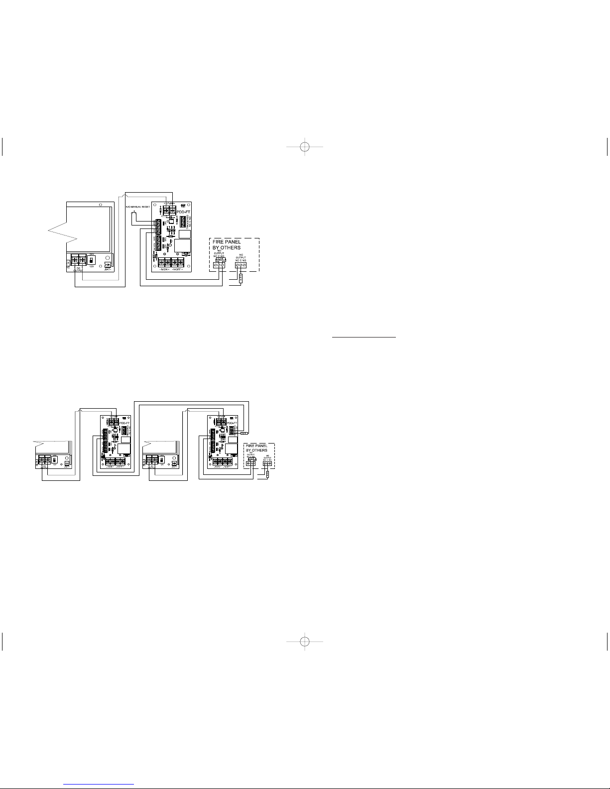
FIG. 5 - Connections for latching release with N/O manual reset using
multiple PDD-FT boards
This application illustrates how to connect the PDD-FT to a power supply for main input
as well as a fire alarm control panel. If wired in this manner, outputs will change state
whenever the fire alarm relay activates and remain latched in the triggered state until reset
by activating the N/O switch. Connecting the EOL input of one board to the trigger relay of
the next boardas shown will allow for override and reset of multiple boards.
Note: The RST jumper must be left in place on all boards except the one that is
directly connected to the fire alarm,reset, and override switches.
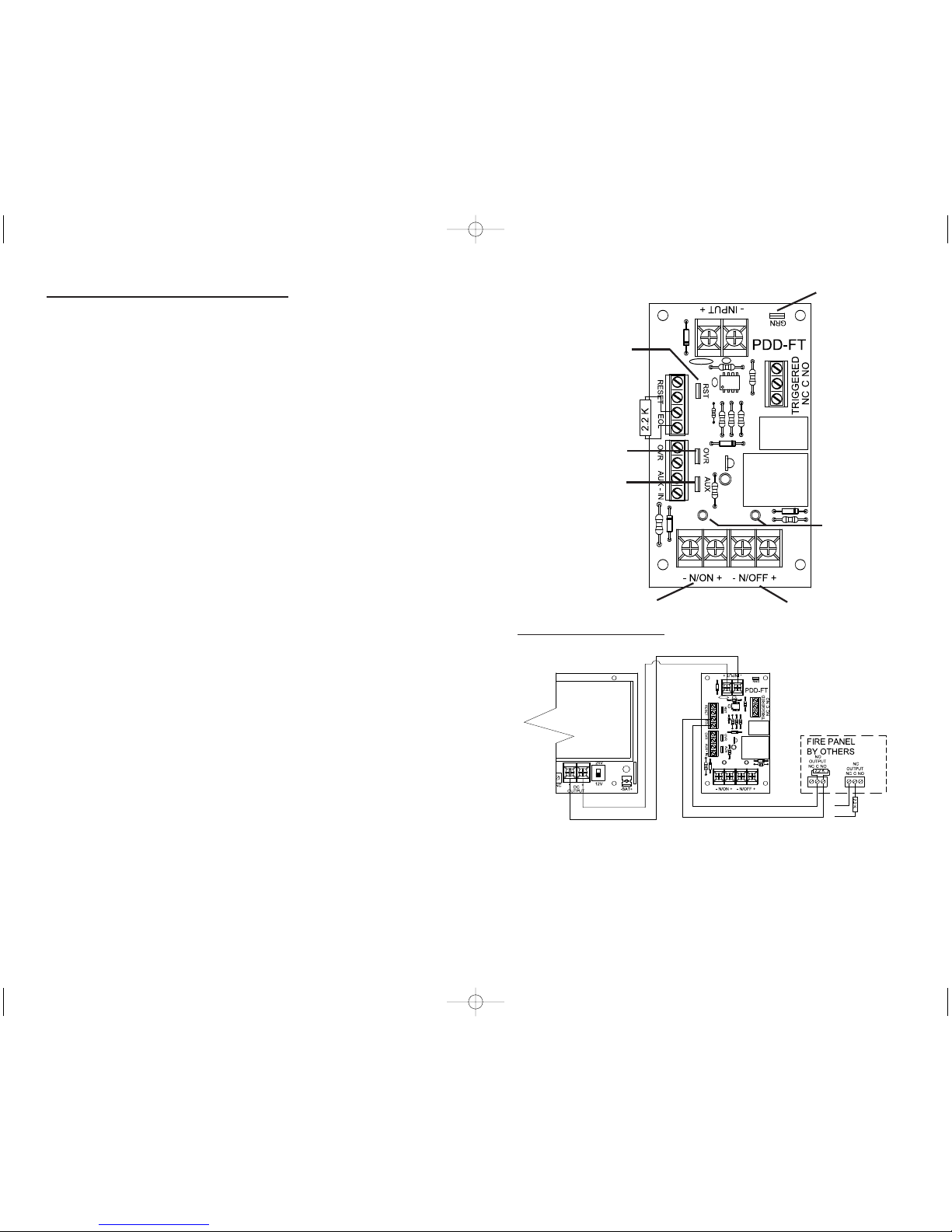
FIG. 6 - Fire Panel
Connections for
Latching Trigger
with N/O Manual
Reset w Battery
Backup
This application
illustrates how to
connect the PDD-FT to
an RCI 10-5 for main
input, AC failure as well
as a firealarmcontrol
panel. If wired in this
manner, trigger outputs
will change state
whenever the fire alarm, or AC failure relays activate. The PDD-FT outputs will remain in
the triggered state until both relays have been reset and the N/O manual reset is triggered.
Note: Ensure jumpers for RST, OVR, and AUX IN are removed
to allow terminals to operate correctly.
Details
The PDD-FT board is a fire panel control interface. This board can be used to control DC
output based on a fire alarm control panel. Two outputs switch state on alarm.
Features
3Non Latching or Latching mode
3Universal 12VDC or 24VDC Operation
3Reverse polarity protected
3Normally ON & Normally OFF Output
3Output LED’s indicate condition
3Outputs can be Triggered with:
1) N/O or N/C Switch with Supervised (EOL)
2) N/C Switch with (OVR) over ride
3) N/C Switch with AUX-IN auxiliary
4) Ground on any trigger input when (GRN) Jumper is enabled
3Form C Contacts Indicates Trigger Status
312 Amp Transfer Relay Contacts
Installation Instructions
1. Mount the PDD-FT board in a suitable location in close proximity to the power supply.
Note:
a) Ground fault detection will only work if conductive stand offs areused and
power supply enclosureis properly grounded.
b) As this device is used to power multiple devices ensure that all wiring is of an
appropriate gauge for the devices being installed.
c) The RCI PDD-FT board is for use in a controlled environment. Installation
must be in accordance with local building and fire codes. Check with
Authority Having Jurisdiction (AHJ) for details prior to installing.
d) All power limited wiring must be a minimum of .25” from non-power limited
wiring.
2. Connect “INPUT” terminals to output of DC supply, paying close attention to polarity of
DC output from power supply.
3. Connect devices to be powered to output terminals of PDD-FT
control board, paying close attention to polarity requirements.
4. Set jumpers (RST, OVR, AUX, and GRN) as required for proper installation.
IS10PSFPD_R0711.qxd 7/21/11 6:57 PM Page 2