www.rebellelighting.com
© 2010 REBELLE All rights reserved.
REBELLE ARCHITECTURAL LIGHTING 11475 - 201A Street, Maple Ridge, B.C. Canada V2X 0Y3
1
2
3
4
5
6
7
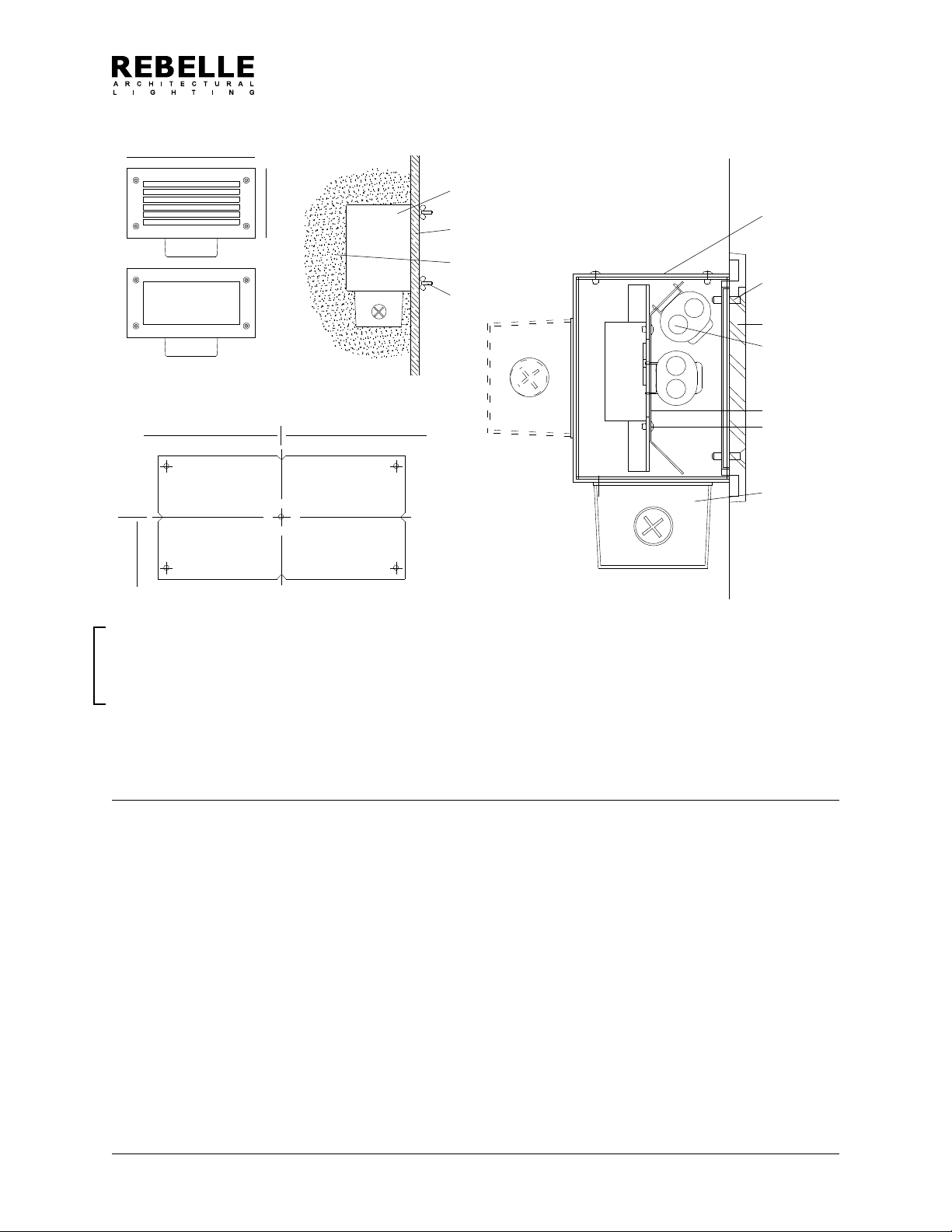
HOUSING INSTALLATION - CONCRETE POUR
Sightlines 1645 Series
Remove housing from shipping carton. Lay out center
line of luminaire positions on concrete form. (Fig.1)
Position template (provided) over marked center line
luminaire spacings (make sure template is level) drill
1/4” holes through form. (Fig.1)
Install housing on concrete side of form using 3” long
studs and wing nuts (provided). Ensure that j-box is
properly oriented down or on back (g.2) Check that
unit is level.
If tile or other surface treatment is used the housing
position must be adjusted to suit prior to pouring con-
crete.
Install 1/2” NPT conduit as required and pull supply
circuit wires per applicable electrical codes.
Conduits must be sealed or plugged at all entry points
as per applicable electrical code.
Remove wing nuts and studs after concrete is cured
before the forms are stripped.
Remove electrical tray from shipping carton.
Remove internal j-box cover from housing and pull out supply
wires. Thread electrical white, black and ground leads through
j-box cover and connect to appropriate supply leads.
Push all splices into j-box and re-attach cover plate.
Install electrical tray with screws provided and insert lamp as
required.
Remove faceplate assembly from shipping carton.
Before continuing mounting surface must be smooth and at to
allow gasket to make good contact for a water tight seal.
Coat screws with white grease and install faceplate to housing
anchor nuts.
Energize and test as required.
IMPORTANT
Disconnect power before installing xtures. Read instructions before
starting work. This product must be installed in accordance with the
applicable installation code by a person familiar with the construction
and operation of the product and the hazards involved.
1
2
3
4
5
6
7
8
ELECTRICAL TRAY AND FACEPLATE INSTALLATION
11"
6" Housing
Concrete form
(by others)
Housing
Faceplate
mounting
screws
Faceplate
Concrete
(by others)
Studs and wing
nuts
Spacing to
center line
Spacing to
center line
Figure 1
Height to
center line
Figure 2
Electrical tray
Electrical tray
J-Box (optional
rear mount)
Lamps
(by others)
REV. 06/28/10


