Reclaim REHP-CO2-160GL-V2 Owner's manual

QUICK START/INSTALL MANUAL
AIR-SOURCE CO2 HEAT PUMP HOT WATER SYSTEM
INSTALLATION
OPERATION
MAINTENANCE
For the full version of installation
and owner manuals, please visit:
reclaimenergy.com.au/downloads
PRODUCT
UPDATE
V2 RELEASE

Reclaim Energy |Quick Start/Install Manual – v2.0
2
COVERING MODEL NUMBERS
(FOR STC CLAIMS):
REHP-CO2-160GL-V2
REHP-CO2-250GL-V2
REHP-CO2-315GL-V2
REHP-CO2-400GL-V2
REHP-CO2-160SST-V2
REHP-CO2-250SST-V2
REHP-CO2-315SST-V2
REHP-CO2-315SSQ-V2
REHP-CO2-400SST-V2
REHP-CO2-250SS-WIL-V2
REHP-CO2-315SS-WIL-V2
REHP-CO2-250SSEW-V2
REHP-CO2-315SSEW-V2
DIGITAL COPY OF OUR
MANUALS?
For a full set of PDF manuals and brochures, visit:
reclaimenergy.com.au/downloads OR
simply scan the QR Code below:
Issue 02 | Jan 2023
IMPORTANT
This appliance is not intended for use by persons (including children) with reduced physical, sensory or
mental capabilities, or lack of experience and knowledge, unless they have been given supervision or
instruction concerning use of the appliance by a person responsible for their safety. Children should be
supervised to ensure that they do not play with the appliance.
WARNING
This appliance may deliver water at high temperature. Refer to the Plumbing Code of Australia (PCA), local
requirements and installation instructions to determine if additional delivery temperature control is required.

Quick Start/Install Manual – v2.0 | Reclaim Energy
RECLAIMENERGY.COM.AU 3
SECTION PAGE
Product Update Overview 4
First Time Commissioning Procedure 8
1System Description 10
2Installation Details 11
2Checklist 21
3Operation & Maintenance 22

Reclaim Energy |Quick Start/Install Manual – v2.0
4
FEB 2023 PRODUCT SUPPLY CHANGES
As of February 2023, Reclaim Energy will launch the next generation of heat pump with
some substantial improvements. Unless specified below, all other parameters/
specifications are the same between V1 and V2 models. The two key changes are
summarised in Table A and Table B below:
V1 V2
STATUS DISCONTINUED FROM 2023 AVAILABLE FROM 2023
Model Name EHPE-4540P EHPE-4550P-A
Max rated power input (kW) 2.3 2.5
COMPRESSOR
Compressing volume (cm3)3.80 4.5
Refrigeration Capacity (W) 3470 4900
Communications with the controller RJ45 cable Modbus
Connectivity to controllers V1 & V1.1 models ONLY V1, V1.1, V2 models
Table A: Key updates on the Reclaim Energy heat pump
PRODUCT
UPDATE
V2 RELEASE
COMES WITH:
• Power cable
• Temperature sensor cable
• RJ45 cable
COMES WITH:
• Power cable
• Temperature sensor cable
• RJ45 cable
COMES WITH:
• Power cable
• Temperature sensor cable
• Modbus cable
V1 DISCONTINUED V1.1 V2
Figure A: The images of 3 controllers

Quick Start/Install Manual – v2.0 | Reclaim Energy
RECLAIMENERGY.COM.AU 5
V1 V1.1 V2
STATUS DISCONTINUED
FROM 2023
AVAILABLE FROM
FEBRUARY 2023
SOFT LAUNCH FROM
FEBRUARY/MARCH 2023
Connectivity
to heat pump RJ 45 cable RJ 45 cable Modbus
Connectivity to PV
inverters and home
management systems
Not available Dry Contact
Connectivity to
Reclaim Mobile app
using house Wifi
Not available Available
Option 1 24/7 time-block
Option 2 10 pm – 7 am
Option 3 Midnight – 6 am
Option 4 10 am – 4 pm
Option 5 Two time-blocks – first
must set for a minimum
of 6 hours and second
can be set as little as 0
hours!
Two time-blocks – first must
set for a minimum of 3 hours
and second can be set as
little as 0 hours!
Two time-blocks – first must set for
a minimum of 3 hours and second
can be set as little as 0 hours!
Additionally, the turn on temperature
can be adjusted for the second time
block (i.e., default is 37°C)
Option 6 N/A
One shot boost is activated by
a dry contact signal from
home management or PV
inverters or dry contact
smart switches
This is called “Remote”
option
Two time-blocks – first must set for
a minimum of 3 hours and second
can be set as little as 0 hours!
Additionally, both turn on temperature
and turn off temperatures can be
adjusted for the second time block
(i.e., default is 37°C & 59°C,
respectively.)
Option 7 N/A
One shot boost is activated by a dry
contact/modbus signal from home
management or PV inverters or dry
contact smart switches
This is called “Remote” option
Additionally, a time clock should be
adjusted for when the signal is not
received by the controller in the
18-hour cycle (i.e. this is to ensure
the legionella bacterial growth is
controlled in a 24 hour cycle)
Boost function Available
Manuals Website
Table B: Key updates on the Reclaim Energy controllers

Reclaim Energy |Quick Start/Install Manual – v2.0
6
Figure B: Reclaim Energy Mobile App used with V2 controller
PRODUCT
UPDATE
V2 RELEASE
RECLAIM ENERGY
FREE APP
Available for iOS & Android
mobile phones
Connection to Wifi and the mobile app
is OPTIONAL for the end user.
Full functionality of controller can
be used manually or via the FREE
Reclaim Energy app.

Quick Start/Install Manual – v2.0 | Reclaim Energy
RECLAIMENERGY.COM.AU 7
KEY CHANGES ON
THE SYSTEM MODEL
NUMBERS
It is notable that the V2 system model numbers are different to
the previously supplied system model numbers. The following
codes must be used for rebate applications such as STC, ESC,
and VEECs. In terms of STC changes between V1 and V2 models,
there has been slight improvement of about 1-3 STCs for different
model IDs depending the system model number and zone.
The latest up to date values should be checked here:
• STC values:
rec-registry.gov.au/rec-registry/app/calculators/swh-stc-calculator
• VEEC values:
veu-registry.vic.gov.au/Public/Calculator/VEECCalculator.aspx
• ESC values (estimates only):
reclaimenergy.com.au
V2 models – AVAILABLE FROM 2023 V1 models
Item Tank Model ID Heat Pump Model ID System Model Number Heat Pump Model ID System Model Number
1 RE160AGLH
EHPE-4550P-A
REHP-CO2-160GL-V2
EHPE-4540P
REHP-CO2-160GL
2 APS160TH REHP-CO2-160SST-V2 REHP-CO2-160SST
3 RE160WIL REHP-CO2-160SS-WIL-V2 REHP-CO2-160SS-WIL
4 RE250AGLH REHP-CO2-250GL-V2 REHP-CO2-250GL
5 EWA-250HPT REHP-CO2-250SSEW-V2 REHP-CO2-250SSEW
6 APS250TH REHP-CO2-250SST-V2 REHP-CO2-250SST
7 RE250WIL REHP-CO2-250SS-WIL-V2 REHP-CO2-250SS-WIL
8 TS300-O-E24-S2 REHP-CO2-300H-V2 REHP-CO2-300H
9 RE315AGLH REHP-CO2-315GL-V2 REHP-CO2-315GL
10 EWA-315HPT REHP-CO2-315SSEW-V2 REHP-CO2-315SSEW
11 APS315SH REHP-CO2-315SSQ-V2 REHP-CO2-315SSQ
12 APS315TH REHP-CO2-315SST-V2 REHP-CO2-315SST
13 RE315WIL REHP-CO2-315SS-WIL-V2 REHP-CO2-315SS-WIL
14 RE400AGLH REHP-CO2-400GL-V2 REHP-CO2-400GL
15 APS400TH REHP-CO2-400SST-V2 REHP-CO2-400SST
Table C: Updates on the system model IDs

FIRST TIME COMMISSIONING PROCEDURE
DO NOT plug in the heat pump
or connect the controller
communication cable yet
IMPORTANT NOTE
STEP 1
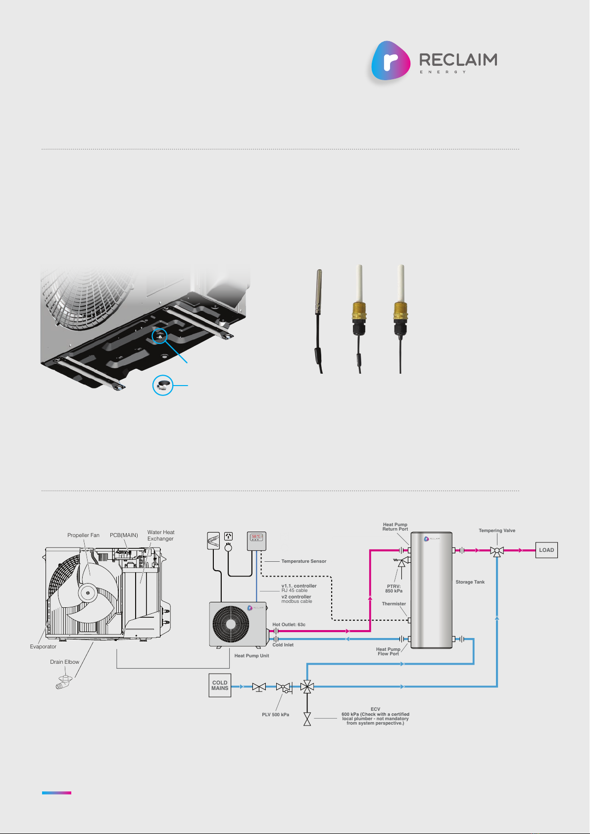
• Ensure the system plumbing comply
with the diagram provided here.
STEP 2
• Ensure the system wiring comply
with the diagram here. Make spacial
attention to sensor insertion on the
lower level of the tank and the
sensor must be fully in.
STEP 3
• Ensure you have filled the tank and
purged all the air by opening a tap
inside the house. The tank will be
purged when water runs freely
from the tap.
• Turn tap off.
• The cylinder has now been purged.
STEP 4
• Purge the circulating pump by
losening the brass 8mm nut on
the underside of the heat pump
untill water runs freely then
tighten again.
• The circulating pump has
now been purged.
STEP 5
Commission the controller
• select correct time of day
• select the desirable operational
mode (i.e. options 1-6)
• power up the controller and
connect the communication
cable to heat pump
STEP 6
• Initiate auto purge and system
start up.
• Ensure the system controller
is turned on and the time is
displayed.
• Ensure the heat pump isolator
is in the on position and power
is on to heat pump unit.
• On the controller, push and hold
the “menu” or “OK” button (i.e.
“menu” for V1 controller and “OK”
for V2 controller) until the word
“purge” is displayed and flashing
(approx 5 seconds).
• Now let go of the button.
• In about 4 seconds you should
hear the on-board circulating
pump come on.
SYSTEM STARTUP SEQUENCE
The system is now starting up and
will go through the following
sequence:
1The system will run a 5 minute
purge that pushes any air within
the heat pump unit into the tank.
Note the unit fan won’t be turning
at this point).
2After this 5 minute period the
pump will stop and the fan will
turn slowly. The system will not
be heating up until the until can
maintain a consistent 63°C (this
may take up to 4 minutes).
3The unit fan comes on properly
and the circulating pump starts to
circulate that constant 63°C water
through the tank.
Due to the smart top down heat
return system your customer
will have 50L of hot water within
20 minutes and a full tank in
about 3 hours.
After 15 minutes touch the heat
pump return connection to the
tank and ensure it is hot to touch,
if you feel good heat here you are
done and can comfortably leave
knowing you have completed
the install successfully.
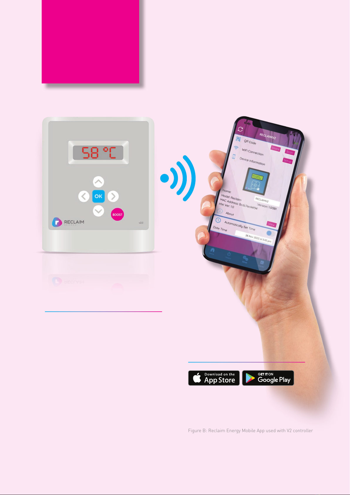
HOW TO USE V1.1 OR V2
CONTROLLERS WITH
THE V2 HEAT PUMP
The V2 heat pump default mode is
with V1.1 controller. As such, if V1.1.
controller is received, simply the
controller can be connected to RJ 45
port on the PCB display of heat pump
and the general commissioning
process to be followed.
If V2 controller is received, the
following steps on the heat pump
is required before V2 controller
can be used:
STEP 1
Connection of correct cable to the
right terminal
• V1.1 controller: RJ 45 terminal
block to be used
• V2 controller: Modbus terminal
block to be used
STEP 2
Change the mode on the PCB display
from 1 to 2 using PCB display
Change the value of “r1” to “2” as
follows:
1. Press and hold UP(▲) and
DOWN(▼) buttons.
2. The value displayed is “r1” & “1”
3. Change the value of “r1” to “2”
by pressing the RIGHT( ) or
LEFT( ) button.
4. Press and hold UP(▲) and
DOWN(▼) button to complete the
setting when display returns to its
original display (i.e. blank display).
5. To check if “r1” & “2” is
established, try step 1 one
additional time and then go to step
4 to exit.
Reclaim Energy |Quick Start/Install Manual – v2.0
8

RECLAIMENERGY.COM.AU
Propeller Fan
Evaporator
PCB(MAIN) Water Heat
Exchanger
Drain Elbow
COLD
MAINS
LOAD
Heat Pump Unit
Hot Outlet: 63c
Cold Inlet
PLV 500 kPa
Storage Tank
ECV
local plumber - not mandatory
from system perspective.)
Tempering Valve
Heat Pump
Return Port
PTRV:
850 kPa
Heat Pump
Flow Port
v1.1. controller
RJ 45 cable
v2 controller
modbus cable
Temperature Sensor
Thermister
ON
OFF
HEATPUMP CONTROL V2.0
EXIT
BOOST
ENTER
PWR
TEMP
HPON
BOOST
FAULT
ERROR
MENUTEMP
58 °C
CRITICAL NOTES
NOTE 1
Remember to drain and purge the heat pump on
commissioning (otherwise system might fail) –
the “drain plug” is shown below. Also, remember
to drain from hot water taps inside the house.
NOTE 3
Maximum horizontal distance is 10 m and
vertical distance is 5 m between heat pump
and tank (max of 3 bendings)
NOTE 2
Sensor probe must be fully inserted and secured
(using gland or silicon plug) in the bottom tank
sensor. The sensor cable comes with a rubber
sleeve.Fully push the sensor in and then push the
cable sleeve until only 6 mm is protruding. Then
tighten up the gland so the sensor is firmly held.
Drain Elbow
Drain Plug
Quick Start/Install Manual – v2.0 | Reclaim Energy 9

Reclaim Energy |Quick Start/Install Manual – v2.0
10
SECTION
The following system description section provides a brief overview of the the Air-Source
CO2 Hot Water Pump’s main components and functionality.
1.1 MAIN COMPONENTS
The system components of the air sourced heat pump that
customers will receive include:
Heat pump Unit, Storage Tank with PTRV, Controller, Heat
pump mounting legs.
1.2 SYSTEM OPERATION
The CO2 heat pump unit receives cold water from the
bottom of the tank. Using the heat from the ambient air
the heat pump heats the CO2 refrigerant to generate hot
water. The hot water returning from the heat pump unit
(fixed at 63°C) is injected into the top of the tank to provide
fast hot water recovery and excellent hot water stratification.
As this system delivers hot water exceeding 50 °C, a
tempering valve must be installed for delivery of hot water
to bathrooms. Untempered water may be delivered to
kitchen and laundry according to AU/NZS AS 3500
plumbing code.
The heat pump operation is controlled by an external
controller. The controller operates based on a sensor
connected to the tank at 55 – 69% level depending on tank
model i.d. The heat pump will be turned on if the
temperature at the sensor level on the tank drops below
59°C for the first cycle or 37°C for the second cycle in a
day and it will be run until the tank temperature at sensor
level reaches 59°C. The system controls are designed to
ensure that it meets the legionella requirements as
specified in the Australian standards. The heat pump will
run until the sensor level on the tank reaches 59°C. In the
subsequent heating cycles of every 24-hour period, the
heat pump “turn off” logic is adjustable by built-in timer
settings.
The default timer setting is programmed to run on
continuous operation but this can be adjusted by the
installer based on the home owner requirements to suit
their needs. More details regarding the controller
operation and settings is outlined in Section 2.
At ambient temperatures below 5.5°C, frosting may occur,
if this happens the heat pump will go into defrost mode in
order to protect the unit (i.e. this defrost functionality will
turn the heat pump on and will normally run for no more
than 15 minutes in duration). When the unit is in the
defrost function the pump and fan will stop and the
refrigerant heat will defrost the evaporator. As defrost
advances, the evaporator temperature will increase.
When a set temperature (preprogrammed) is achieved,
the defrost operation stops and the heat pump will operate
in line with its normal settings. More details regarding the
controller operation and settings is outlined in Section 6.
The “operational window” in this context refers to heat
pump “hot water production” mode which can be set by
using one of the options on the controller. From time to
time, especially during the winter and in very cold
climates, the heat pump operation may be disrupted or
extended by a built-in anti-freeze or defrost operational
mode. The defrost cycle can occur ONLY during the
operational window to defrost the ice build-up on the
evaporator at the back of the unit which is an air-CO2 heat
exchanger. The defrost cycle occurs when the ambient
temperature is less than about 5 °C. During the defrost
operation, the fan and pump stop, and the high-
temperature refrigerant which is originally used for hot
water production shall be supplied in order to melt frosts
on the evaporator (=air-CO2 heat exchanger).
The frost cycle can take about 5 minutes and this can
happen multiple times depending on the ambient
temperature, so in total, up to 20 minutes can be expected
for the entire defrost cycle. The heat pump also comes
with a built-in freeze protection cycle. Anti-freeze
operation can ONLY occur outside the operational window
of the heat pump and the purpose of the cycle is to protect
the water circuit (i.e. piping between tank and heat pump)
from water freezing. If the ambient and water pipe
temperatures drop below 3 °C, the heat pump will do the
anti-freeze operation. During the anti-freeze operation, the
heat pump works as a normal heating cycle so the fan and
pump should be running. The anti-freeze operation stops
when the water inlet temperature reaches 56 °C or
ambient temperature reaches 6 °C.
SYSTEM DESCRIPTION
41

Quick Start/Install Manual – v2.0 | Reclaim Energy
RECLAIMENERGY.COM.AU 11
SECTION
INSTALLATION DETAILS
6
This section relates to the preparation and the installation proccess for the Reclaim
Air-Source CO2 Heat Pump system.
The installation of a Reclaim Energy air source heat pump
can only be completed by a licensed plumber or electrician
in accordance with the local standards and regulations
please see:
• AS/NZS 3000 – Electrical installations rules: Electrical
requirements of the system are 240v, 50 Hz, single
phase, with 20 Amp circuit breaker. This appliance
is to be wired with a disconnection device, as per
AS/NZS 3000 wiring rules
• AS/NZS 3500 – National plumbing and Drainage Code:
The Heat Pump component of the system is to be fitted
outside.
• AS/NZS 2712.2007 – Solar and Heat Pump Water
Heaters: Design and Construction
• AS/NZS AS 3498—2009 – Water heaters and hot-water
storage tanks
A licensed installer must adhere to occupational health
and safety guidelines and other relevant industry
associations. Under no circumstances should any installer
attempt to install a Reclaim Energy system without
reading and understanding this installation manual. For
any queries Reclaim Energy staff may be contacted on
1300 38 38 15.
Note that the Reclaim Energy system has been designed
to provide hot water for domestic applications only, other
applications such as space heating are not supported by
this product. Installing the unit for any other application
other than for domestic hot water application will void the
warranty. The installation guide for each major component
of the system as well as the whole system is covered in
this section.
The following sequence is recommended for installation:
1. Conduct site inspection
2. Identify heat pump and tank installation location
3. Plan system integration: Piping and fittings
4. Testing and commissioning
2.1 SITE INSPECTION AND
INSTALLATION PREPARATION
The very first step of installation is to find an appropriate
location for the installation of the heat pump unit that
includes: heat pump, tank, timer, and the controller.
It is recommended that:
• To reduce the heat loss from piping, the whole system
should be installed as close as possible to the main hot
water points in the house (kitchen and/or bathrooms).
• The maximum distance between controller/timer, tank,
and heat pump should not exceed 10 m. .
• It is recommended that the heat pump is installed on
the ground next to the tank.
• The heat pump unit MUST be installed outdoors,
the tank can be installed indoors.
• The back of heat pump unit draws in ambient ait
therefore it MUST NOT be covered. In order to have
sufficient air circulation behind the heat pump, the
minimum free space should be 0.15 m.
• The system requires at least two GPO power outlets
(one for controller, one for heat pump).
• The mounting surface of tank and heat pump MUST
be horizontal.
• The clearance on front and back of the unit are 350 mm
and 600 mm- please refer to Figure 2.
• The tank MUST be installed on a concrete slab on the
ground.
• Water supply quality must be in line with the
specifications of the heat pump unit and the storage
tank being installed.
2

Reclaim Energy |Quick Start/Install Manual – v2.0
12
SECTION
6
Total Dissolved Solids < 600 mg/L or ppm
Total Hardness (CaCO3) < 200 mg/L or ppm
Electrical Conductivity 850 μS/cm
Chloride < 200 mg/L or ppm
pH Level Min 6.5 to Max. 8
Magnesium < 10 mg/L or ppm
Sodium < 150 mg/L or ppm
Iron < 1mg/L or ppm
Alkalinity (as CaCO3) < 200 mg/L or ppm
Dissolved (free) CO2 < 25 mg/L or ppm
Table 1: Water Quality Threshold Values.
INSTALLATION DETAILS CONT.
2.1.1 COMPONENT INSPECTION
Prior to installation, please check that the following
components have been provided. Any concerns must be
brought to the attention of Reclaim Energy immediately.
• Heat pump unit
• Tank + PTRV
• Controller module
• Heat pump mounting frames (checked with a reseller)
2.1.2 COMPONENT TRANSPORTATION
• When transporting boxes, note the orientation of the
“THIS WAY UP” arrows.
• Ensure all boxes are strapped and secured to prevent
movement during transit.
• All tanks must be transported upright. Stacking is not
recommended for any tanks.
• Products should always be handled with care. Damage
incurred during the transportation is not covered under
product warranty.
2.1.3 UNPACKING OF THE COMPONENTS
• When unpacking, take care to ensure that the
components are not damaged in the process.
• Avoid using sharp blades or knives as this can scratch
the surfaces of the products.
Water quality is an important aspect that can influence the
systems operations and functionality. For the system to be
warranted the water used in the system must meet the
requirements outlined in Table 6 below.
If you have doubts regarding water quality please contact
your local water authority or have a water test completed.
In areas of poor water quality all major components will
have a reduced life due to the hardness of the water. In
areas with “hard water” (>200 mg/L or ppm), a water
softening device must be installed to ensure the long term
efficient operation of the system is met. Note that the
Reclaim Energy glass-lined tank has a sacrificial anode
to protect the vessel from corrosion. The glass line tank
warranty is linked to an anode inspection that must be
carried out every three (3) years.
All other components required for the
installation not listed here should be
provided by the installer.
NOTE
2

Quick Start/Install Manual – v2.0 | Reclaim Energy
RECLAIMENERGY.COM.AU 13
SECTION
6
2.2 HOT WATER STORAGE TANK
2.2.1 INSTALLATION LOCATION
• The storage tank must be installed at ground or floor
level and must stand vertically upright as per the
manufacturer guidelines.
• Tanks must be secured on a concrete or plastic
mounting slab as shown in Figure 1.
• The storage tank should be located as close as possible
to the most frequent draw off points in the building such
as the bathroom or kitchen. If the storage tank is
located a long way from hot water draw points, a hot
water circulation loop on a timer may be considered to
reduce the time-lag for water to reach the tap. Please
note this is not supplied by Reclaim Energy but the
installing plumber can consider installing a ring main
system for hot water circulation.
• The tank should not obstruct any windows, doors or
exits. Clearances must be provided to make servicing
and maintenance convenient without the need for
ladder or scaffold. For servicing, the PTRV must also be
easily accessible.
• The tank should be positioned to allow room for anode
removal.
• The storage tank must be installed in a properly drained
safe tray if installed indoors where leakage may cause
damage. The installation of the storage tank and safe
tray must comply with AS/NZS 3500.4 and all local
codes and regulatory authority requirements with
regards to its construction, installation and draining.
Tanks installed outside must be installed on a suitable
concrete slab.
• The tank label must be clearly visible.
Figure 1: Concrete or heavy duty plastic slabs
to be placed under the storage tank.
2

B
A
C C
Heat Pump
Front side
Obstruction
Figure 4: Ground mounting frames.
Figure 5: Wall mounting brackets
Figure 6: A heat pump drain elbow plug supplied with heat pump unit.
Figure 3: Heat Pump Key Parts
Figure 2: Required space for installation of heat pump.
A
350mm and longer in case that the height of obstruction is
below 1,200mm 600mm and longer in case that the height
of obstruction is 1,200mm and higher
B
150mm and longer
C
150mm and longer
Note 1: PCB should be
accessible for maintenance
and installation
Note 2: Installation next to
the air conditioning unit is
approved as long as the
exhaust of one unit is not
absorbed by the other unit
and the exhaust airs are not
in contact with the piping.
Propeller Fan
Evaporator
PCB(MAIN) Water Heat
Exchanger
Front Panel
Outlet Grille
Propeller Fan
Pump
Motor
Sensor
(Temp.
Return)
Sensor
(Temp. Outgoing)
Reactor
Top Panel
Evaporator
Drain Elbow
Sensor
(Temp. Defrost)
Sensor
(Temp. Outdoor)
Expansion
Valve
Coil
(Expansion Valve)
Compressor
Water Heat Exchanger
PCB
(MAIN)
Sensor
(Temp. Suction)
Sensor
(Temp. Discharge)
Accessories
PCB
(DISPLAY)
Propeller Fan
Evaporator
PCB(MAIN) Water Heat
Exchanger
Front Panel
Outlet Grille
Propeller Fan
Pump
Motor
Sensor
(Temp.
Return)
Sensor
(Temp. Outgoing)
Reactor
Top Panel
Evaporator
Drain Elbow
Sensor
(Temp. Defrost)
Sensor
(Temp. Outdoor)
Expansion
Valve
Coil
(Expansion Valve)
Compressor
Water Heat Exchanger
PCB
(MAIN)
Sensor
(Temp. Suction)
Sensor
(Temp. Discharge)
Accessories
PCB
(DISPLAY)
Reclaim Energy |Quick Start/Install Manual – v2.0
14
SECTION
6
2.3 HEAT PUMP
Before plumbing and/or wiring of the heat pump unit and
integration with the rest of the system, the following
sequential steps must be conducted.
2.3.1 INSTALLATION LOCATION
AND SPACING
• Be sure to install the heat pump unit horizontally on a
flat surface.
• Be sure to install the heat pump unit in accordance with
the spacing provided in Figure 2.
2.3.2 MOUNTING
Note Reclaim Energy ASHP MUST be installed on the
ground with mounting frames that is a default supplied
component OR on the wall with brackets. Note, a plumber
needs to have access to the underneath of unit in order to
service the unit and to coplete the purge protocols.
INSTALLATION DETAILS CONT.
2

Figure 7: How to attach drain elbow.
Hose
PUSH
Condensate drain elbow fitting
Bottom Panel
Drain Hose (Market product -
ID:16mm)
Drain Elbow
Figure 8: How to attach/detach the piping cover.
Remove
Attach
Tab
(Five areas)
Screw
Piping
Cover
Quick Start/Install Manual – v2.0 | Reclaim Energy
RECLAIMENERGY.COM.AU 15
SECTION
6
2.3.3 ATTACHING THE DRAIN ELBOW PLUG
A drain plug is supplied in the bottom side of the heat
pump unit box packaging as shown in Figure 7. Per
schematic shown, safely connect the drain elbow and
guide the drain hose to the ditch if required.
2.3.4 REMOVING/ATTACHING THE PIPING
COVER
REMOVAL
1 Remove the screw
2 Remove the piping cover sliding downward.
ATTACHMENT
1 Fit the piping cover to the unit adjusting 5 tabs.
2 Attach the piping cover sliding upward and fix it
with the screw.
2

2.3.5 HEAT PUMP WATER PIPING INSTALLATION
After removing the right side piping cover of heat pump unit, the heat pump cold (inlet) and hot (outlet) pipes (connection
ports) will be accessible as shown in Figure 9.
The hot water outlet from the heat pump should be plumbed up to the top port on the tank (i.e., marked heat pump return
on the tank). The cold water inlet to the heat pump should be drawn from the bottom of tank port (i.e. marked heat pump
flow). The piping between heat pump and tank recommended to be as minimal as possible. There should be no valve such
as non return valve or strainer installed between heat pump and tank plumbing. The piping should have no restrictions. All
hot pipes including the PTRV must be fully insulated.
Heat Pump Unit
Hot Outlet: 63c
Cold Inlet
PLV 500 kPa
ECV
600 kPa (Check with a certied
local plumber - not mandatory
from system perspective.)
COLD
MAINS
LOAD
Storage Tank
PTRV:
850 kPa
Heat Pump
Flow Port
Thermister
1 The maximum total distance between the
heat pump and tank should not exceed 10m
horizontal and 5m vertical.
2 The heat pump can be under or above the
level of tank for a distance up to 5m.
3 The maximum number of bends allowed is 4.
4 Do not put any restrictive valves such as check
valves or strainers in the heat pump flow/
return lines. This will void warranty and affect
the units performance
5 A 20 A isolator switch is recommended to
isolate the heat pump unit.
6 Sensors should be entirely pushed into the
tank and tight up to the gland.
NOTE
Reclaim Energy |Quick Start/Install Manual – v2.0
16
SECTION
662
Figure 9: Plumbing diagram of Reclaim Energy
ASHP hot water system.

2.3.6 SYSTEM WIRING
A licensed electrician should install the system with regards to the wiring diagram provided in Figure 10 and in
accordance with local/national wiring codes. The power cord chosen must be compliant with AS/NZS 3191 and the
nominal cross-sectional area should be 1.5 mm2or more.
It is notable that the heat pump must be installed on its own circuit (i.e. 20 A circuit)- AND hard wired to a 20 A ISOLATOR
SWITCH. The controller has its own plug and must be connected to a separate power point. The power point supplying the
controller can be fed from the heat pump circuit.
Figure 10 Wiring diagram of Reclaim Energy ASHP hot water system.
ON
OFF
HEAT PUMP CONTROL V2.0
EXIT
BOOST
ENTER
PWR
TEMP
HPON
BOOST
FAULT
ERROR
MENUTEMP
58 °C
Heat Pump Unit
Controller
240v power
cables
20 A AC
isolator switch
RJ45
cable (V1.1
controller)
Modbus
cable (V2
controller)
Temperature
sensor cable
Storage Tank
Quick Start/Install Manual – v2.0 | Reclaim Energy
RECLAIMENERGY.COM.AU 17
SECTION
26
Do not supply power to the
controller or heat pump unit
before conducting the
proccess explained in
section 6.5.3 and 6.5.4.
IMPORTANT
6
INSTALLATION DETAILS CONT.

10mm Crimped
cable end
Sleeve
Figure 11: The wiring of power cord from heat pump
terminal to the heat pump GPO.
The process of connecting the power cable to the heat
pump terminal is shown in figures below:
If V2 controller is received, the method of fastening up the
modbus cable is similar to what shown below (i.e. modbus
terminal is different to that of power terminal as shown in
Figure 11)
Figure 12: How to attach the power cable.
Heat pump PCB
display (where
RJ45 cable should
be connected to)
Heat pump power
terminal
Modbus terminal
Electrical Conduit
POWER SUPPLY TERMINAL BLOCK:
Screw with special
washer
Crimp-on
terminal
Terminal
blocks
Cable
Cable
(L)
Earthing cable
Supply cable
Electric cable press
(N)
Reclaim Energy |Quick Start/Install Manual – v2.0
18
SECTION
2

2.4 CONNECTING V1.1 OR V2 CONTROLLER TO THE HEAT PUMP
The communication protocol used in V2 controller is
different to that of V1.1. controller:
• If V1.1 controller is received, the RJ45 cable from
the controller should be wired up to the heat pump
• If V2 controller is received, the modbus cable should
be wired up to the heat pump
CONTROLLER KEY FUNCTIONS
Regardless of the version of controller received, the
installer must ensure the following:
1. The controller power cable is wired up to the
power point
2. The controller communication cable is correctly
wired up to the heat pump
a. RJ 45 cable for V1.1 controller
b. Modbus cable for V2 controller
3. With reference to the controller manual
a. The time of day is correctly selected on the controller
b. The operational mode is set per customer
requirement (i.e., default is option 1)
c. Applicable to V2 controller only: The Wi-Fi function
on the controller is enabled and end user
successfully connects the controller to the house
Wi-Fi and Reclaim Energy mobile app
4. The heat pump is purged by the controller during the
commissioning
a. Press and hold the “menu” or “OK” button on the
controller will initiate the 5-minute purge cycle.
5. Before installer leaves the site, he/she must ensure that
the heat pump receives signal from the controller and
the “heat up” process has been started (i.e., fan is
spinning, and hot water outlet pipes are hot and
reached +60°C). If time of day contradicts the option
settings (e.g., for example if the installer installs the
system at 10 am and the option selected is option 3), to
ensure the communications between heat pump and
controller is established, it is recommended to initiate
the heat up cycle by using the boost function.
V1.1 controller
connects to the
RJ45 terminal on
the PCB display
V2 controller
connects to
the modbus
terminal block
To wire up the modbus, the screws must
be opened and after the insertion of the
modbus crimp wire, the screws must be
completely tightened up.
Quick Start/Install Manual – v2.0 | Reclaim Energy
RECLAIMENERGY.COM.AU 19
2
SECTION

2.5 POST INSTALLATION
INSPECTION CHECKLIST
A licensed installer should check for the following before
leaving the installation site.
System check: Check all connections for leaks and that all
components are installed as per this manual.
Take photos of all system components for warranty
purposes. This should include photos of the plumbing
lines to and from the tank, heat pump and sensor port
connection.
Note down the Tank Serial Number
Note down the heat pump Serial Number
Note down the controller Serial Number
Fill out the installation record form supplied for system
warranty and service issues.
Submit your Installation Record Form via Email:
warranty@reclaimenergy.com.au
Complete the rebate form for the system prior to leaving
the site, this will require the installer’s signature. Note this
form is not supplied with us or in this document. This is
responsibility of customers to have the rebate form ready
for the installer to fill out.
Reclaim Energy |Quick Start/Install Manual – v2.0
20
SECTION
662
This manual suits for next models
12
Table of contents
Other Reclaim Heat Pump manuals
Popular Heat Pump manuals by other brands

Airwell
Airwell Aqu@Scop Advance R410A Design, installation & maintenance instruction

Nibe
Nibe SMO 10 Service instruction

Trane
Trane A4AC3018A1000A Installer's guide

Rotex
Rotex RKHBH016BB3V3 installation manual

Trane
Trane Arctic Thermafit AXM Installation, operation and maintenance

Daikin
Daikin RTSQ10PY1 Service manual

Daikin
Daikin EKHHE200CV37 User, installation, and maintenance manual

LG
LG Therma V AHUW096A3 installation manual

Daikin
Daikin RXL-W Series Service manual

REMKO
REMKO WKF Neo-Compact Series Operating and installation instructions

Daikin
Daikin Daikin Altherma 3 H F+W Operation manual

Daikin
Daikin EHYHBX08AA Operation manual