RECO CRAGG RAILCHARGER 520603-2V150 User manual

Railway Equipment Company
Installation, Operation & Maintenance
MODEL 520603-2V150
and 520603-2V151
VOLTAGE MONITOR
The Cragg Railcharger® Battery Voltage Monitor is
a free standing unit that features the ability to
monitor two DC voltage sources and has optional
temperature and current monitoring ability.
CRAGG RAILCHARGER®
Instruction Manual for Digital
Voltage Monitor
15400 Medina Rd.
Plymouth, MN 55447
(763) 972-2200
(763) 972-2900 Fax
E-mail: mail@rwy.com

Voltage Monitor – Instruction Manual
Model 520603-2V150
P/N 520603-2V150 • REV. D, 8/31/21 • © RAILWAY EQUIPMENT CO.
Table of Contents
1. WARNINGS, CAUTIONS, AND NOTES..........................................................................................1
2. FEATURES .....................................................................................................................................2
2.1 The standard features of the Voltage Monitor are listed as follows:............................................2
2.2 Optional Features:......................................................................................................................2
3. OPERATION ...................................................................................................................................3
4. FRONT PANEL FEATURES AND COMPONENTS.........................................................................3
4.1 Digital Display ............................................................................................................................4
4.2 Push Buttons..............................................................................................................................6
4.3 LED Status Indicators.................................................................................................................6
4.4 External Wiring Connector..........................................................................................................6
4.5 Current Sensor...........................................................................................................................6
4.6 Temperature Sensor ..................................................................................................................7
5. REMOTE MONITORING.................................................................................................................7
5.1 Status Page................................................................................................................................7
5.2 History Page...............................................................................................................................8
5.3 Configuration..............................................................................................................................8
6. DRAWINGS.....................................................................................................................................10

Voltage Monitor – Instruction Manual
Model 520603-2V150
P/N 520603-2V150 • REV. D, 8/31/21 • © RAILWAY EQUIPMENT CO.
1
1. WARNINGS, CAUTIONS, AND NOTES
Please read the entire instruction manual before using the voltage monitor.
Also, read the warnings, cautions, and notes in Table 1. Failure to observe the warnings and
cautions can lead to equipment damage or personal injury.
If you have any questions concerning the manufacture, design, function, installation, operation
or maintenance, contact Railway Equipment Company before proceeding.
Table 1. Warnings, Cautions, and Notes
Symbol Description
WARNING indicates a potentially hazardous situation which, if not avoided, could result
in death or serious injury.
CAUTION indicates a potentially hazardous situation which, if not avoided, may result in
minor or moderate personal injury. It may also be used to alert against unsafe practices.
NOTE NOTE indicates explanatory information that applies to the next step in the procedure. It
is used to clarify and expand upon the importance of the procedural step when needed.
If incorrectly wired, monitor can be damaged. Be sure to observe correct polarity on all
DC wire connections, check the AC wiring instructions, and connect the ground wire.

Voltage Monitor – Instruction Manual
Model 520603-2V150
P/N 520603-2V150 • REV. D, 8/31/21 • © RAILWAY EQUIPMENT CO.
2
2. FEATURES
2.1 The standard features of the Voltage Monitor are listed as follows:
•Two Channel Battery Voltage Monitor with form C Relay Outputs
•Model 520603-2V150 is the standard model and does not include an Ethernet port
•Model 520603-2V151 includes the communications board which provides an Ethernet port
for remote monitoring
•2500 Volt isolation between channels.
•Channel 1 and 2 sensitivity is 100 MV per step.
•For Lead Acid and NiCad Batteries
•Programmable Voltage Parameters
•LED Status Indicators
•Digital Amperage Meter (when optional Current Sensor is used)
•Digital Voltage Meter
•Digital Temperature Meter (when optional Temperature Sensor is used)
•Programmable High and Low Relay Trip Limits for Voltage, Current, and Temperature
•Input Power: 10 - 48VDC 2.5 Watts Constant, Protected by an internal resettable fuse.
•The inputs are protected against reverse polarity.
•Voltage Sense Range Channel 1: 10 - 48VDC
•Output Channel 1: Over or under set points programmable time delay
•Voltage Sense Range Channel 2: 1 - 150VDC
•Current Sense Range Channel 2: -120ADC to +120ADC
•Temperature Sense Range Channel 2: -40 to 300°F, -40 to 150°C
•Output Channel 2: Over or under set points programmable time delay
•The monitor outputs are a form C relay with fuse protection
•All Voltage inputs and Monitor outputs are wired via a removable Wago terminal
•Panel Mount Ready
•Meets or Exceeds AAR/AREMA Specifications
•2-Year Warranty
2.2 Optional Features:
Current Sensor, +120A to -120A DC –P/N 520603-32
Temperature Sensor, 25ft Type T Thermocouple – P/N 520603-22

Voltage Monitor – Instruction Manual
Model 520603-2V150
P/N 520603-2V150 • REV. D, 8/31/21 • © RAILWAY EQUIPMENT CO.
3
3. OPERATION
The model 520603-2V150 voltage monitor is equipped to monitor up to two DC voltage
sources. The unit is powered by the voltage source that it monitors on channel 1. The channel
1 voltage range is 10 to 48 VDC. Because the unit is powered by the voltage it monitors on
channel 1, the display will not illuminate until a voltage source is applied across pins one (+)
and two (-). The unit power usage is a constant 2.5 Watts. The unit is reverse polarity
protected, and the input power is protected by an internal resettable fuse.
Channel 2 has a voltage range of 1 to 150 VDC, but is only available for use if channel 1 is
powered. There is 2,500 volts isolation between channels.
The monitor has easy front panel access for set up and wiring. There are form C relay outputs
that are over current protected with replaceable blade type automotive fuses.
To get started, power from the source to be monitored (10 to 48 VDC range) should be applied
across WAGO pins 1(+) and 2(-) using 18 to 14 gauge wire. This provides power to channel 1.
The display idle screen will show voltage. If the applied voltage is between the high and low
voltage parameters, the Channel 1 OK LED will be on, and the channel 1 relay will be powered.
4. FRONT PANEL FEATURES AND COMPONENTS
This section describes the features and components that are on the front panel of the voltage
monitor.
Figure 1. Front Panel of Voltage Monitor

Voltage Monitor – Instruction Manual
Model 520603-2V150
P/N 520603-2V150 • REV. D, 8/31/21 • © RAILWAY EQUIPMENT CO.
4
4.1 Digital Display
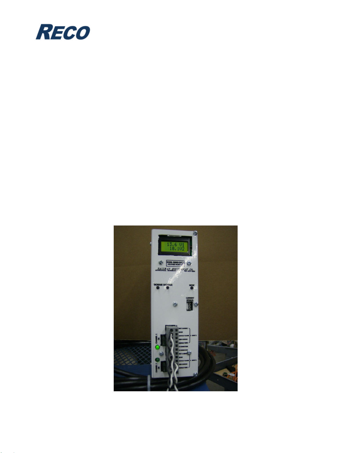
The idle screen displays the input voltage. If only channel 1 has input voltage, only channel
1 will be displayed. If both channels are monitoring voltage sources, both will be displayed.
If the optional current or temperature probes are being used, the lower screen will alternate
between displaying channel 2 voltage, temperature, and current. With only channel 1
powered, the following screens will be scrolled through when the MODE button is
depressed:
PASSWORD ___- The password to adjust parameters is 5. It is entered by pressing the
INCREASE button until 5 appears in the parameter field.
MAX VCH1
SET __._ - This displays the high voltage setpoint parameter for channel 1. It can be
adjusted from 0 to 50.0 VDC by use of the INCREASE or DECREASE push buttons. If the
input voltage rises above the setpoint, the channel 1 output relay will change state and the
channel 1 CHANNEL OK LED will go out. Factory default is 50.0 VDC.
LOW VCH1
SET __._ - Low voltage setpoint for channel 1, adjustable from 0 to 50.0 VDC.
If the input voltage falls below the setpoint, the output relay will change state and the
CHANNEL OK LED will go out. Factory default is 0 VDC.
DELAY CH1
SET ___ - Delay time in seconds before a voltage falling outside the parameters will
trigger a fault. This parameter is adjustable from 1 to 600 seconds. Factory default is 10
seconds.
If a voltage input is added on channel 2, in addition to the input on channel 1, the following
additional screens to appear as the MODE button is used:
MAX VCH2
SET __._ -High voltage setpoint for channel 2. Voltage range is 0 to 150.0 VDC
Factory default is 150.0 VDC.
LOW VCH2
SET __._ - Low voltage setpoint for channel 2. Voltage range is 0 to 150.0 VDC.
Factory default is 0 VDC.
DELAY CH2
SET ___ - Delay time in seconds for channel 2. Range is 0 to 600 seconds.
Factory default is 10 seconds.
There is an optional amp probe available which can be set up to trip the same relay as a
voltage fault will trip on Channel 2. The addition of the current probe will cause the
following additional screens to appear:
HIGH AMP
SET ___ - Parameter for amp setting above which channel 2 will change relay State.
Amp range is -120 to +120 amps. Factory default is +120 amps.

Voltage Monitor – Instruction Manual
Model 520603-2V150
P/N 520603-2V150 • REV. D, 8/31/21 • © RAILWAY EQUIPMENT CO.
5
LOW AMP
SET ___ - Amp setting below which channel 2 will trip. Amp range is -120 to +120 amps.
Factory default is -120 amps.
There is also an optional temperature probe that can control the channel 2 output. If the
probe is used, the temperature can be displayed as Fahrenheit or Celsius. To select either
Fahrenheit or Celsius, enter 10 on the PASSWORD screen. With 10 as your password,
two additional screens will show up as the parameter screens are toggled through. One
screen is: F OR C _____. The INCREASE or DECREASE buttons can be used to select
which temperature scale will be displayed. The next screen will be REV. LEV ______.
This screen will display the software revision level installed on the monitor. The addition of
the temp probe adds the following screens:
HIGH TEMP
SET ___ - Temperature setting above which channel 2 relay will change state.
Available temperature range is -40°F to +300°F (-40°C to 148.9°C). Factory default is
+300°F (148.9°C).
LOW TEMP
SET ___ - Temperature setting below which channel 2 relay will change state. Available
temperature range is -40°F to +300°F (-40°C to 148.9°C). Factory default is -40°F (-40°C).
The following Fault Counter Screens will appear only if the fault count in each is
Greater than 0:
CH 1 HI V
COUNT ___ - Number of high voltage incidents on Channel 1. Press DECREASE to clear.
CH 1 LO V
COUNT ___ -Low voltage incidents on Channel 1. Press DECREASE to clear.
CH 2 HI V
COUNT ___ - High voltage incidents on Channel 2. Press DECREASE to clear.
CH 2 LO V
COUNT ___ - Low voltage incidents on Channel 2. Press DECREASE to clear.
HI TEMP
COUNT ___ - High temperature incidents on Channel 2. Press DECREASE to clear.
LOW TEMP
COUNT ___ - Low temperature incidents on Channel 2. Press DECREASE to clear.
HI AMP
COUNT ___ - High amperage incidents on Channel 2. Press DECREASE to clear.
LOW AMP
COUNT ___ - Low amperage incidents on Channel 2. Press DECREASE to clear.

Voltage Monitor – Instruction Manual
Model 520603-2V150
P/N 520603-2V150 • REV. D, 8/31/21 • © RAILWAY EQUIPMENT CO.
6
4.2 Push Buttons
Below the digital display are three control push buttons:
INCREASE – This is used to increase the value of the displayed parameter, if enabled.
DECREASE – This button will decrease the value of the displayed parameter, if enabled.
MODE – This control is used to increment through the available screens.
4.3 LED Status Indicators
Two LEDs are used to indicate Channel OK, one for each input channel.
4.4 External Wiring Connector
Near the bottom of the front panel there is a twelve position socket with a removable
connector for external wiring. The connection locations are shown below:
PIN CONNECTION VOLTAGE INPUT NUMBER
12 INPUT 10-48 VDC # 1 +VOLTAGE
11 COM 0V # 1 -VOLTAGE
10 NORMALLY CLOSED # 1 OUTPUT RELAY
9FUSED COMMON # 1 OUTPUT RELAY
8NORMALLY OPEN # 1 OUTPUT RELAY
7NO CONNECTION
6NO CONNECTION
5INPUT 1-150 VDC # 2 + VOLTAGE
4COM 0V # 2 – VOLTAGE
3NORMALLY CLOSED # 2 OUTPUT RELAY
2FUSED COMMON # 2 OUTPUT RELAY
1NORMALLY OPEN # 2 OUTPUT RELAY
4.5 Current Sensor
The current sensor connector is located on the right center of the front panel. The sensor is
optional, consisting of a plug end wired to a split current coil that can monitor the current
level of a circuit monitored by channel 2. By setting the current parameters, the current
level can be used to trigger a fault condition on channel 2, either independently, or in
conjunction with channel 2 voltage, and/or with the temperature sensor.

Voltage Monitor – Instruction Manual
Model 520603-2V150
P/N 520603-2V150 • REV. D, 8/31/21 • © RAILWAY EQUIPMENT CO.
7
4.6 Temperature Sensor
On the top of the monitor case is a temperature sensor jack. The temp sensor is an
optional thermocouple that can be placed to monitor battery, equipment, or air temperature.
By setting the temp parameters, the temperature level can be used to trigger a fault
condition on channel 2, either independently, or in conjunction with channel 2 voltage,
and/or with the current sensor.
5. REMOTE MONITORING
With the addition of a communications board, the Voltage Monitor can be remotely monitored
via the Ethernet port. This requires the Voltage Monitor to be connected to the internet and a
paid subscription from Railway Equipment Company.
5.1 Status Page
The Status page shows the current status of the charger, consisting of Module Indicators,
Faults, Fault Counters, Readings and Settings.
Figure 2. Status Screen

Voltage Monitor – Instruction Manual
Model 520603-2V150
P/N 520603-2V150 • REV. D, 8/31/21 • © RAILWAY EQUIPMENT CO.
8
5.2 History Page
The History page shows any historical data that has been transmitted to our servers. The
graph is interactive, which allows you to select specific date ranges, zoom in/out and
add/remove data pens.
Figure 3. Historical graphing of Voltages, Current and Temperature
5.3 Configuration
The Ethernet port by default is setup to communicate to the remote monitoring servers. If
these settings need to be changed, the section below describes how to change these.
PASSWORD
15 - The password to adjust parameters is 15. It is entered by pressing the
INCREASE button until 15 appears in the parameter field.
Ixxx.xxx
.xxx.xxx – This displays the IP address of the Voltage Monitor. This cannot be changed from
this screen.
Sxxx.xxx
.xxx.xxx – This displays the Server IP address that the Voltage Monitor will communicate with.
By default this should be set to 208.42.179.9.

Voltage Monitor – Instruction Manual
Model 520603-2V150
P/N 520603-2V150 • REV. D, 8/31/21 • © RAILWAY EQUIPMENT CO.
9
DHCP IS
ENABLED – Enable or Disable DHCP. By default this is set to Enabled, which will require the
Voltage Monitor to acquire and IP address from a DHCP server.
IP LB
xxx… – Configures the first 3 digits of the IP address. This cannot be changed if DHCP is set
to Enabled.
IP HB
. xxx.. – Configures the second 3 digits of the IP address. This cannot be changed if DHCP is
set to Enabled.
IP UB
.. xxx. – Configures the third 3 digits of the IP address. This cannot be changed if DHCP is set
to Enabled.
IP MB
… xxx – Configures the last 3 digits of the IP address. This cannot be changed if DHCP is set
to Enabled.
SUB LB
xxx… – Configures the first 3 digits of the Subnet Mask. This cannot be changed if DHCP is
set to Enabled.
SUB HB
. xxx.. – Configures the second 3 digits of the Subnet Mask. This cannot be changed if DHCP
is set to Enabled.
SUB UB
.. xxx. – Configures the third 3 digits of the Subnet Mask. This cannot be changed if DHCP is
set to Enabled.
SUB MB
… xxx – Configures the last 3 digits of the Subnet Mask. This cannot be changed if DHCP is
set to Enabled.
GATE LB
xxx… – Configures the first 3 digits of the Gateway. This cannot be changed if DHCP is set
to Enabled.
GATE HB
. xxx.. – Configures the second 3 digits of the Gateway. This cannot be changed if DHCP is
set to Enabled.
GATE UB
.. xxx. – Configures the third 3 digits of the Gateway. This cannot be changed if DHCP is set
to Enabled.
GATE MB
… xxx – Configures the last 3 digits of the Gateway. This cannot be changed if DHCP is set
to Enabled.

Voltage Monitor – Instruction Manual
Model 520603-2V150
P/N 520603-2V150 • REV. D, 8/31/21 • © RAILWAY EQUIPMENT CO.
10
PDNS LB
xxx… – Configures the first 3 digits of the Primary DNS. This cannot be changed if DHCP is
set to Enabled.
PDNS HB
. xxx.. – Configures the second 3 digits of the Primary DNS. This cannot be changed if DHCP
is set to Enabled.
PDNS UB
.. xxx. – Configures the third 3 digits of the Primary DNS. This cannot be changed if DHCP is
set to Enabled.
PDNS MB
… xxx – Configures the last 3 digits of the Primary DNS. This cannot be changed if DHCP is
set to Enabled.
SDNS LB
xxx… – Configures the first 3 digits of the Secondary DNS. This cannot be changed if DHCP
is set to Enabled.
SDNS HB
. xxx.. – Configures the second 3 digits of the Secondary DNS. This cannot be changed if
DHCP is set to Enabled.
SDNS UB
.. xxx. – Configures the third 3 digits of the Secondary DNS. This cannot be changed if DHCP
is set to Enabled.
SDNS MB
… xxx – Configures the last 3 digits of the Secondary DNS. This cannot be changed if
DHCP is set to Enabled.
WEB PORT
xxxxx – Configures the port on the Server that the Voltage Monitor communicate with. By
Default this is set to 49153.
LOC PORT
xxxxx – Configures the port on the Voltage Monitor that the Server communicates to. By
Default this is set to 10089.
6. DRAWINGS

This manual suits for next models
1
Table of contents
Other RECO Measuring Instrument manuals
Popular Measuring Instrument manuals by other brands

Luzchem
Luzchem SPR-02 instruction manual

Victor
Victor 5005 instruction manual

Rohde & Schwarz
Rohde & Schwarz R&S ZNBT Getting started

Circutor
Circutor MD-5060 Technical specifications and operating instructions

DKK-TOA
DKK-TOA MBM-162 instruction manual

Keysight Technologies
Keysight Technologies BT2152A Operating and service guide