Entes DCA-10 User manual
A4741 / Rev.1 www.entes.com.tr
DC AMMETER
DCA-10 / 10A / 10C / 10S / 10CS / 11 / 11A / 11C / 11S / 11CS
User Manual and Menu Map

2
1
Displayed
only when
limit is
crossed in
opposite
direction.
Read the user manual completely before using the device.
The box is under dangerous high voltage. The device must be installed and serviced only by
a qualified service personnel.
Is not displayed when
limit is crossed in
opposite direction.
If a current higher than the defined current value flows through the shunt
resistor, a warning is displayed like the one on the left.
H CURRENT
Warnings
-Connect a button or a circuit breaker between the grid and the supply inputs of the device.
- This button or circuit breaker must be in close proximity of the device.
-This button or circuit breaker must be marked to indicate that it is used to separate the device from
the grid.
Standards That Are Applied To The Device
EN 61010-1, EN 60255-5, EN 60255-22-5, EN 60255-22-4, EN 60255-22-2, EN 60255-11, EN 60255-22-3
Guarantee
The device has a 2 year guarantee. In case of a malfunction, repairs of the device must be done only by
the authorised technical service or the guarantee will be void.
1. INTRODUCTION............................................................................................1
1.1. APPLICATIONS..................................................................4
1.2. GENERAL FEATURES...........................................................4
1.3. FRONT PANEL.....................................................................5
1.4. HARDWARE FEATURES......................................................7
2. USAGE OF DEVICE......................................................................8
2.1. MENU USAGE AND SETTINGS..........................................8
2.2. MAIN MENUS.....................................................................8
2.2.1. SHUNT MENU.............................................................10
2.2.2. PERIOD SETTING MENU.............................................11
2.2.3. ALARMS MENU............................................................11
2.2.4. ANALOG OUTPUT SETTING MENU............................19
Index
ATTENTION
- Disconnect all power before connecting the device.
-Dont remove the front panel while the device is connected to the network.
-Dont clean the device with solvent or similar substances. Only clean with a dry cloth.
- Verify correct terminal connections when wiring.
- Electrical devices should be serviced only by your component seller.
- Device is for rack panel mounting only.
-Fuse which will be used must be F type and its current limit value must be 1A.
-No responsibility is assured by the manufacturer or any of its subsidiaries for any problems
arising out of the disregard of these conditions.
SECURITY

34
2.2.5. RS-485 SERIAL COMMUNICATION SETTING MENU..........21
2.2.6. RESET MENU.................................................................25
2.2.7. DISPLAY SETTING MENU...............................................26
2.2.8. LANGUAGE SETTING MENU..........................................27
2.2.9. FACTORY SETTING MENU.............................................28
2.2.10. SECURITY SETTING MENU................................................29
2.2.11. LEAVING THE MAIN MENU............................................30
3. INSTALLATION..........................................................................................31
3.1. DIMENSIONS AND INSTALLATION........................................31
3.2. CONNECTION DIAGRAM..........................................................32
3.3. PC CONNECTION....................................................................33
4. FACTORY DEFAULT VALUES.......................................................34
5. TECHNICAL FEATURES......................................................................36
6. REGISTER TABLE..........................................................................38
7. MENU MAP..................................................................................46
1.INTRODUCTION
1.1.APPLICATIONS:
You can achieve the following measurements and applications with the device.
- Current values of various DC systems can be measured with adjustable shunt current and voltage values.
- All measured parameters can be transferred via RS485 line with MODBUS protocol and menu settings
can be set remotely. (DCA-10S/10CS/11S/11CS)
-With 2 programmable Alarm Relays, a range in which the monitored system current should reside can be
determined and a warning signal can be created for the user with Alarm1 (C1) and Alarm2 (C2) contact
outputs if this monitored current goes out of the determined range. (DCA-10C/10CS/11C/11CS)
- With a programmable Analog Output, the device can be programmed to give a voltage or current output
according to the measured current value. (DCA-10A/11A)
-Measured maximum-minimum values can be monitored by using UP/DOWN buttons.
-Settings can be accessed easily and read comfortably with the back-lit LCD feature.
- Measurement results can be calculated in a desired time with an adjustable measurement period of 1-
600 s.
-The device provides flexible usage with wide supply voltage range. 85-265 V AC/DC
(DCA-10/10A/10C/10S/10CS), 10-56V DC (DCA-11/11A/11C/11S/11CS )
- The device settings can be protected from changes by unauthorized personnel by specifying a 4 digit
user password.
1.2 GENERAL FEATURES
The device is designed to measure the current on a DC system through an externally connected shunt
resistor.
5 6
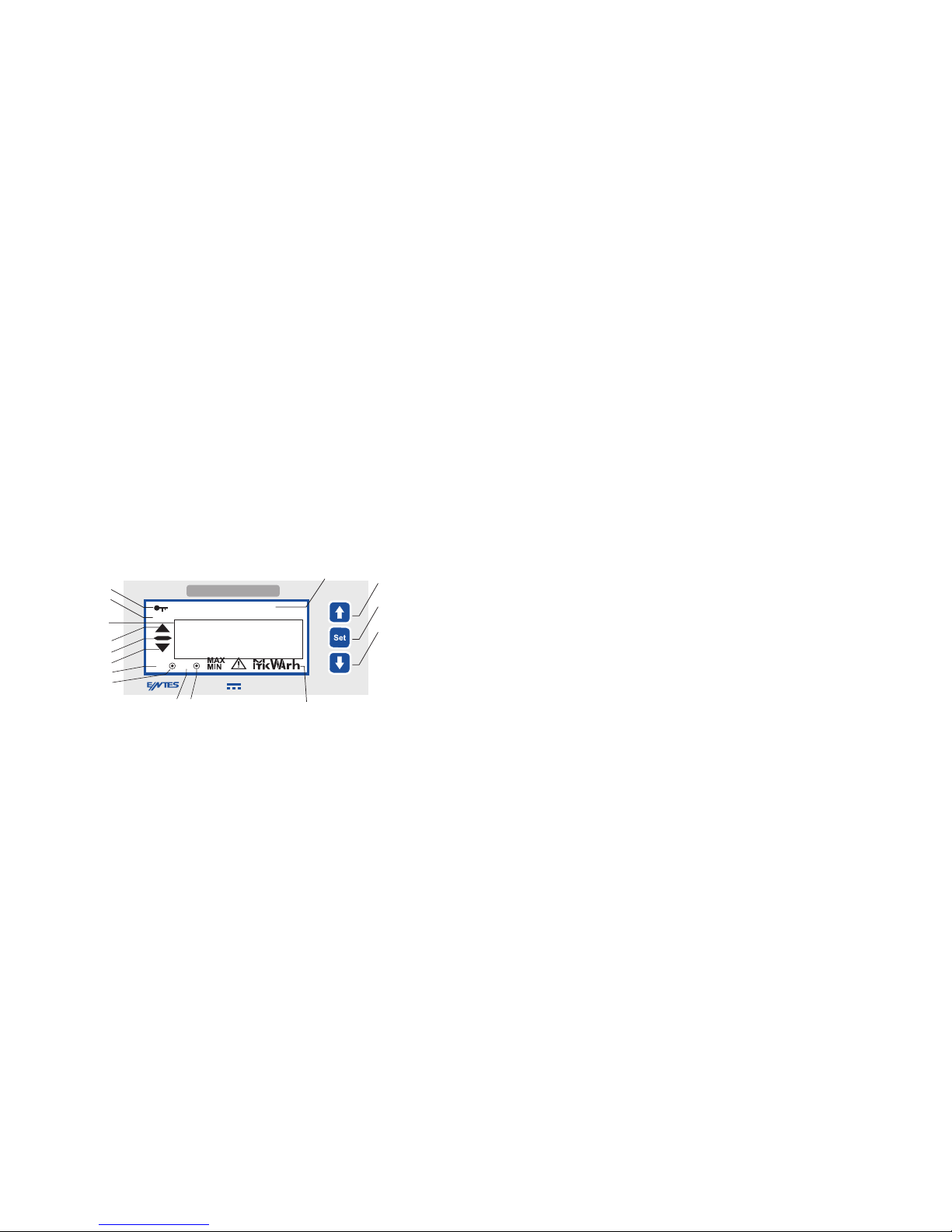
1.3 FRONT PANEL
The device has a back-lit 2.5 LCD which contains two lines as numeric and alpha-numeric, warning
symbols and notification signs. There are three buttons for programming the device. Explanations
about the display and buttons are listed on the right side.
Usage of Front Panel and Buttons
1. Up button
2. Set button, for entry to menu and value entry
3. Down button
4. Indicates that the password protection is active.
5. Indicates the existence of communication. It blinks during communication. (DCA-10S/10CS/11S/11CS)
6. The line where measured parameters are displayed.
7. Indicates the direction of the measured voltage.
8. Indicates the notification messages or the menu where the user is.
9. Units belonging to measurements and analog output parameters.
10. Indicates that the contact or contacts are in a high fault state. When entering a value in High Alarm type,
it lights up continuously. When entering a low value for Range Alarm type, it lights up continuously and
when entering a high value for Range Alarm type, it blinks.(DCA-10C/10CS/11C/11CS)
11. Indicates that the contact or contacts are in a low fault state. When entering a value in Low Alarm type,
it lights up continuously. When entering a high value for Range Alarm type, it lights up continuously and
when entering a low value for Range Alarm type, it blinks.(DCA-10C/10CS/11C/11CS)
12. 1st Contact Output (DCA-10C/10CS/11C/11CS)
13. 2nd Contact Output (DCA-10C/10CS/11C/11CS)
14.15. Indicates that the contacts are closed.(DCA-10C/10CS/11C/11CS)
DCAMMETER
C1 C2
Rx/Tx %
PASSWORD
88888
A
DCA-10S
4
5
6
81
2
3
9
7
10
11
12
14
13 15

78
Special Functions for Buttons
UP button: In monitoring mode, it is used to display the maximum current value.
In program mode, it is used to change the device parameters.
SET button: When it is pressed for 3 seconds, the user enters MAIN MENU. It is then used to
enter SUB MENUs from the MAIN MENU and to save the changes in parameters.
If Latch function is active, it opens the alarm output contacts when the system
current leaves the programmed range. When the current enters the programmed
range, alarm output contacts dont close (lock-hold). Output contacts are closed
by using the SET button.
DOWN button: In monitoring mode, it is used to display the minimum voltage value.
In program mode, it is used to change the device parameters.
1.4 HARDWARE FEATURES
- Current measurement connector (2-pin, I+, I-)
- 0/2-10V, 0-4/20 mA Analog Output connector (3-pin, V, GND, I)(DCA-10A/11A)
- RS-485 connector (4-Pin)(DCA-10S/10CS/11S/11CS)
- 2 Relay connectors ( 4-pin)(DCA-10C/10CS/11C/11CS)
- Supply input (2-pin) (85-265V AC/DC (DCA-10/10A/10C/10S/10CS),
10-56V DC (DCA-11/11A/11C/11S/11CS))
2- USAGE OF DEVICE:
2.1 MENU USAGE AND SETTINGS:
After the device is installed according to the connection diagram in the user manual, energise the
device.(Refer to: Connection diagram)
In order for the measurements and applications to be accurate, necessary adjustments must be made
by using menus.
2.2 MAIN MENUS:
There are 10 main menus on the device for measurement and usage settings. The user can access
MAIN MENUs by pressing the SET button for 3 seconds on measurement screen. By pressing the SET
button on any MAIN MENU, SUB MENUs of the related MAIN MENU is entered.
Note: In order for a change that you committed in the menu to be in effect, you must give approval
for those changes when exiting the menu. Otherwise, changes will not be in effect.

2.2.1 SHUNT MENU
Current and voltage values of the external shutn resistor which will be connected to the device to
measure the current is set in this menu. There are 2 submenus under SHUNT menu.
SHUNT C, SHUNT V.
SHUNT C Shunt Current Setting Menu
The current value of the shunt resistor which will be connected to the device is entered in this menu.
Shunt current can be entered between 1A and 10000A (10 kA). When this parameter is changed,
maximum and minimum current values stored up until that time are deleted.
Note: The shunt that you will connect to the system must have a current characteristic 1.5 times than
the current need of your system. Example: If your current need is 100A, the minimum current value of
the shunt that you will connect must be 150A.
If you connect a 100A shunt to a 100A system, it may cause the shunt to burn up over time. Additionally;
in order for the shunt to be compatible with the measuring class of the device, it must be minimum 0.5%
class. Otherwise, you cant obtain a 0.5% accuracy with the measurements made with the device.
10
BACK MENUSHUNT VSHUNT CSHUNT C V
SET
SET
00100 150
AmV
SHUNT C SHUNT C
0100
SHUNT C
SET
0005 00050
SET SET
00100
A
SHUNT C
A
9
MAIN MENU FLOW
001.00
Only valid for
DCA-10C/10CS/
11C/11CS.
Only valid for
DCA-10A/11A.
Only valid for
DCA-10S/10CS/
11S/11CS.
RESETDISPLYSETLANGUAGE
ENG
FCTRY SETSECURITY
ESCAPE
RS 485
SHUNT C V PERIOD
001
ALARMS ANLG OUT
NO
SET
Press for 3 seconds.
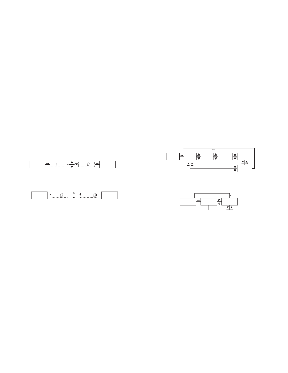
SHUNT V Shunt Voltage Setting Menu
The voltage value of the shunt resistor which will be connected to the device is entered in this menu.
Shunt voltage can be entered between 50mV and 150mV. When this parameter is changed, maximum
and minimum current values stored up until that time are deleted.
SHUNT V
50
SHUNT V
SET
05 050
SET SET
150
SHUNT V SHUNT V
mV mV
11 12
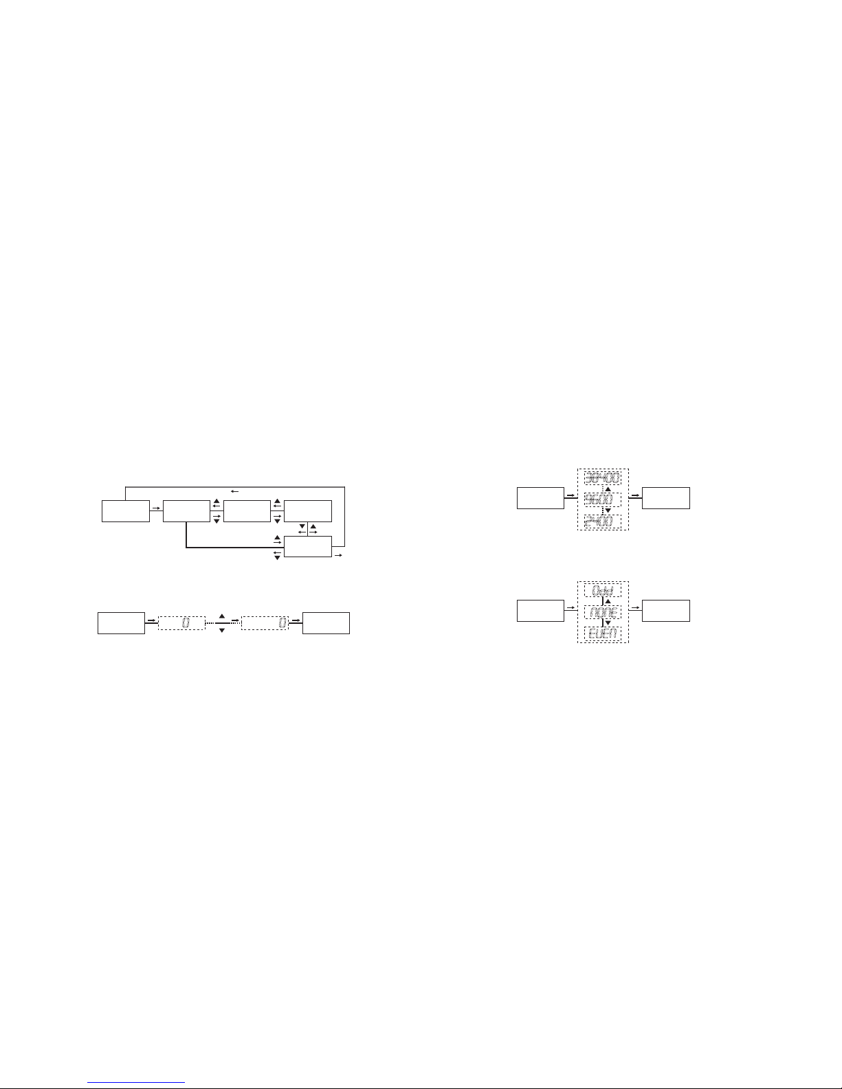
ALARMS
SET
ALARM 1
SET
TRIPALARM 2
NO
LATCH
NO
BACK MENU
2.2.2 PERIOD Period Setting Menu
After the device samples for a specified time, it displays the measurement result by calculating the
mean value of those samples. You can set the sampling time in this menu. Period value can be entered
between 1-600 seconds.
PERIOD
PERIODPERIOD
01
PERIOD
SET
001 05 050
SET SET
2.2.3 ALARMS Alarms Menu
DCA -10C/10CS/11C/11CS devices have two normally open (NO) contact outputs. Operating modes
of the alarms are set in this menu. Each alarm can be set to one of six operating modes. These modes
are high alarm, low alarm, high-low (range) alarm and their 3 inverted counterpart modes. This menu
has 4 sub-menus.
ALARM1, ALARM2, TRIP, LATCH.
ALARM1Alarm 1 Setting Menu
Operating mode of the relay on the device and the parameter according to that operating mode is set
in this menu. All settings belonging to 1. Alarm relay is done in this menu. Settings belonging to 2nd
Alarm relay can be done in ALARM2 menu. This menu has 1 sub-menu.
ALARM 1
SET
ALRM STAT BACK MENU
SET

14
When the alarm type is selected as High Alarm, first contact output opens after an on-delay time (H ON
DEL) if the measured current becomes more than the entered maximum current value (HGH VALUE) and
immediate opening option is inactive. In this case, up segment on the LCD and the dot in the C1 segment
turn on. When the measured current drops below the set maximum value (HGH VALUE) as much as the
high hysteresis value (HIGH HYS) and immediate opening option is inactive, first output contact closes
after an off-delay time (H OFF DEL). In this case, up segment on the LCD and the dot in the C1 segment
turn off.
13
CONTC POS SET
OFF
CONTC POS
CONTC POS
ON
SET
ALRM STAT SET
SET
SET
OFF
ALRM STAT
CONTC POS
OFF
ALRM TYPE
HIGH
BACK MENU SET
"ALRM STAT" Alarm Status Setting Menu
Alarm function of the relay is activated in this menu. If "OFF" option is selected in this menu, alarm
parameters of the corresponding relay cant be accessed. If the alarm function will be used, "ALRM
STAT" option must be set as "ON" in this menu. When alarm status is set as ON, the 2 sub-menus
of this menu become accessible. These menus are "CONTC POS" and "ALRM TYPE" menus.
CONTC POS Contact Position Setting Menu
The starting position of the alarm relay output is set in this menu. If this option is selected as OFF,
contact output starts as open when there isnt a fault condition. If this option is selected as ON, contact
output will be closed when there isnt a fault condition. It is set OFF as factory default.
ALRM TYPE Alarm Type Setting Menu
Operating mode of the alarm is set in this menu. Alarm has 3 operating modes which are High, Low and
Range (High-Low).
ALRM TYPE
ALRM TYPE SET
HIGH
ALRM TYPE
LO
SET

15 16
When the alarm type is selected as Low Alarm, first contact output opens after an on-delay time (L
ON DEL) if the measured current becomes less than the entered minimum current value (LOW
VALUE) and immediate opening option is inactive. In this case, down segment on the LCD and the
dot in the C1 segment turn on. When the measured current rises above the set minimum value (LOW
VALUE) as much as the low hysteresis value (LOW HYS) and immediate opening option is inactive,
first output contact closes after an off-delay time (L OFF DEL). In this case, down segment on the
LCD and the dot in the C1 segment turn off.
When the alarm type is selected as High-Low Alarm (Range), LOW VALUE operates as low alarm
and HGH VALUE operates as high alarm. While this alarm type is selected, minimum current value
(LOW VALUE) cant be entered higher than maximum current value (HGH VALUE).
H ON DEL
It is the delay time for the high current alarm to activate. The value is entered as seconds. It can be
entered between 000.0 and 999.9 seconds.
H ON DEL
50.0
H ON DEL
SET
005. 005.0
SET SET
050.0
H ON DEL H ON DEL
HIGH ALARM
HGH VALUE
The highest value that you want the measured current to reach is entered in this menu. A value between
-/+ Shunt Current can be entered. If the value is entered as 0 (zero), high alarm is deactivated.
HGH VALUE
00
HGH VALUE
SET
05 050
SET SET
100
HGH VALUE HGH VALUE
A A
HIGH HYS
Return value (to the normal operation) from the high current fault which is the hysteresis current value
is entered in this menu. A value between 0...Shunt Current/2 can be entered.
HIGH HYS
50
HIGH HYS
SET
03 030
SET SET
050
HIGH HYS HIGH HYS
A A
H OFF DEL
It is the delay time for the high current alarm to deactivate. The value is entered as seconds. It can be
entered between 000.0 and 999.9 seconds.
H OFF DEL
H OFF DEL
SET SET SET
H OFF DEL H OFF DEL
50.0 005. 005.0
050.0
LOW ALARM
LOW VALUE
The lowest value that you want the measured current to reach is entered in this menu. A value between
-/+ Shunt Current can be entered. If the value is entered as 0 (zero), low alarm is deactivated.
LOW VALUE
00
LOW VALUE
SET
05 050
SET SET
100
LOW VALUE LOW VALUE
A A

17 18
TRIP
If the measured current value becomes more than 1.5 times of set maximum current value when the
TRIP function is selected as YES, related alarm contact will open without a delay. In this case,
up segment on the LCD and the dot in the C1 segment turn on. If the measured current value becomes
less than 0.5 times of set minimum current value, related alarm contact will open without a delay. In
this case, down segment on the LCD and the dot in the C1 segment turn on.
TRIP SET
NO
TRIP
TRIP
YES
SET
LOW HYS
Return value (to the normal operation) from the low current fault which is the hysteresis current value
is entered in this menu. A value between 0...Shunt Current/2 can be entered.
LOW HYS
50
LOW HYS
SET
03 030
SET SET
050
LOW HYS LOW HYS
A A
L ON DEL
It is the delay time for the low current alarm to activate. The value is entered as seconds. It can be
entered between 000.0 and 999.9 seconds.
D ON T
D ON T
SET SET SET
D ON T D ON T
50.0 005. 005.0
050.0
L OFF DEL
It is the delay time for the low current alarm to deactivate. The value is entered as seconds. It can be
entered between 000.0 and 999.9 seconds.
D OFF T
D OFF T
SET SET SET
D OFF T D OFF T
50.0 005. 005.0
050.0
LATCH
When the latch function is selected as YES, a predefined alarm contact will open in case an alarm
state arises. When the alarm state is resolved, the contact remains open (It latches). To close the
alarm outputs after the alarm state is resolved, SET button is pressed. When the latch function is
selected as NO, the opened alarm output will close after the predefined delay time.
LATCH SET
NO
LATCH
LATCH
YES
SET

19 20
2.2.4 ANLG OUT Analog Output Setting Menu
ANLG OUT
The device can give a voltage or current output with respect to the measured current according to your
selection. Analog output value can be selected as 0-10V, 2-10V, 0-20mA or 4-20mA. The user can set
the analog output type, turn off the analog output, learn the active analog output type or set the minimum
and maximum values which the device will take into consideration when generating an analog output.
ANLG OUT
SET
ANLG OUT
SET
mA
0-20
ANLG OUT
ANLG OUTANLG OUT ANLG OUT
SET SET SET SET
BACK MENU
HIGHEST
200
LOWEST
000
SET
mA mA V V
V V
HIGHEST
The current value corresponding to the maximum value of the selected analog output type is set in
this menu. This value can be entered between -/+ Shunt Current values.
Example: When the analog output type is selected as 0 - 20 mA and HIGHEST value is set as
100A, current value on the analog output will be 20 mA when the measured current becomes 100A.
LOWEST
The current value corresponding to the minimum value of the selected analog output type is set in
this menu. This value can be entered between -/+ Shunt Current values.
Example: When the analog output type is selected as 0 - 20 mA and LOWEST value is set as
10A, current value on the analog output will be 0 mA when the measured current becomes 10A.
LOWEST
00
LOWEST
SET
03 030
SET SET
000
LOWEST LOWEST
AA
HIGHEST
00
HIGHEST
SET
10
SET SET
200
HIGHEST
A
HIGHEST
100
A
21 22
2.2.5 RS-485 Serial Communication Setting Menu
All measured parameters can be transferred via RS485 line with MODBUS protocol and menus can be
set remotely.
Note: Communication feature is available only on DCA-10S/10CS/11S/11CS models. In order for the
communication to be accomplished; Address, Baudrate and Parity values must be entered to the device
correctly. RS 485 menu has 3 sub-menus. ADDRESS , BAUDRATE , PARITY.
ADDRESS Address Setting
Address information can be entered between 1 and 247.
ADDRESS
ADDRESSADDRESS
01
ADDRESS
SET
001 03 030
SET SET
PARITYBAUDRATE
9600
ADDRESS
001
RS-485
SET
BACK MENU
NONE
SET PARITY Parity Setting
Parity can be entered as none, odd or even.
BAUDRATE Baudrate Settings
Enter one of the 2400 bps, 4800 bps, 9600 bps, 19200 bps, 38400 bps values as stated in the
communication software.
BAUDRATE
BAUDRATE
BAUDRATE SET
9600 9600
SET
Selected
parameter
is
displayed
PaRITY
PaRITY
PaRITY SET
NONE EVEN
SET
Selected
parameter
is
displayed

23 24
Read Hold (03H) function is used for reading the measured parameter (intantenaous measurement
value, minimum and maximum measurement values) and other setting values of the device. If any
register other than this area has been tried to reead, the device will send an error message.
For example; below message can be sent to read the measured current value:
Preset Single Register (06H) function is used for change device settings (shunt voltage/current etc.) and
resetting the measured minimum/maximum values.
For example; below message can be sent to set the shunt voltage value to 100:
Preset Multiple register (10H) function is used for changing more than one register value.
For example; below message can be sent to set the shunt voltage and shunt current values to 100:
Read device info (2BH) function is used to learn the manufacturer name, the device code, hardware version
and software version. The query packet to read the device info is as following:
01 2B 0E 01 00 70 77
MODBUS RTU PROTOCOL
Standart MODBUS RTU message is shown below.
TADDRESS
8 BIT
FUNCTION
8 BIT
DATA
N x 8 BIT CRCH CRCL T
Modbus Functions:
The T times corresponds to a time in which data must not be exchanged on the communication bus
to allow the connected devices to recognize the end of one message and the beginning of another.
This time must be at least 3.5 characters at the selected baud rate. Adress range (1-247) is address
of the connected device. The data field contains data sent to the slave by master or data sent to
master by slave. CRC is a error check method by using MODBUS RTU protocol and consists of 2
bytes.
03H READ HOLD REGISTERS
06H PRESET SINGLE REGISTER
10H PRESET MULTIPLE REGISTERS
2BH READ DEVICE INFO
01
Device
Address
03
Function
40
MSB
Address
00
LSB
Address
00
Register
number
MSB
01
Register
number
LSB
91
CRC
MSB
CA
CRC
LSB
E1
CRC
LSB
01
Device
Address
06
Function
80
MSB
Address
00
LSB
Address
00
Data
MSB
64
Data
LSB
A1
CRC
MSB
01
Device
Address
10
Function
80
MSB
Addr.
00
LSB
Addr.
00
Register
number
MSB
02
Register
number
LSB
04
Byte
count
00
Data
MSB
64
Data
LSB
00
Data
MSB
64
Data
LSB
D2
CRC
MSB
ED
CRC
LSB

25 26
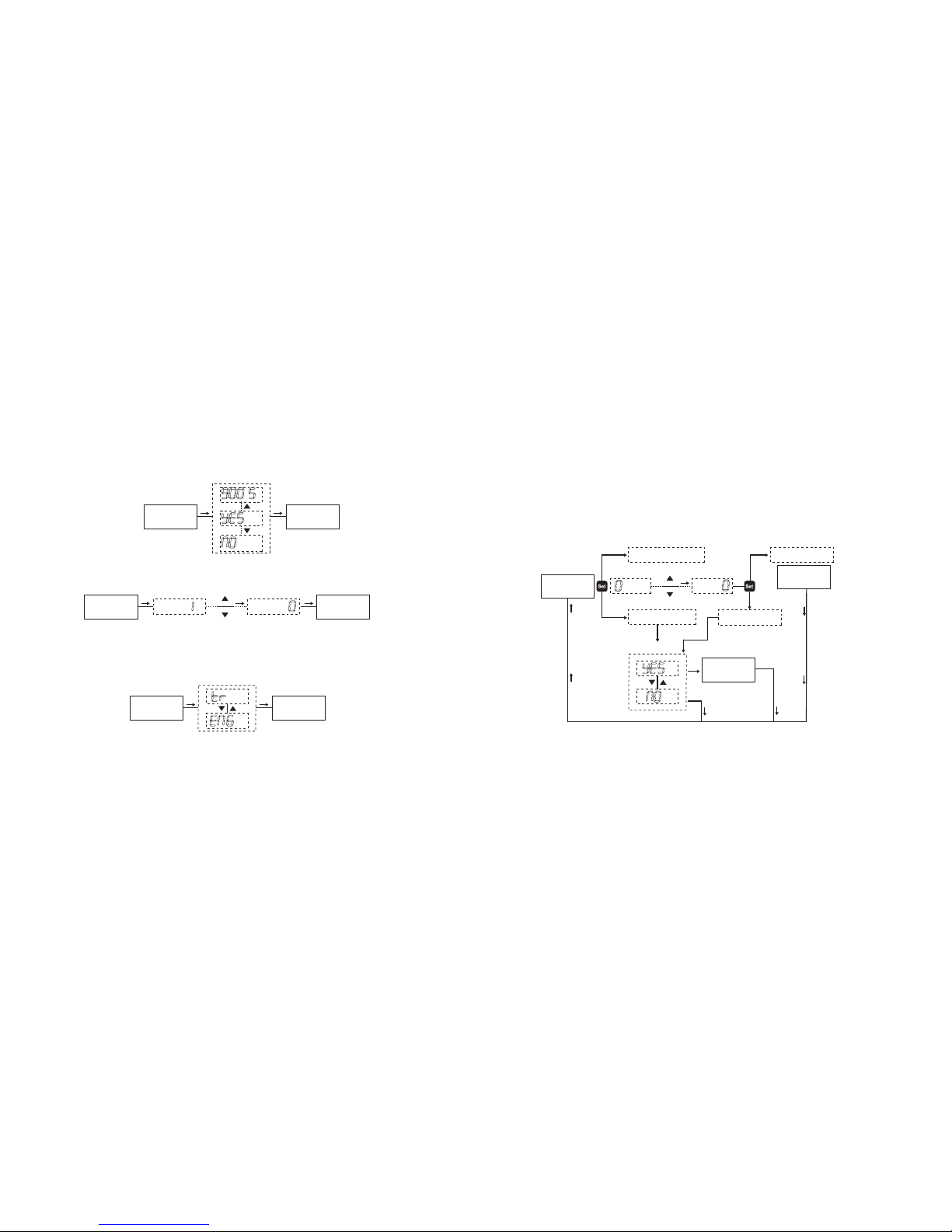
BACKLIGHT LCD Backlight Setting Menu
Backlight feature of the device is configured in this menu. Available choices are as following: NO Off.
YES Continuously on. "30 s" On for 30 seconds, "60 s" On for 1 minute, "300 s" On for 5 minutes, "900
s" On for 15 minutes. Backlight turns off after the selected time if no button is pressed at the end of that
time.
2.2.6 RESET Reset Menu
Minimum and maximum values among measured current values are stored on the device. Reset menu
is used in order to delete these values. There are 2 sub-menus under Reset menu: RESET MIN, RESET
MAX. To see the measured minimum and maximum values, refer to the Special Functions for Buttons
section of this user manual.
NOTE: Stored values are not affected from power outages. After you select YES option under the value
that you want to reset and approve the changes when you exit or a zero (0) value is written into the
addresses that these values are stored, measured minimum and maximum values are deleted.
BACK MENURESET MAXRESET MINRESET
SET
SET
RESET MAX Maximum Value Reset Menu
It is the menu where stored maximum current value is deleted.
RESET MIN Minimum Value Reset Menu
It is the menu where stored minimum current value is deleted.
RESET MAX
RESET MAX
RESET MAX
SET SET
RESET MIN
RESET MIN
RESET MIN
SET SET
2.2.7 DISPLYSET Display Setting Menu
Settings about the device display are done in this menu. Display setting menu has 2 sub-menus:
BACKLIGHT, CONTRAST.
BACK MENU
CONTRAST
15
BACKLIGHT
YES
DISPLYSET SET
SET
27 28
BACKLIGHT
BACKLIGHT
BACKLIGHT SET
30 S
SET
Selected
parameter
is
displayed.
YES
CONTRAST Contrast Setting Menu
Contrast of the device display is set in this menu. It can be set to a value between 00 and 15.
2.2.8 LANGUAGE Language Setting Menu
Language of the device is set in this menu. There are 2 language options as Tr Turkish and Eng
English.
CONTRAST
CONTRASTCONTRAST
5
CONTRAST SET
15 110
SET SET
DIL
LANGUAGE
LANGUAGE
SET SET
TRENG
2.2.9 FCTRY SET Factory Setting Menu
Factory settings are loaded in this menu. A 4 digit password is asked when entering this menu. If password
protection is active, the password isnt asked again when entering this menu because it was entered during
entering the main menu. If YES option is selected in this menu and SAVE confirmation is approved at the
exit of main menu, factory settings are loaded (Refer to: Factory Default Values).
FCTRY SET
FCTRY SET
ENTR PASSENTR PASS
000
SET
000
If password is inactive.
If password is active.
If password is wrong.
ENTR PASS
ERROR
SETTINGS
DONE
If password is correct.
SET
SET
NOTE: When factory settings are loaded, language setting stays unchanged. The language will be the same
as the on selected last.

29 30
2.2.10 SECURITY Security Setting Menu
Device password settings are done in this menu. There are 2 sub-menus under SECURITY menu.
PASS ACTV, PASS CHNG. Password activation and changing operations are done under these
menus. Factory default password is 0000.
BACK MENU
PASS CHNGPASS ACTVSECURITY SET
SET
NO
PASS ACTV Password Activation Menu
Password protection is activated or deactivated in this menu.
CHNG PASS Change Password Menu
Password is changed in this menu.
2.2.11 ESCAPE Exiting Main Menu
It is used to exit the main menu. If any changes has been made in the menus, a confirmation is asked to
save those changes. If there are no changes, measurement results are displayed without a confirmation.
SAVE
ESCAPE SET
SET
SET
Changes
are saved.
Changes
are
discarded.
024.00
MEASUREMENT
SCREEN
ACTVE
Selected
parameter
is
displayed.
PASS ACTV SET ENTR PASSENTR PASS
000
SET SET
000
PASS ACTV
PSIVE
SET
CHNG PASS SET OLD PASSOLD PASS
000
SET SET
000
NEW PASS
NEW PASS
000
SET
SET
REENTER
111
REENTER
SET SET
PAS CHNGD
111 000
A

31 32
3.2. CONNECTION DIAGRAM
85-265 V AC/DC
Un
+
14 15
-
+
12 13
-
Iin
RS-485
8 9 10 11
1A
RELAY 1
1 2 3 4 5 6 7
RELAY 2 V GND A
* **
TR B A GND
***
*****
********
+
-
DC
SOURCE
LOAD
ENTES
500 A 60 mV
Cl 0.5
* Only for DCA-10C/10CS/11C/11CS
** Only for DCA-10A/11A
*** Only for DCA-10S/10CS/11S/11CS
**** Only for DCA-11/11A/11C/11S/11CS
***** DCA-10/10A/10C/10S/10CS 85-265V AC/DC, DCA-11/11A/11C/11S/11CS 9-56V DC
Control Panel Area Dimensions
TYPE PR 20 (48x96)
48mm
96mm
Dimensions
43mm
54mm
Wall
50mm
TYPE PR 20 (48x96)
63mm
TYPE PR 20 (48x96)
44mm
91mm
Panel Cutout Dimensions
3. INSTALLATION
3.1. DIMENSIONS AND INSTALLATION
4. FACTORY DEFAULT VALUES:
Alarms:(DCV-10C/10CS/11C/11CS)
1.Alarm:
Alarm Status : Passive
Latch : Off
Trip : Off
Contact Position (Output Inverse) : Off
Alarm Type : High Alarm
High Alarm Value : 100A
Low Alarm Value : 10A
High Alarm Hysteresis : 10A
Low Alarm Hysteresis : 5A
High Alarm On Delay (d_on_time) : 20s
High Alarm Off Delay (d_off_time) : 10s
Low Alarm On Delay (d_on_time) : 20s
Low Alarm Off Delay (d_off_time) : 10s
2.Alarm:
Alarm Status : Passive
Latch : Off
Trip : Off
Contact Position (Output Inverse) : Off
Alarm Type : High Alarm
High Alarm Value : 100A
Low Alarm Value : 10A
High Alarm Hysteresis : 10A
Low Alarm Hysteresis : 5A
33 34
GND
GND
B
APC
...
REPEATER
MAX. 1200 mt. MAX. 1200 mt.
TR
B
A
...
RS-485 / RS-232
Converter
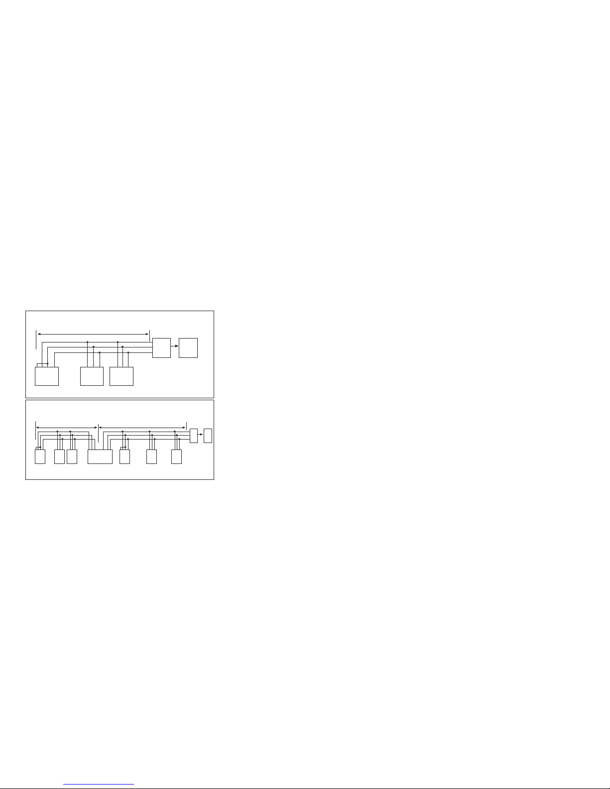
247 DEVICES CAN BE CONNECTED ON THE SAME LINE BY USING A REPEATER
DCA-10S/10CS -247.
DCA-11S/11CS -247.
DCA-10S/10CS -31.
DCA-11S/11CS -31.
DCA-10S/10CS -2.
DCA-11S/11CS -2.
DCA-10S/10CS -1.
DCA-11S/11CS -1.
3.3. PC CONNECTION
GNDTR B A GNDTR B A
GNDTR B A
GND
B
APC
...
DCA-10S/10CS -31.
DCA-11S/11CS -31.
MAX. 1200 mt.
RS-485 / RS-232
Converter
MAX. 31 DEVICES CAN BE CONNECTED ON THE SAME LINE
DCA-10S/10CS -2.
DCA-11S/11CS -2.
DCA-10S/10CS -1.
DCA-11S/11CS -1.

High Alarm On Delay (d_on_time) : 20s
High Alarm Off Delay (d_off_time) : 10s
Low Alarm On Delay (d_on_time) : 20s
Low Alarm Off Delay (d_off_time) : 10s
Shunt Parameters:
Shunt Current : 150A
Shunt Voltage : 150 mV
RS 485: (DCA-10S/10CS/11S/11CS )
Address : 1
Baudrate : 9600
Parity : None
Analog Output: (DCA-10A/11A)
Analog Output : 0 - 20 mA
Assign Hi : 200A
Assign Lo : 0A
Period : 1 (second)
Display
Backlight : On
Contrast : 15
Security
Password Protection : Off
Password : 0
35 36
5. TECHNICAL FEATURES:
Operating Voltage (Un) :85-265V AC/DC (DCA-10/10A/10C/10S/10CS),
10-56V DC (DCA-11/11A/11C/11S/11CS)
Frequency :50/60 Hz (DCA-10/10A/10C/10S/10CS)
Supply Input Power Consumption :< 4 VA
Measuring Input Power Consumption :< 1 VA
Measuring Input Resistance (Rin) :< 1K
Iin :+/- 150mV
Measuring Current Range :+/-10000A
Accuracy :0.5% ±1 Digit [(10% - 100%) x full scale]
Shunt Current :1A- 10000A (10kA)
Shunt Voltage : 50mV - 150mV
Relay Outputs (2 pieces) :2 NO, 5A 1250 VA (DCA-10C/10CS/11C/11CS)
Communication :MODBUS RTU (RS-485) Programmable.(DCA-10S/10CS/11S/11CS)
Baudrate :2400 - 38400
Address :1-247
Parity :None, Odd, Even
Analog Output :(DCA-10A/11A)
Analog Voltage Output :0-10 V or 2-10 V
Load Resistance :>= 1K2
Update Period :100ms (milliseconds).
Analog Current Output :0-20 mA or 4-20 mA
Load Resistance :<= 500ohm
Update Period :100ms (milliseconds).
Accuracy :±0.01 FS%
Period :1 - 600 seconds

37 38
Ambient Temperature : -20 ... 70°C
Display :2.5 inches Backlit LCD
Dimensions :PR-20
Device Protection Class :Double Insulation - Class II ( )
Casing Protection Class :IP 40
Terminal Protection Class :IP 00
Wire Width (For Terminals) : 2.5mm2
Casing Material :Nonflammable
Installation Type :Flush Mounting ( PR-20 )
Weight :0.240 kg
Installation Class :Class III
Panel Cutout Dimensions :48X96 mm (PR-20)
6. REGISTER TABLE:
Trip Active
Latch Inactive
Latch Active
Description Range
W/R Unit Multiplier Format
Trip Inactive
DC Voltage Value
Max. Measurement Value
Min. Measurement Value
Shunt Current
Shunt Voltage
Alarm 1 Activation
Alarm 1
Latch Function
Alarm 1
Trip Function
Protection Inactive
Protection Active
16 Bit Register Table
150 mV
150 mV
150 mV
This manual suits for next models
9
Table of contents
Other Entes Measuring Instrument manuals

Entes
Entes EMG Series User manual

Entes
Entes ES3 Series User manual

Entes
Entes MPR-45 User manual

Entes
Entes MPR-3 Series User manual

Entes
Entes EVM-05C User manual

Entes
Entes EVM-R3 User manual

Entes
Entes EVM-15 User manual

Entes
Entes MPR-4 Series User manual

Entes
Entes AKC Series User manual

Entes
Entes DCV-10 User manual

Entes
Entes MPR-53S User manual

Entes
Entes EPM-4A User manual

Entes
Entes MPR-1 Series User manual

Entes
Entes EVM-R3 User manual

Entes
Entes MPR-53CS User manual

Entes
Entes EPR-04 Instruction manual

Entes
Entes EVM-3S User manual

Entes
Entes EMK-01 User manual

Entes
Entes MPR-32 User manual

Entes
Entes EVM-3 Instruction manual


