SECTION 2-INSTALLATION HX2 SERIES
2 - 2
2.2.6 Pipe the relief valve, tank drain, and solenoid dump valve separately to a suitable floor
drain. Do not install a valve in relief valve or solenoid valve line, as that would defeat
the purpose of these drain lines.
2.2.7 Complete the installation by making the appropriate electrical connections to the main
control panel.
2.2.8 A manual shut off valve of the same size as the inlet water line should be installed
upstream of the cold-water supply to the unit, and kept in the closed position until the
installation is complete. A shut off valve of the same size as the hot water discharge line
should also be installed at the unit’s hot water discharge. Together, these two valves will
isolate the heated water side of the unit.
2.2.9 A manual shut off valve of the same size as the steam inlet line should be installed
upstream of the steam supply to the unit.
2.2.10 The condensate return line should have a shut off valve of the same size as the line
installed downstream of the unit to isolate it from the system. This valve will also prevent
backflow of steam if the line is disconnected at the unit’s hot water discharge.
2.2.11 All piping is pressure tested at the factory for leaks prior to shipment. However, piping
connections can loosen during transit, and installation, resulting in leaking connections,
damaged threads, etc. Once installed and started, all piping should be inspected again,
and any leaks or damage corrected at the time of installation.
2.2.12 An inlet steam strainer and steam trap immediately upstream of the inlet control valve
(not provided by RECO USA) is necessary for optimal system performance. A condensate
strainer and steam trap are provided loose as standard, with mounting and connection
to be done in the field by others.
2.2.13 A suitable means, such as a gravity drain or condensate pump system, must be provided
to remove condensate from the unit and otherwise prevent condensate from collecting
and blocking its ability to freely flow away from the unit.
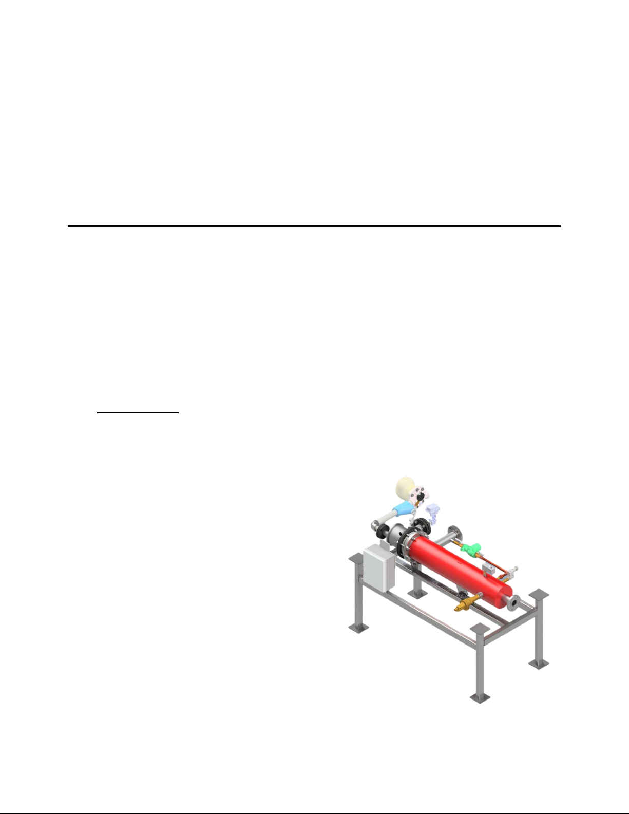
2.3 Major Components of the HX2
A general listing of the major, external components of an HX2, and their function, are as
follows:
2.3.1 The solenoid valve is an electrically actuated, normally closed valve that opens to
relieve tank pressure once a pre-set high temperature limit is exceeded. It should be
independently piped to a suitable gravity drain using a line size of the same size as
the solenoid valve discharge.
2.3.2 The resistance temperature detector (RTD) is a temperature probe immersed in the
tank flow stream near the discharge nozzle. Under normal operation it is a self-
contained device not requiring routine maintenance.
2.3.3 The high-limit thermostat is a primary safety feature that upon reaching a pre-set
high temperature limit, interrupts power to the control valve, causing it to close, and
energizes the solenoid valve to open.
2.3.4 The pressure/temperature (P/T) relief valve is a secondary mechanical safety device
used to protect against over-pressure or over-temperature conditions within the unit
tank. It should be independently piped to a suitable gravity drain using a line size of
the same size as the relief valve discharge.
2.3.5 The circulator pump consists of a pump/motor assembly with companion flanges. It
provides continuous circulation throughout the tank, which ensures a uniform
temperature distribution across all temperature sensors.


 Operation and maintenance instructions")