Recon BLOCKAGE+ User manual

INSTALLATION MANUAL
Document revision 1.0
Last revised: August 1, 2022

Recon Blockage Plus™Installation Manual
600840-000069, rev 1.0 Page 2 of 35
Recon Blockage Plus™
Installation Manual
© 2022 Intelligent Agricultural Solutions All Rights Reserved.
Recon Blockage Plus™Installation Manual. All content within is copyrighted by Intelligent
Agricultural Solutions and may not be reprinted without permission.
The content of this manual is furnished for informational use only, is subject to change without
notice, and should not be construed as a commitment by Intelligent Agricultural Solutions.
Intelligent Agricultural Solutions assumes no responsibility or liability for any errors or
inaccuracies that may appear in the content contained in this guide.
Recon and Recon Blockage Plus are trademarks or registered trademarks of Intelligent
Agricultural Solutions. Intelligent Agricultural Solutions, IAS, and the IAS logo are trademarks or
registered trademarks of Intelligent Agricultural Solutions. iPad and iPod are registered
trademarks of Apple Inc., registered in the U.S. and other countries. App Store is a service mark
of Apple Inc. All other trademarks are property of their respective owner.
Intelligent Agricultural Solutions, 1810 NDSU Research Circle North, Fargo, ND 58102 USA.
Visit us online at intelligentag.com
Questions? E-mail us at info@intelligentag.com

Recon Blockage Plus™Installation Manual
600840-000069, rev 1.0 Page 3 of 35
Table of Contents
Related Documentation............................................................................................................5
1. Introduction........................................................................................................................6
About Recon Blockage Plus™............................................................................................6
Required Tools and Equipment...........................................................................................6
Installation Overview...........................................................................................................6
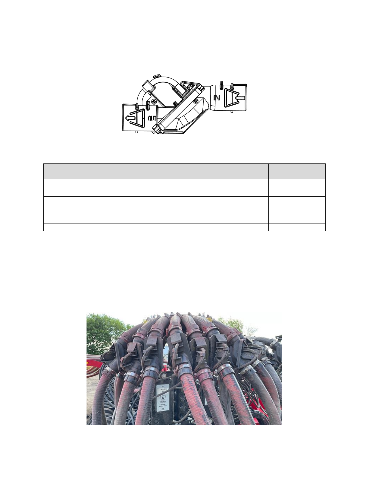
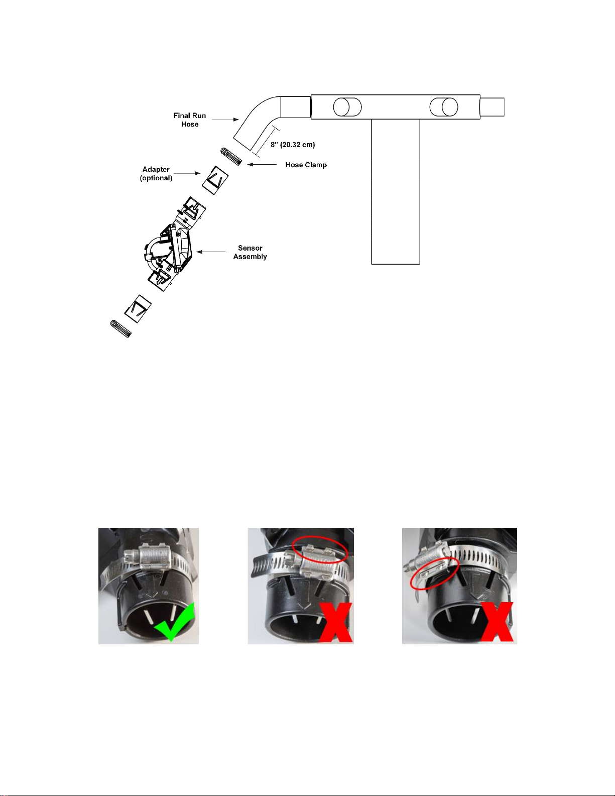
2. Installing Flow Sensors.....................................................................................................7
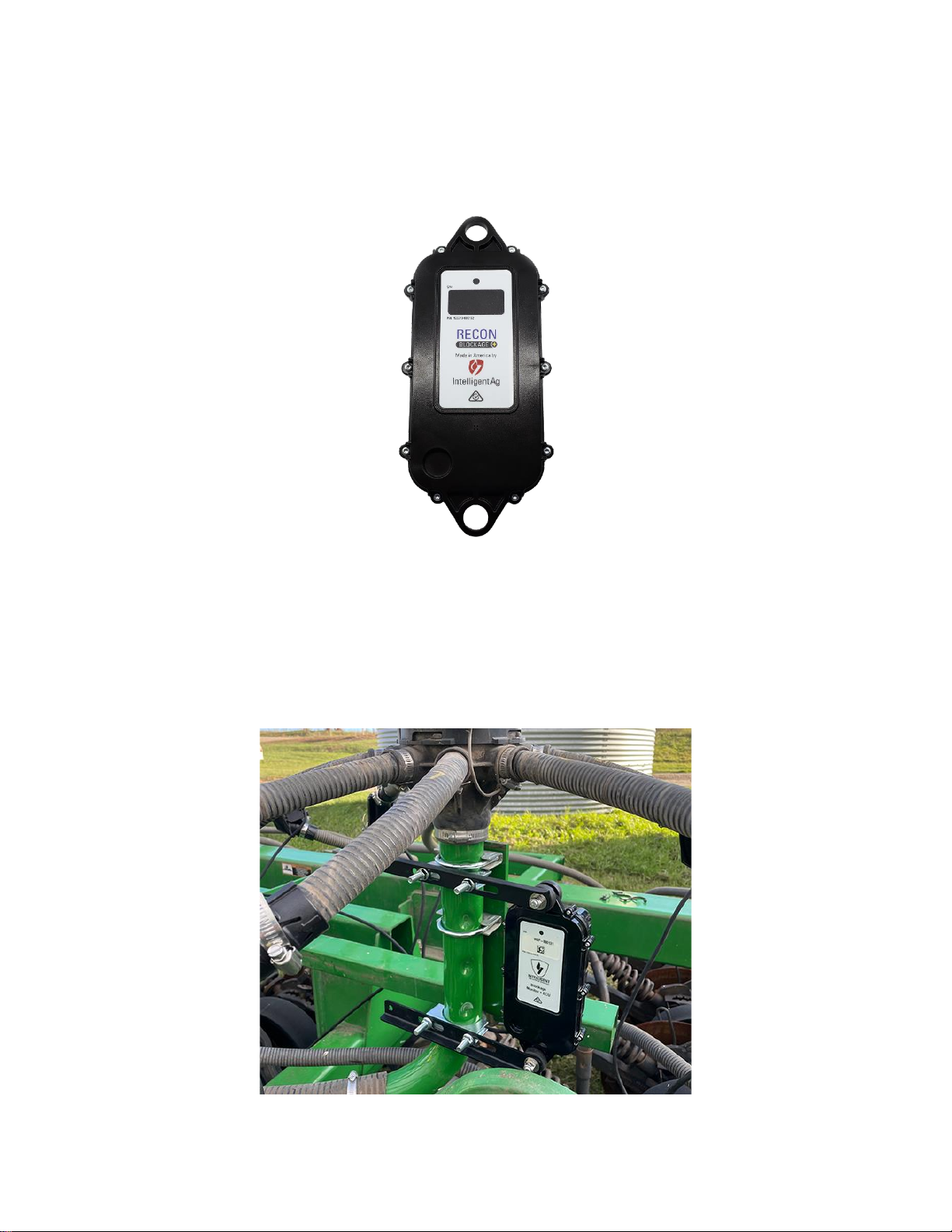
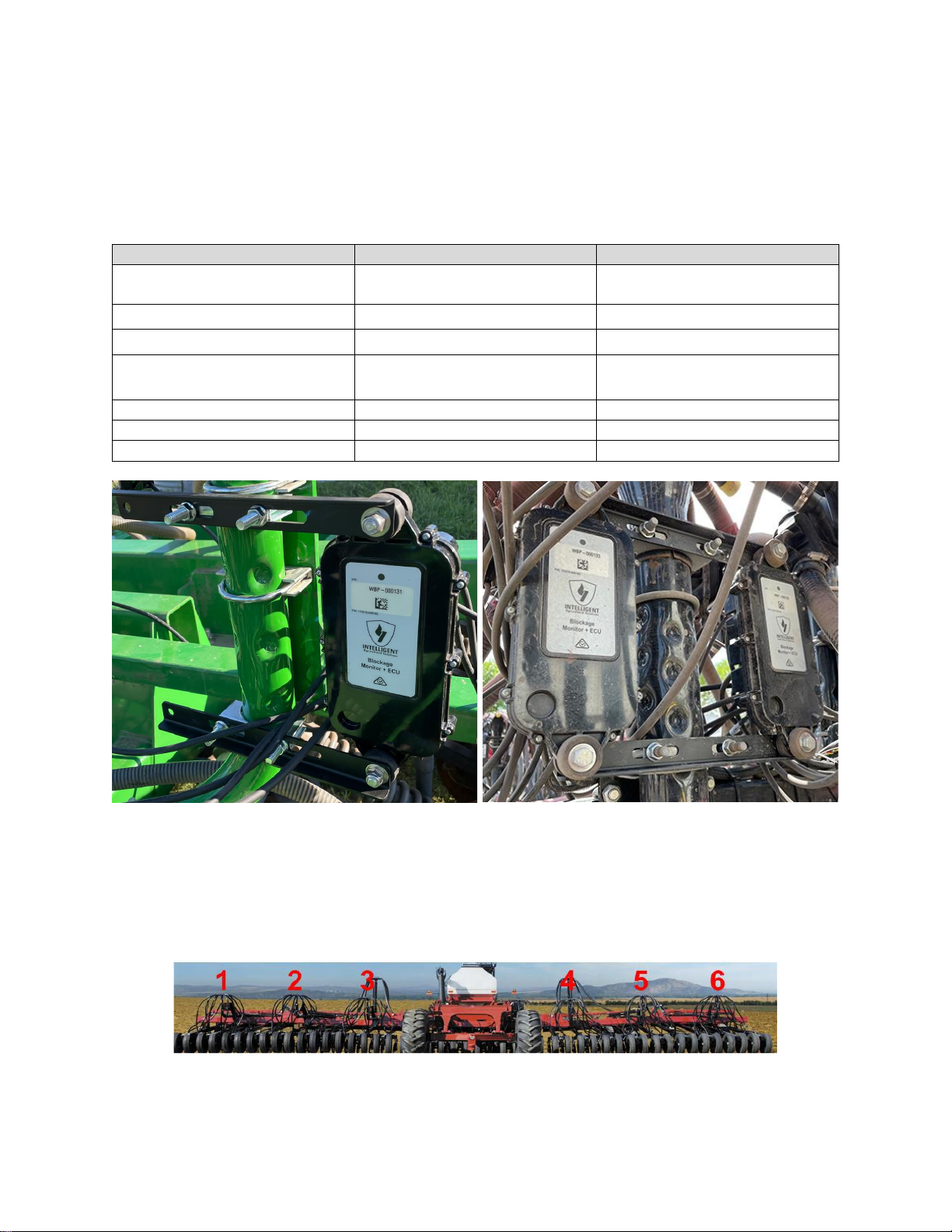
3. Installing ECUs ..................................................................................................................9
4. Connecting Auditory Tubes to ECUs .............................................................................15
5. Installing the Work Switch ..............................................................................................17
Installing the Work Switch.................................................................................................18
Verifying Work Switch Installation.....................................................................................18
6. Installing the Gateway.....................................................................................................19
7. Installing the Wi-Fi Antenna............................................................................................21
8. Installing Harnessing.......................................................................................................23
Installing 10’ ECU Harnesses (353050-000099) (dual-shoot only)..................................23
Installing 20’ ECU Harnesses (353050-000097) ..............................................................23
Installing the Gateway Harness (353050-000101)...........................................................24
Installing the Gateway Extension Harnesses (353050-000103) (Tow-Between Only)....24
Installing the Power Harness (353050-000098) ...............................................................24
Installing the Tractor Harness (353050-000100)..............................................................24
Securing Loose Harnessing..............................................................................................25
9. Installing the iPad Mount and App .................................................................................26
Installing the iPad Mount...................................................................................................26
Downloading the Recon Blockage Plus app.....................................................................27
Connecting to the Gateway...............................................................................................28
Appendix A: Wiring Harness Diagrams.................................................................................29
Appendix B: System Configuration Table.............................................................................35

Recon Blockage Plus™Installation Manual
600840-000069, rev 1.0 Page 4 of 35
List of Figures
Figure 1: Flow sensor..................................................................................................................7
Figure 2: Flow sensor installation location...................................................................................7
Figure 3: Installing flow sensors on a manifold............................................................................8
Figure 4: Correctly placing the hose clamps................................................................................8
Figure 5: ECU.............................................................................................................................9
Figure 6: ECU installation location ..............................................................................................9
Figure 7: ECU installed on a tower (standard installation).........................................................10
Figure 8: Installing the ECUs from left to right...........................................................................10
Figure 9: Securing ECU to brackets..........................................................................................11
Figure 10: ECU installed on a tower (horizontal installation)......................................................12
Figure 11: Installing the ECUs from left to right.........................................................................12
Figure 12: Securing ECU to brackets........................................................................................13
Figure 13: Auditory tube............................................................................................................15
Figure 14: Order to connect flow sensors to ECU .....................................................................16
Figure 15: Work switch..............................................................................................................17
Figure 16: Work switch mounting location.................................................................................17
Figure 17: Work switch functionality..........................................................................................18
Figure 18: Mounting a gateway.................................................................................................19
Figure 19: Example gateway mounting locations ......................................................................20
Figure 20: Mounting the Wi-Fi antenna.....................................................................................21
Figure 21: Example Wi-Fi antenna mounting locations..............................................................22
Figure 22: Gateway connections...............................................................................................22
Figure 23: Installing the iPad mount..........................................................................................26
Figure 24: Recon Blockage Plus app........................................................................................27

Recon Blockage Plus™Installation Manual
600840-000069, rev 1.0 Page 5 of 35
Related Documentation
Document Number
Document Title
600820-000044
Recon Blockage Plus™Quick Reference Guide
600820-000045
Recon Blockage Plus™Troubleshooting Guide
600890-000075
Recon Blockage Plus™Operator’s Guide

Introduction Recon Blockage Plus™Installation Manual
600840-000069, rev 1.0 Page 6 of 35
1. Introduction
About Recon Blockage Plus™
Intelligent Ag’s Recon Blockage Plus is an acoustic-based monitoring system that quickly and
accurately notifies operators of blockages anywhere in their implement. Operators interact with
the system via an iPad® app in the tractor cab.
For instructions to use the system after installation, see the Recon Blockage Plus Operator’s
Guide from the app’s Guides screen.
For current documentation, iPad and software requirements, and other resources, visit
intelligentag.com/support.
Required Tools and Equipment
You will need the following tools and equipment to install Recon Blockage Plus:
•Standard wrench and socket sets
•Measuring tape
•Cutting tool, such as a PEX tubing cutter, box cutter, or shears
•Pliers
•Phillips screwdriver
•Cordless drill and/or flathead screwdriver (optional)
•Paint pen or other permanent marking tool (optional)
Installation Overview
ESTIMATED INSTALL TIME: 6 hours
□Install flow sensors
□Install ECUs
□Connect auditory tubes to ECUs
□Install work switch
□Install gateway
□Install Wi-Fi antenna
□Install harnessing
□Install iPad mount and download app

Installing Flow Sensors Recon Blockage Plus™Installation Manual
600840-000069, rev 1.0 Page 7 of 35
2. Installing Flow Sensors
Flow sensors detect when product is flowing through the run.
Figure 1: Flow sensor
Provided Parts
Part Name
Part Number
Quantity
1-inch flow sensor or
1.25-inch flow sensor
153510-000022 or
153510-000066
1/run
Adapter (optional)
353070-000022 or
353070-000112 or
353070-000252
2/run
Hose clamp
356060-000025
2/run
Tools Needed
•5/16 inch socket, 5/16 inch nut driver on a cordless drill, or a flathead screwdriver
•Measuring tape
•Cutting tool, such as a PEX tubing cutter, box cutter, or shears
Installation Location
Installed at the beginning of every final run hose.
Figure 2: Flow sensor installation location

Installing Flow Sensors Recon Blockage Plus™Installation Manual
600840-000069, rev 1.0 Page 8 of 35
Installing Flow Sensors
Figure 3: Installing flow sensors on a manifold
1. If you are using adapters, snap them into the sensor in the orientation shown in Figure 3.
2. Cut each original run hose to about 8 inches (20.32 cm), or other length that allows for a
downward flow and appropriate fit once the sensor and adapters (if applicable) are
installed.
3. Orient the sensor (153510-000022 or 153510-000066) so that the flow arrows point
away from the manifold. Slide a sensor assembly on each final run hose piece until the
hose piece hits the backstop inside of the sensor assembly. Make sure that you install
the sensor so that the auditory tube is pointing up.
4. Secure using a hose clamp (356060-000025) between the two ridges on the end of the
sensor assembly, ensuring that the hose clamp lays flat and the head (worm drive) does
not hit the sensor ridge, as shown in Figure 4.
Figure 4: Correctly placing the hose clamps
5. Slide the remaining final hose piece into the lower end of the sensor assembly until the
hose piece hits the backstop inside of the sensor assembly. Secure using a hose clamp
between the two ridges on the end of the sensor assembly, ensuring that the hose clamp
lays flat and the head (worm drive) does not hit the sensor ridge.

Installing ECUs Recon Blockage Plus™Installation Manual
600840-000069, rev 1.0 Page 9 of 35
3. Installing ECUs
Electronic Control Units (ECUs) communicate the flow measurement data recorded by the flow
sensors to the gateway.
Figure 5: ECU
Tools Needed
•Standard socket set
Installation Location
Installed underneath each implement manifold.
Figure 6: ECU installation location

Installing ECUs Recon Blockage Plus™Installation Manual
600840-000069, rev 1.0 Page 10 of 35
Installing the ECUs (Standard Orientation)
NOTE: This section is for installing the ECUs in the standard (vertical) orientation. If your dealer
ordered you a horizontal mounting kit, skip this section and use the instructions in Installing the
ECUs (horizontal installation).
Provided Parts
Part Name
Part Number
Quantity
ECU
153510-000182
1/manifold
(for standard setup)
3/8'' lock nut
352011-000045
2/ECU
3/8'' flat washer
352012-000031
4/ECU
2.5” diameter U-bolt or
5” diameter U-bolt
352013-000007 or
356060-000108
2/manifold
Vibration damping mount
353070-000239
2/ECU
ECU mounting bracket
353070-000490
2/manifold
3/8" x 2" bolt
356060-000371
2/ECU
1 ECU per manifold
2 ECUs per manifold
Figure 7: ECU installed on a tower (standard installation)
NOTE: ECUs can be mounted in any order; however, we recommend installing the ECUs in
numeric order from left to right (when facing the back of the tractor) based on the ECU’s serial
number. The serial number is located on the front of the ECU. Use the table in Appendix B to
record your system setup.
Figure 8: Installing the ECUs from left to right

Installing ECUs Recon Blockage Plus™Installation Manual
600840-000069, rev 1.0 Page 11 of 35
1. Determine the number of ECUs (153510-000182) you need per manifold. The number of
ECUs you use depends on the number of runs per manifold.
Runs per Manifold
ECUs
7 or fewer
1 ECU for 2 manifolds
8-14
1 ECU per manifold
More than 14
2 ECUs per manifold
2. Secure the top and bottom of the ECU to a bracket using a 3/8" x 2" bolt (356060-
000371), washers (352012-000031), vibration damping mount (353070-000239), and
lock nut (352011-000045) as shown in Figure 9. Hand tighten.
Figure 9: Securing ECU to brackets
3. If you’re using 2 ECUs per manifold, install another ECU onto the other end of the
brackets.
4. Orient the ECU so that the LED faces the tractor (recommended). Use u-bolts (352013-
000007 or 356060-000108) to secure the center of the brackets to the manifold post,
right below the manifold. Hand tighten.
5. Adjust the assembly as needed and fully tighten the hardware.

Installing ECUs Recon Blockage Plus™Installation Manual
600840-000069, rev 1.0 Page 12 of 35
Installing the ECUs (Horizontal Installation)
NOTE: This section is for installing the ECUs in the horizontal orientation. If you’ve already
installed your ECUs in the standard (vertical) installation, skip this section.
Provided Parts
Part Name
Part Number
Quantity
ECU
153510-000182
1/manifold
(for standard setup)
3/8'' lock nut
352011-000045
2/ECU, plus 2
3/8'' flat washer
352012-000031
4/ECU, plus 4
2.5” diameter U-bolt or
5” diameter U-bolt
352013-000007 or
356060-000108
1/manifold
Vibration damping mount
353070-000239
2/ECU
ECU mounting bracket
353070-000490
2/ECU, plus 1
3/8" x 1" bolt
356060-000400
2/manifold
3/8" x 2" bolt
356060-000371
2/ECU
Figure 10: ECU installed on a tower (horizontal installation)
NOTE: ECUs can be mounted in any order; however, we recommend installing the ECUs in
numeric order from left to right (when facing the back of the tractor) based on the ECU’s serial
number. The serial number is located on the front of the ECU. Use the table in Appendix B to
record your system setup.
Figure 11: Installing the ECUs from left to right

Installing ECUs Recon Blockage Plus™Installation Manual
600840-000069, rev 1.0 Page 13 of 35
1. Determine the number of ECUs (153510-000182) you need per manifold. The number of
ECUs you use depends on the number of runs per manifold.
Runs per Manifold
ECUs
7 or fewer
1 ECU for 2 manifolds
8-14
1 ECU per manifold
More than 14
2 ECUs per manifold
2. Secure the top and bottom of the ECU to a bracket using a 3/8" x 2" bolt (356060-
000371), washers (352012-000031), vibration damping mount (353070-000239), and
lock nut (352011-000045) as shown in Figure 12.
Figure 12: Securing ECU to brackets
3. If you’re using 2 ECUs per manifold, install another ECU onto the other end of the
brackets.
4. Use 3/8” x 1” bolts (356060-000400), washers (352012-000031), and locknuts (352011-
000045) to install a third bracket across the center of the two brackets, as shown in
Figure 10.

Installing ECUs Recon Blockage Plus™Installation Manual
600840-000069, rev 1.0 Page 14 of 35
5. Orient the ECU so that the LED faces the tractor (recommended). Use a u-bolt (352013-
000007 or 356060-000108) to secure the center bracket to the manifold post. Hand
tighten.
6. Adjust the assembly as needed and fully tighten the hardware.

Connecting Auditory Tubes to ECUs Recon Blockage Plus™Installation Manual
600840-000069, rev 1.0 Page 15 of 35
4. Connecting Auditory Tubes to ECUs
The auditory tubes on the sensors allow sound to be transmitted from the sensor to the ECU.
Figure 13: Auditory tube
Tools Needed
•Pliers
•Paint pen or other permanent marking tool (optional)
Connecting Auditory Tubes to ECUs
IMPORTANT: Do not cut or change the length of the auditory tubes. This will cause incorrect
readings.
1. Remove the caps from the ECU ports that you will be using, beginning with ECU port 1.
You will use one ECU port per sensor on the manifold. The number of ECUs you use
depends on the number of runs per manifold.
Runs per Manifold
ECUs
7 or fewer
1 ECU for 2 manifolds
8-14
1 ECU per manifold
More than 14
2 ECUs per manifold

Connecting Auditory Tubes to ECUs Recon Blockage Plus™Installation Manual
600840-000069, rev 1.0 Page 16 of 35
2. Locate the auditory tube of the sensor that is closest to the tractor when facing the back
of the tractor (labeled “1” in Figure 14) and route it toward the ECU. connect the auditory
tube to the port labeled “1”. Make sure that the hose is not kinked.
Figure 14: Order to connect flow sensors to ECU
Default order on left (clockwise), Reverse order on right (counterclockwise)
3. Optional: Mark the flow sensor hose with the ECU port number that the sensor is
connected to.
4. Continue connecting auditory tubes to the ECU, working clockwise around the manifold
as shown in Figure 14.
NOTE: If you connect ports in the reverse order, you can change the run direction while
configuring the system in the app.

Installing the Work Switch Recon Blockage Plus™Installation Manual
600840-000069, rev 1.0 Page 17 of 35
5. Installing the Work Switch
The work switch signals to the app when the implement is in or out of the ground.
Figure 15: Work switch
Provided Parts
Part Name
Part Number
Quantity
Work switch assembly
353070-000534
1
Tools Needed
•None
Installation Location
Installed in a location where the work switch tilts from one end to the other when the toolbar is
changing from raised to lowered positions.
Figure 16: Work switch mounting location

Installing the Work Switch Recon Blockage Plus™Installation Manual
600840-000069, rev 1.0 Page 18 of 35
Installing the Work Switch
The work switch is a mercury switch, meaning the switch is engaged when the mercury inside is
tilted toward the wires and it contacts the electrical leads.
Mount the work switch (353070-000534) in a location where the work switch tilts from one end
to the other when the toolbar is changing from raised to lowered positions.
Figure 17: Work switch functionality
Determining Work Switch Method
The work switch uses one of two methods to determine when the implement is in the ground:
•Default method
oThe work switch is tilted toward the wires when the implement is in the ground.
oThe work switch is tilted away from the wires when the implement is out of the
ground.
•Inverted method
oThe work switch is tilted away from the wires when the implement is in the
ground.
oThe work switch is tilted toward the wires when the implement is out of the
ground.
Take note of your work switch method. It will be configured during system configuration in the
app. See the Recon Blockage Plus™Operator’s Guide (Intelligent Ag document number
600890-000075) for instructions.
Verifying Work Switch Installation
Refer to Section 2.3 of the Operator’s Guide for instructions to verify that the work switch was
correctly installed and configured.

Installing the Gateway Recon Blockage Plus™Installation Manual
600840-000069, rev 1.0 Page 19 of 35
6. Installing the Gateway
The gateway is a computing platform that sends ECU data to the iPad through the Wi-Fi
antenna.
Provided Parts
Part Name
Part Number
Quantity
Gateway 260
153010-000085
1
1/4” flat washer
352012-000002
8
U-bolt
352013-000007,
356060-000152, or
356060-000403
2
Gateway mounting bracket
353070-000079
1
3/8" locknut
(for square u-bolts)
356060-000094
4
3/8" washer
(for square u-bolts)
356060-000239
4
1/4" nut
356060-000241
4
1/4” x 2-1/2” screw
356060-000303
4
Tools Needed
•Standard wrench set
Installation Location
Mounted on the tractor or on top of the air cart. Refer to the steps below for specific mounting
locations for your air cart configuration.
Figure 18: Mounting a gateway

Installing the Gateway Recon Blockage Plus™Installation Manual
600840-000069, rev 1.0 Page 20 of 35
1. Position the gateway (153010-000085) on the mounting bracket (353070-000079). The
gateway can be mounted on the bracket in any direction, but the connectors should not
face up when the bracket is mounted on the air cart or tractor.
2. Secure the gateway to the mounting bracket using the provided screws (356060-
000303), washers (352012-000002), and nuts (356060-000241) as shown in Figure 18.
3. Mount the gateway according to the instructions below for your air cart configuration.
The mounting location must be at least 8 inches (20 cm) away from the operator to
ensure safe operation.
•Tow-behind: Mount the gateway on the exterior frame of the tractor or inside the
cab. Make sure that the gateway is within reach of the antenna cables. Secure it to
the mounting location using u-bolts and the included u-bolt hardware or locknuts
(356060-000094) and washers (356060-000239).
•Tow-between: Mount the gateway on the rear of the air cart catwalk, facing
rearward. Make sure that the gateway is within reach of the antenna cables. Secure
it to the mounting location using u-bolts and the included u-bolt hardware or locknuts
(356060-000094) and washers (356060-000239).
Example tow-behind mounting location
Example tow-between mounting location
Figure 19: Example gateway mounting locations
Table of contents
Popular Measuring Instrument manuals by other brands

ITRON
ITRON EM512 TYPE 700 JV1 Technical and user guide

TA Instruments
TA Instruments Q1000 manual

Emerson
Emerson MRLDS-250 Installation and operation guide

Eco-Eye
Eco-Eye Smart 3pA Series Set up and operating instructions

Polaris
Polaris Karat Flash Meter instruction manual

Trilithic
Trilithic Model One Operation manual