Recordio R-592 User manual

€
ff=
el -r
-l l-
e, lrl
Lq
RECORDIO
MODET R.592
9
o
4
o
I
ut
e,
-t
ll|
o
o
E
PnoTo FAcr' FolJ"t
,,i,#,
F
tn
6
o
7
I
o
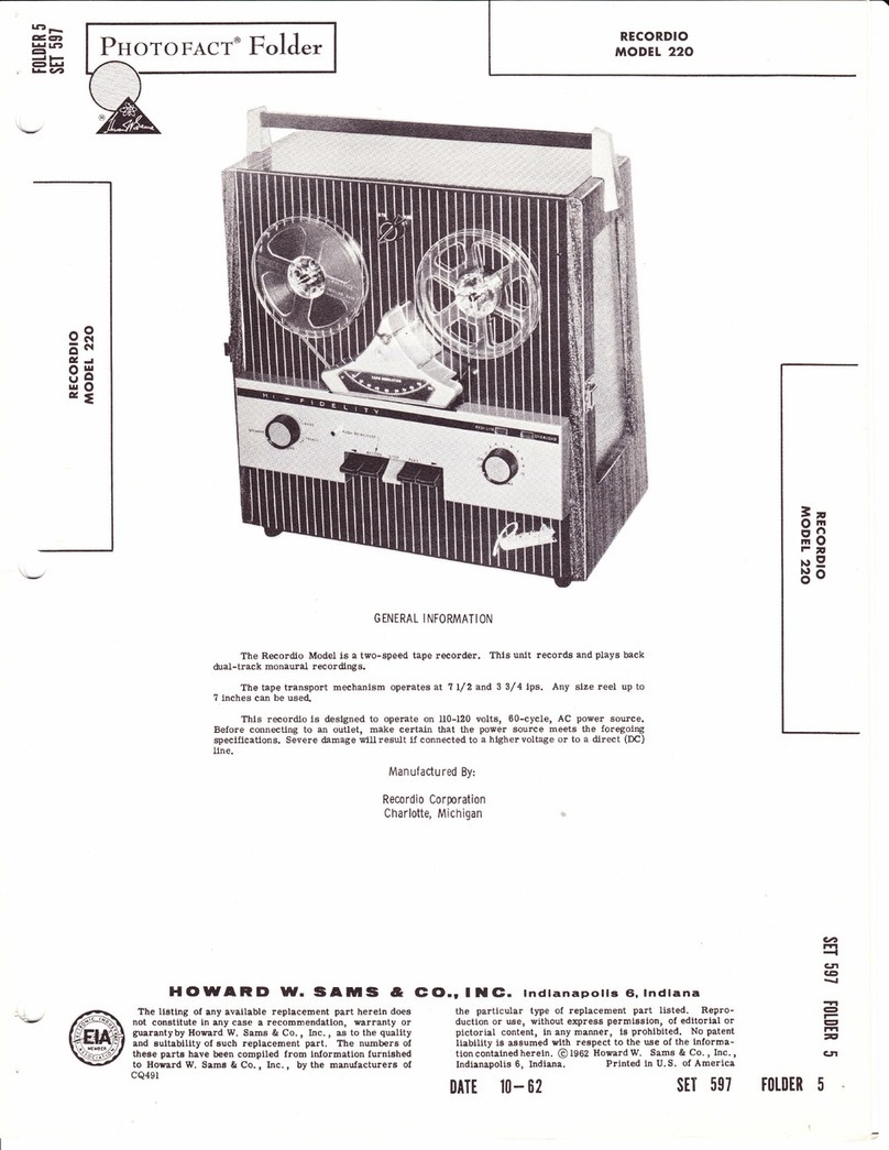
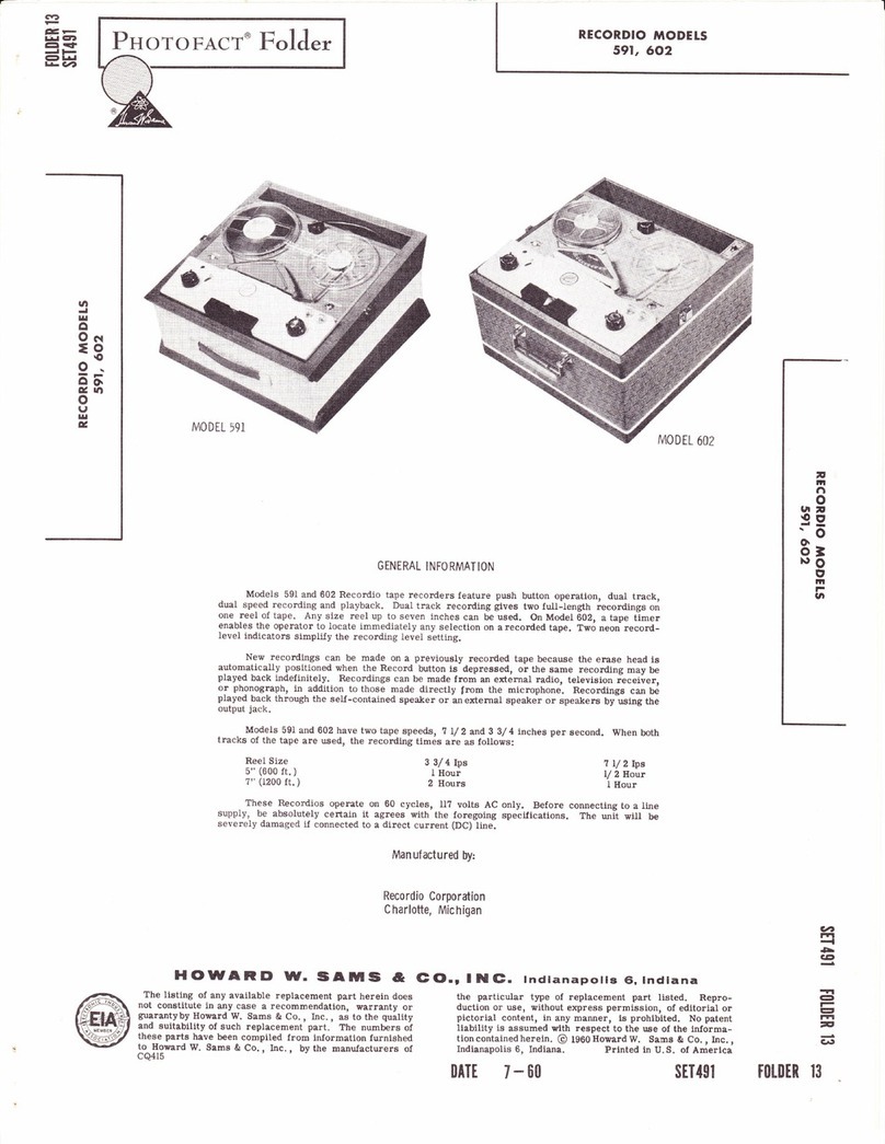
GENERAL INFORMATION
Model 592 Recordio tape recorders feature dual-track, dual-speed, monaural recording
and stereophonic playback. Double-track recording gives two full-Iength recordings on a reel
of tape. Any size reel up to seven inches can be used. A tape timer enables the operator to
Iocate immediately anyselection onarecorded tape. Two neon record-Ievel indicators simplily
the recording-level setting.
New recordings can be made on a previously recorded tape because the erase head is
automatically positioned when the Record button is depressed, or the same recording may be
played back indefinitely, Recordings can be made from an external radio, television receiver,
phonograph, or telephone, in addition to those made directly from the microphone. Recordings
can be played back through the self-contained speaker or an external speaker or speakers by
using the output jacks.
Model 592 has two tape speeds, 7 L/ 2 and 3 3,/ 4 inches per second. When both
the tape are used, the recording times are as follows:
Indianapolis 6, Indiana.
DATI 4- 60
tracks of
7 L/2lps
/ 2 Hour
I Hour
Printed in U.S. of America
stT 48t
Reel Size
5" (600 ft. )
7" (1200 ft. )
HOWARD W. SATUIS &
The liating of any available replacement part herein does
not constitute in any case a recommendation, warrantl or
guarantyby Howard W. Sams & Co., Inc., as to the quality
and suitability of such replacement part. The numbers of
these parts have been compiled from information furnished
to Howard W. Sams & Co. , Inc. , by the manufacturers of
CQ4I6
3 3/4 Ips
I Hour
2 Hours
The Recordio operates on60 cycles, ll7 volts AC only. Before connectingto a linesupply,
be absolutely certain it agrees with the foregoing specifications. The unit will be severely
damaged if connected to a direct current (DC) line.
Man uf act u red by:
Recordio Corporation
Charlotte, Michigan
G |o.r I t (C. lndianapolis €i, lndiana
the particular type of replacement part listed. Repro-
duction or use, \r'ithout express permission, of editorial or
pictorial content, in any manner, is prohibited. No patent
liability is assumed with respect to the use of the informa-
tion contained herein. @ tgOO Howard W. Sams & Co. , Inc. ,
v7
l-t
-l
5
CE
-l
e
E
l';l
-
GI
romEn 10

F IG. I TO P V IEW OF MECHAN I SM W ITH ESCUTCHION REMOVED
OPERATING INSTRUCT IONS
Preparing For 0peration
I. Remove the AC cord, reel of tape, empty reel,
and the microphone from the case storage
compartment.
2. Depress the Stop button.
3. Insert theAC cord into aeonvenient wall recep-
tacle of the proper rating and into the AC input
on the cabinet.
4. Set the Speed Change knob to 3.'i5 or ?. 50, as
desired.
CAUT lON: Do not turn Speed Change knob
unless Stop button is depressed.
When the Forward or Rewind buttons are de-
pressed, the Record and Play buttons are locked so
that they cannot be pressed down, with the possibility
of spilling the tape. The buttons should always be
pressed down firmly until they latch. Always depress
the Stop button before changing functions or speeds.
IMPORTANT: Always depress the Stop
button when the recorder is not in use.
Page 2
Threading The Tape
I, Place a reel of tape on reel pan (i5), making
certain the reel slots engage the protrusions on
the pan. Place an empty reel on reel pan (8),
again making certain the reel slots engage the
protrusions on the pan.
2. Unwind about 14 inches of tape from the suppiy
reel. Holding a section of tape straight with
both hands, insert it into the tape slot, making
certain the dull-coated side faces the heads
(rear of the unit).
3. Insert the free end of the tape into one of the
three slots inthe hub of the take-up reel. Whiie
holding the end in place, turn the reel two or
three times untilthe tape is secured tothe reel.
To Record From a Microphone
1. Turn the Right Channel On-Off-Yolume control
to the right, and allow about 30 seconds for the
unit to warm up"
2- Move the Record Lock lever downward with the
Ieft hand. This releases the Record Safety lock,

which prevents accidental erasure.
3. Depress the Record button with the right hand
(while holding the Record Lock lever with the
Ieft hand) until it latches.
4. Adjust the large, outside knob (Iocated on the
left) until the normal level indicator justflashes
while you are speaking into the microphone.
The Overload indicator may flash occasionally
on peak passages. It should not flash continually,
which indicates distortion.
5. The Tone control is automatically disconnected
when the unit is recording. When recording
from a radlo, set the radio tone control for
maximum treble.
NOTE: To Monitor the recording, place
the Monitor switch in the On position. Al-
ways turnthe right-channel Volume control
to minimum before recording.
To Record From an External Rdio, TV Receiver,
or Phonograph
I. Insert adaptor plug A-601 into the Microphone
jack.
2. Insert the phonographplug into the adaptorplug.
3. For radio or TV recording, connect the patch
cord(Part No. C20.233) tothe voice-coil term-
inals of the radio or TV receiver spealer by
means of the alligator clips. Plug into the
Microphone jack.
4. Proceed with recording as described under
"To Record From Microphone".
N0TE: Remove patch cord and accessory
plug after recording.
To Use Second Track
I. Depress the Stop button after all tape has been
wound onto the take-up reel.
2. Remove reel containing tape, and place on left
(supply) reel.
3. Place empty reel on right (take-up) pan.
4. Thread the tape, and proceed with the recording
as previously described.
To Erase Tape
When the Record button is depressed, the erase
head is automatically positioned, erasing any previous
recording while anew one is being made. Material no
Ionger needed can be erased, vithout recording, by
depressing theRecord button and turning the left Vol-
ume control knob to its minimum position. One track
is erased at a time. To erase the second track, re-
verse the reels and repeat the foregoing operation.
To Play Recordings
l. Thread tape as described under "Threading the
Tape".
2. Set the Speed Change knob to the speed at which
the recording was made.
3. Depress the Play button until it latches.
4. Adjust thevolume and toneto thedesired listen-
ing level.
NOTE: The speaker Monitor switch must
be in the On position.
High-Speed Forward or Rewind
To play acertain portion of the tape over again,
it is not necessary to rewind the entire reel. De-
pressing the Forward or Rewind buttons will rapidly
advance or reverse the tape.
Several minutes of normal recording can be
skipped in a few seconds by using the Forward and
Rewind buttons.
Tape Timer
If you wish to play back a certain recording while
making a recording or playing back a tape, note the
reading on the Timer scale at the time the particular
reading is being made or heard. Rewind the tape un-
til tlte same number appears on the scale. Depress
the Stop button, and then the PJ.ay button.
When starting anew reel or rerecording a reel,
reset theindicator pointerto"O"by rotating tfie Reset
knob. By starting at "O" on all tapes, you can catalog
the number location for each selection on any reel.
To Use Extension Speaker or Speakers
For bette r tone quality and power than the inte rn -
al speakers can provide, it is suggested that large
external speakers be plugged into the External Speaker
jacks.
The Recordio Model DS-599 dual-extension
spealer set enables you to use two speakers, giving
more power and sound. Each speaker has a speaker
jack, sothat onespeaker canbe plugged intothe other.
Thus, both speakers are in operation for better mon-
aural soundon straight playback or when the recorder
is used for public-address systems. However, the re-
corderis suitable for use with anyextension speakers
of the permanent-magnet type, provided they are
matched and have a 3- to 8-ohm voiee coil.
For stereophonic playback, plug each extension
speaker into its corresponding jack; plug the left ex-
tension speakerinto the external speaker jackmarked
Left, and the right extension speaker into the extension
jack marked Right. Place the two extension speakers
(or the recorder and one extension speaker) about ten
feet apart. Turn the speakers until they are at a 45-
degree angle to each of the side walls, with the fronts
of the speakers toward the walls and not the center of
the room.
To Play Stereophonic Tapes
l. Thread tape in normal way.
2. Turn right knob to the On position.
3. Depress the PIay button; and turn the large,
3
9H
sf|
FO
7t
?og
go
t\t
Tl
o
(:,
rfl
n
o
Page 3

t
A
IO
-
outside, left knob to the desired audio level-
this is the left channel of the tape only.
4. Turn the right knob (right channel) to the point
where the volume is the same as that of the left
channel.
5. Adjust the Tone.(small inside knob, Ieft side)
forthe most desirable listening of the highs and
Iows.
To Play Stereophonic Records
When astereophonic playback turntable is used,
FIG.2 BOTTOM VIEW OF MECHANlSM
D I SASSEMBLY INSTRUCTIONS
stereo records can be played directly through the
recorder, without additional preamps, amplifiers, or
speakers.
l. Insert the two turntable output cables into the
left and right input jacks.
2. With the recorder in t}le Stop position, turn the
right knob to the On position, and proceed as in
"To Play Stereophonic Tapes". The speaker
Monitor switch (on the right side) must be in
tlte On position.
To Remove Unit From Case
I. Remove Volume and Tone control knobs.
2. Remove two Phillips head screws from front
escutcheon.
Remove two hexhead screws from front of base
plate.
Remove two Phillips head screws from the rear
compartment.
Remove Phillips head screw holding AC cord to
cabinet.
6. Lift unit out of case, removing speaker leads
from speakers before removingunit completely.
7. To reassemble, reversetheforegoingprocedure.
To Remove Amplif ier From Transport Mechanism
1. Remove the motor and power-transformer plug
from the amplifier chassis.
2. Removethefourhead leads from the play-record
head terminal lugs.
3. Remove two slotted-head machine screws from
each end of ttre amplifier chassis.
3.
4.
5.
Page 4

F IG.3 BOTTOM V IEW OF MECHAN I SM W ITH D R IVE MOUNT ING PLATE REMOVED
4. Carefully lift the amplifier away from the trans-
port mechanism, and disconnectthe play-record
switch actuating link.
5. To reassemble, reverse the foregoing procedure.
ADJ U STMENTS
=
9H
E8
n
FO
lr
go
)9
Pressure-Pad Adjustment (Refer to Exploded View)
l. Remove front escutcheon (l ).
2. Depress the Play button. Do not turn the re-
corder on.
3. Using a pencil-type postal scale, check the
pressure needed to just puII the right pad away
from the play-record head. The test should be
made at the end of the pressure-pad mounttng
spring. If necessary, adjust locked adiustment
screw (50) untif a reading of t 3/4 ounce !l/ 4
ounce is obtained.
4. Adjust guide post pressure pad (left pad) by
bending pressure pad spring (49). It must be
adjustedfor minimum pressure against the tape.
N0TE: After making the adiustments, de-
press the Stop button, and replace the front
escutcheon.
Erase Head Adjustment
l. With tape properly threaded, turn recorder on,
and depress the Record button. Allow tape to
run for a few secondsl then turn recorder off,
but Ieave Record button depressed.
2. With timer escutcheon (7) and front escutcheon
(14) removed, check erase head (28) to see that
it is parallel with the tape.
3. Make sure the top edge of the tape coincides
with the top end of the diagonal slot in the erase
head(junction of long diagonal andshort vertical
slot). (See Fig. l. ) To adjust the level of the
tape, loosen set screw (24), and rotate tape
guide post (25) to move the tape up or down.
(See Exploded View. )
Brake Shoe Adjustment
I. With all push buttons in the up position, brake
O
I
n
O
Page 5

pads (81) should clear brake drums (123) and
(I33) by approximately I/ 8 inch.
2. Depress theStop buttonwhile observingthe brake
pads. Both brake pads must contact the brake
drums at thesametime andwith equal pressure.
3. If necessary, adjust the pressure by bending
brake spring (80).
Head Align ment
Use standard 6- or 12- alignment tape for this
procedure.
Remove front and rear escutcheons. Clean pole
pieces of play-record head, using a good commercial
head-cleaning agent, naptha, orlighter fluid. proceed
Most defects, other than wear or breakage, can
be traced to dirty surfaces. Stereo head (35), the
capstan, and pinch roller (43) may accumulate tape-
coating oxide, which is worn off the tape as it passes
these parts. This accumulation should beperiodically
FIG.4 DRIVE MOUNTING PLATE ASSEMBLY
CLEAN ING
LUBRICATION
l.
as follows:
l. Thread alignment tape on recorder, and turn
right-channel volume on full. Connect VTVM to
Right Channel External Speaker jack. Set meter
for AC volts, 3-volt range.
2. Place unitin Play position, 7 L/ 2 Lps. Decrease
volume until output is I volt on meter. Rotate
play-record head adjustment screw (33) until
maximum point of deflection is found.
3. Gently press the pressure pad at a point to the
extreme right of the play-record head. The
output should not increase. If it does, slightly
readjust the pressure pads. (See "pressure
Pad Adjustment").
removed because it will cause faint recording andpoor
playback. Wipe these surfaces carefully with a clean
cloth. If dirt is caked or hard and wiII not come off
with a dry cloth, dampen the cloth slightly with alco-
hol.
AII rotating parts have generous sized Oilite
bearings, which arefactory lubricated. Under normal
use, no further lubrication is necessary. In heavy-
duty service, the following parts should be Iubricated
once a year with a drop of No. 20 motor oil.
Page 6
The top and bottom motor bearings.
The capstan bearing.
2.
3. Pinch roller (43) bearing.

4.
5.
AII idler and drive-wheel bearings.
The reel-spindle bearings.
The basic rule is - do not
tothem. Always wipe excess Iubricantfrom Iubricated
parts.
Occasionally remove foreign matter fromunder
the plastic push-button cover, and place a drop of oil
on the sliding lever members.
must be kept off aII rubber idlers
wheel rim, and off any parts that
overlubricate. Oil
and belts, the fly-
might transfer oil
TROUBLE CHART
Symptom Cause Remedy
Motor and amplifier dead. I. Power-supplydefect.
2. Damaged power cord.
3. Defective On-Off Switch.
l. Checkvoltages perschematic.
2. Repair orreplace powercord.
3. Replace On-Off switch.
Does not record. I. Fautty microphone or cord.
2. Faulty input jack.
Faulty tube.
Open play-record head (35).
Replace if necessary, after
checking recorder with an-
other type of input.
Check input jack, and replace
if necessary.
Check tubes.
Check continuity. After check-
ing, demagnetize head.
3.
4.
2.
3.
4.
No erase, or erase is in-
complete. Erase head tension spring
(46) disconnected or broken.
Erase head (28) not adjusted
properly.
I. Connect or replace spring(46).
2. See "Erase Head Adjustment"'
under "Adjustment".
3
9*
E8
-
?e
so
}9
I.
2.
Flutter. l. Dirty stereohead(35), pres-
sure pads, capstan shaft, or
pinch roller (43).
l. Clean as described under
"Cleaning".
Wow. l. Brake return spring (?4) dis-
connected or broken.
OiI or foreign matter on
drive surlaces.
I. Connector replace spring(?a).
2. Clean witha cloth andalcohol.
2.
Tape spills when Stop button
is depressed duringfast for-
ward or rewind.
l. Brakeshoe outof adjustment.
2. Brake pads wornoutormiss-
ing.
See "Btake Shoe Adjustment"
under "Adjustment".
Replace brake pads.
t.
2.
No fast forward or rewind, Idler Iever tension spring
(?9) disconnected or broken,
thereby not actuating idlcr
(85).
Idler drive belt (I0l) broken
or not properly connected.
I. Connector replace spring(79).
2. Replace idler drive beft (l0l).
2.
Tape fails to wind ontq takeup
reel during Play or Record. ReeI drive spring (44) loose,
disconnected, or broken.
Reel pan shaJt (8) binding.
Connect or replace reel drive
spring (44).
Remove foreign matter from
bearing surfaces and shaJt
wlth clean cloth. Lubricate
with one drop of No. l0 motor
oil.
I. I.
2.
2.
I. Idler tension spring (128)
disconnected or broken. I. Connect or replace spring
(r28).
o
t-
g
n
o
No drive in Play or Record.
Page 7

i
#
-7iM
(, u-l
4\ l@
ffi
Ire
g ----@
Yt ---O
ffi
HHHffiff
wwwww%
*ffi
re
@--P
FIG.5A EXPLODED VIEW OF PARTS ABOVE BASEPLATE
Page 8
t-
I

@
6
A PHOTOFACT "EXPLODED" VIEW
@Howud W. Samr & Co., lnc. 1960
FIG.58 EXPLODED VIEW OF PARTS BELOW BASEPLATE
3
g5
?g
ln
so
}\'
TT
o
l-
I
rrt
n
Ft
o
Page 9

TROU BLE CHA RT (CON'T. )
Symptom Cause Remedy
2. Idler slide plate (106) binding
on idler slide bushing (10?),
thus preventing idler wheel
(135) from moving forward.
2. Check idler slide piate (106)
and bushing (10?) for burrs.
Clean with a1cohol.
Push buttons fail to latch into
position. l. Locking plate spring (58)
disconnected or broken. l. Connect or replace locking
plate spring (58).
Poor high - frequency re-
sponae. Head not making proper con-
tact with tape.
Improper head alignment.
Faulty amplilier.
I. Clean the head.
Align head.
Use standard audio trouble-
shooting procedures.
2.
3-
2.
3.
Hum Microphone near eguiPment
producing hum.
Microphone leads insuJfi-
cienily shielded.
l. Move microphone away from
equipment.
2. Make sure leads are ProPerIY
shielded.
2.
Tape scrapes against edge of
reel. I. Reel warped.
2. Tape guides out of adiust-
ment.
Replace reel.
Realign tape guides.
l.
2.
Distorted recordingl low
volume due to no recording
bias.
Faulty bias oscillator tube Vl
or oscillator coil Ll.
Faulty play-record head.
I. Check Vl or Ll and replace.
2. Replace head.
2.
MECHANICAL PARTS LIST
25
26
21
28
29
30
3l
32
33
34
35
36
3?
38
39
40
4I
42
43*
44
45
46
IO
u
L2
r3
I4
15
16
l?
r8
I9
20
2L
22
23
24
I
2
3
4
5
6
1
8
I
Part
No.
c-r3. 253-?
13-2254-3
51-4C-624-5
57-4C-405-5
B-32. 302-2
?3-2334-t
B-13.292-2
c-r3.318-0
B-28. 163
c-13.422-L
57-rC-618-r
B-35. 851-l
B-r9.9?5-2
B-13.295-8
c-13. 318-0
c-13.4r?-r
c-r3.416-I
57-4C-610-5
B-19.156I
B-33.446
E-13.423'I
57-3439-0
Speed Shift Knob (Black)
FeIt Washer 3/ axI/ 4 I. D. x
L/ L6
#6-32 x I /2Phillip'so.I{.M.s.
#4-40 x5/ t6 O" n. M. S. PhiI. St.
Timer Knob
#6 Cantlink Washer
Timer Escutcheon (Silver)
Nylon Reel Pan and Shaft AssY.
Linen Washer 3/ 8 x 7 / 32 x, 0L0
Black Varnished
Volume-On-Off Knob (glact)
. 250 Shaft W/. 156 Flat
#6-32 x I lrl I Philip's B. H. M. S
Timer Shaft and Indicator AssY.
Rear Escutcheon Plate
Front Escutcheon
Nylon Reel Pan and Shalt AssY.
Tone Control Knob (nfack)
Volume Control Knob (Black)
#6 -32 x 5/ 8 Phillip's o. Ir. M. S.
Screw
Spacer
IIex Nut
Spacer (2)
Base Plate, GraY Hammertex
#6-32 x 3/ 16 Bristol Head Set
Screw
B-32.300
48-4r0-r
B-32. 260
B-35.1048-l
B-ig. t4I0-I
c-35. 106?-3
5?-3439-0
B-32.282
5?-3I02-I
'13-223L-L
B-36. 250
8-36. 248
5?-rc-603-2
73-223r-4
B-28.163
B-33.404*
B-31.351
B-28.163
B-3I. 361
Tape Guidepost (Left)
#6-32 IIex Nut
Tape Guide Post Spacer
Erase Head Assembly
Erase Head Plate
Pinch Roller and Record Head
Assembly
#6-32 x 3/16 Bristol IId. Set
Screw
Tape Guide Post (Right)
#4-36 x V 4 R. H. M. s.
(Azimuth Adj. )
#4 Int. Lockwasher Sti. C. P.
Stereo llead W/M
Stereo Head Mr/ M (Alt. for
B-36.250)
Play-Record Head Bracket
; Assy.
Int. Tooth Lockwasher
#2-56 x 3/ 16 Hex Nut
#6-32 x 3/16 B. H. M. S. Stat.
Brz. (2)
#6 Int. Lockwasher (2)
riE* Illtlg 3/16 Shaft
Linen Washer
*Pinch Roller
ReeI Drive Spring BeIt
Linen Washer
Erase Head Tension SPring
Page l0

Ref .
No. Part
No. Description
47
48
49
50
5l
52
52.A
53
53A
54
55
56
5?
5?A
58
59
60
60A
6i
62
63
64
65
66
6?
68
69
70
?I
72
?3
74
?5
?6
77
?8
79
80
8i
82
83
84A
84
85
86
8?
88
89
90
9I
92
93
94
95
B-3r.334
5?-rc-603-2
B-35.1047-r
57-l6C-606-r
B-31.360
B-I9.88r
B-35. I045-1
B-35. 882-r
B-r9. 868
B-33.4r2
B-I3. 258-8
B*I9.859
B-3r.343
B-19. 8?0
B-33. 529-2
B-33. 528-2
B-19.8?6-r
48-2219-r
B-r9.858
5?-rc-603-2
13-2231-4
B-35. ?75-l
B-3r. 338
B-35. ?74-r
13-2241-154
57-3445-t
B-31. 338
48-2221
73-224r-148F
B-35. 1046-r
B-35. 835
B-3r. 339
B-35. 1070-r
B-28.163
73. 2248-39
B-35. l05r
B-31.382
B-32. 2?5
B-35. 859-2
57-34e9-0
B-3r. 333
B-33. lr8
13-2231-4
5?-rc-603-2
73-2231-4
Felt Pads (2 used)
#6-32 x 3/16 B. H. M. S. Sta.Brz
Pressure Pad Assembly
#6-32 x 3/ 8 R. H. M. S.
Pinch Roller Spring
Playback Actuating Lever
Playback Slide Plate Assy.
Record Actuating Lever Assy.
Record Slide Plate
Push-on Stud Nut for 3/16 Stud
Flat Washer
Push Button (Black)
Push-button Hinge Bracket
Push-button Return Spring (2)
Locking Plate Spring
Locking Plate for Push Button
Midget Jack Closed Circuit
3/ 8" Lg. Bushing (nxt. Speaker
2)
Midget Jack Open Circuit 3/ 8"
lg. Bushing ( Microphone)
Push-button Lever
#6-32 x 5/16 Keps Hex Nut
Push -button Retaining Bracket
*S-32 x 3/ 16 Phillips B. H. M.S.
#6 Int. Lockwasher
Phillips Head Screw
Washer
Washer
Interlock Lever and Handle
Assy.
Interlock Lever and IIandIe
Assy. Return Spring
Record Interlock Assy.
Lockwasher 5/16 O.D. x.I44
#8-32 x 3/ I R. H. M. S.
Brake Return Spring
#10-32 Hex Nut (Elastic Stop
Nut)
Flat Washer L/ 2 O. D. x . 205
I. D. x L/ 32 SU. C. P.
Shift Plate Assy.
Brake Slide Plate Assy.
Idler Lever Tension Spring
Brake Spring Assy.
Brake Pad FeIt
Phillips Head Screw
Hex Nut
Linen Washer
FIat Washer .425 O.D. x.255
x .0?0 Phenolic
Idler Lever Assy.
Spring Washer
#8-32 Hex Hd. ShoulderScrew
Switch Lever Assy.
#6-32 x 3/16 Bristol Head Set
Screw
Switch Arm Link
Phono Jack (2)
Spacer For Gear Train
#6 Int. Lockwasher
#6-32 x 3/tO B. H. M. S. Phillips
#6 Int. Lockwasher
MECHAN ICAL PARTS LIST (CON'T. }
* Walsco Replacement Part No.
1430 Idler Drive Belt, I45? Pinch RoIIer.
v
tn
t'!
o
F
I
o
TT
o
I
rr1
n
o
Ref .
No. Part
No. Description
o
Ill
F
-
96
9?
98
99
r00
101 *
r02
103
104
105
106
l0?
r08
109
il0
UI
Ltz
lr3
It4
115
u6
u7
u8
lr9
r20
12I
122
r23
124
125
r26
127
128
129
r30
l3l
i32
133
134
135
r36
13?
138
139
r40
r4i
142
143
t44
145
146
5?-rc-614-l
D-33.445
c-19. 837
B-28.163
B-35.1066
B-28. I8l *
B-28.163
B-32. 288
57-3589-r
B-35. 1064-1
B-32.264
B-r9. 143r-r
B-32. 29r-r
B-3r. 32?
B-35.1044
B-32. 275-r
B-28. 163
B-33.405
13-2254-6
B-33.40?-r
5?-lc-603-2
73-2231-4
B-r9.96r
B-35. 816-r
c-35. 835-r
5?-3589-l
B-r9.9?6-r
73-2231-5
57 -6C-805-l
B-31.324
5?-6C-805-r
B-28. i94
c-13.25?-l
5?-3589-l
c-35. 835-r
57-3589-l
B-33. 408
73-223r-5
57-6C-805-l
B-r9.862
57-6C-805-l
D-35.1054
B-33. 4u
48-2221
D-36. r53
D-36.24r
B-r9.887-l
c-r9.1553
B-19. 8?8-I
B-28. l8l
#6-32 x 1/ 8" B.H. M. S. Phillips
Gear Train for Tape Index
Motor Adaptor Plate
Linen Washer
Sheave Pulley Assy.
* Idler Drive Belt
Linen Washer
"E" Ring, 3/16" Shalt
Motor PuIIey
#8-32 x v4" Bristol Hd. set
Screw
Idler Slide Plate Assy.
Idler Slide Bushing
Flat Washer Steel
Idler Throw-out Lever
Shouldered Washer
Idler Lift Compression Spring
Sub-Idler Plate Assy.
#8-32 Hex Hd. Shoulder Screw
Linen Washer
Sub-Idler Wheel
FeIt Washer
"8" Ring 3/ 16" Shaft
"CttWasher
t6-32 x 5/16" Phillip's B. H. M. S
#6 Int. Lockwasher
Detent Spring
Speed Control Shaft Assy.
Brake Drum and Bushing Assy.
#8-32 x l/4 Bristol Hd. Set
Screw
Drive Mounting Plate Bracket
#8 Int. Lockwasher
#8-32 x 5/ 16" Phillip's R. H. M. S
Idler Tension Spring ( 2)
#6-32 x 5/ 16!' Phillip's B. H. M.S
Lord Shockmount (3)
Flywheel
#8-32 x I,/4" Bristol Hd. Set
Screw
Brake Drum and Bushing Assy.
#8-32 x V4" Bristol Hd. Set
Screw
Idler Wheel, 2 L/ 2,' Dia.
#8 Int. Lockwasher
#8-32 x 5/16" Phillip's R. H. M. S
Angle Bracket for Mounting
Drive Assembly
#8-32 x 5/16" PhiUip's R. H. M. S
Drive Mounting Plate Assy.
Flat Washer 3/ 4 O.D. x B/16
I. D. x . 050 (3)
#10-32 Hex Nut (Elastic Stop
Nut)
Motor Round Tlpe Fasco
Motor Universal
Fan Blade (Used With Fasco
Motor)
Fan Blade (Used With Universal
Motor)
Speed Shift Lever
Counter Belt
Page ll

AMP CHASS IS . BOTTOM V IEW
t {I ') 1
*;F - 4.-.J#P --
Page 12
AMP CHASS IS - BOTTOM V IEW

3
9H
E8
F
?E
rr
so
N'
-n
O
l-
I
rrt
n
H
o
c{
os
od
c
ad
EE
-
:
t
o
2
o:
E$
i 3x
&gE
\z s;
Ei uU
;i z:
F;;i
x3 sE
o
RH R H
@
d,
o
F
g
l+l
=
e
o
lrl
J
_J
co
v)
(v)
N,
F
><
In
@
=
c
-E<
co
R EE
i =@'
rots
N5
o
o
6{
@
E=s@
@
&.
l4J
v
lrl
o.
6v,
SE
Z-
e.
lrJ
F
x
IJz
o
u
z.
=
6
<o-
o>
d5
lrl
_o
1o-
s=
=<
E,J
23
-1ll z.
Eq
r.nE
-J
lrl
z
z
!
o
tr
:i
u._
ts<.r
E;
v
(J
&
l4I
!Z
ial
o-
tfl
J
2
E
l4l
F
x
U5@
A
\s/
-
!Z
o
ts
N
@
E
E
R
-lHt,'
@
LlrCo
-.-L!
-J-e,
6 G'l
@tE
c
o
ts
N
@
t\
@
F
)
o-
F
=
osz
p
o
ro
o
l\@
rft
+X
lD&:
o
o
(\
@
!z
R
AI
-\A "
/a
\g/
ctl
qt
E
o
*
9Jt',
Ee
o
E
E
o
o
6
o
st
v
F
qt
@
@
6
=
!o
o
e
o-
=
14-
<
C
E
obe
8=
R
z
=
o
-
a./l
=
Ec)
ag
q-6
dd
rO
oc)
3F
(J-
lr) 2
e.=
Be
o
E
E
o
@
@
I\
6-J
E$
"e
oo'5-1lr'
I .b,
@
)z
o
-l
@
Y
R
st
A
o (E/
>X
9lr, a
E
o
=
E !e.
:d
o
o
=l
:z
ril
@
@
€
=
o
I
e
E
F!€'
56
o
R
BS
o
E
E
o
E
@
ne
@
Q)sz
cLo
gR !Z
EEF a
e=
egJ
32
i >. tr.l
* d6
dqri-
uF=
=h(2
^u
v\z
*c)
C.)O
<. tt
";;
)a^. i6
'E o=
(oc.o :!,
E€.A ; E
c o 93 qrc
(r)xco
EL*:(J
E se Ex
o=]: o-
O<E'J
:E gEE
'a.pg36
E s;i h
H! E E g
FE FS;
iE o= =
eooOJ
a).!= > t:
k lo X c'E
aFEFE
- = O -.s
=EL-l!
€ o9* -
- c'rO O:
p Gr# -:J
9*r B€
=; c'E X
F o'E.E 6
EEE E=
"i =: ,ri _cj
v
F
UJ
I
w
vt
z3
ge
Fd
<l
l-
ei
z- d
6-
eE
<d
2;
(-p
F:
u!' o
FT
lo
l!
o
F
o
-
IL
r..)
;615:
-\-g/.=
€ <t:
-_
(D
(1)
E
=
o
.o
IE
lr
ld
I e.g
I ::? o)
I =E'5l(-,>_
i * suE
I --cs*
I EEE;
I obo-
I is *8 =
1 *:r''O:a
I F 6d&
l-a-q
I .= 5 to E
Ia() E B (o
llrr- o L,^
IFF L - =
l<)- =7k
]Ed E EE
IEE lsE
lr,.r E .19 19 t-r
I3+ EEE
l#F oo 8
lE!! o<o
lF "
15 5 -; c.;
lo Il
I tt1 '-
1tr.t a
lz3
IJ (-)
16 +
IEF
)'z.
l3R
11=
lrg
ln= 2
t=d
JE-
l= LrJ
l-cL .:-
I= H 9 R
lE a u I
l; < il 6
JF)-s
lr: i 8
IEE = Fe
lfroHL9
le 1L
-*
1A3EEE
luid==*
li-??u
l?=g=9
c
lr\
li\
Y
o
AI c
r\
cn
v
o
(Y\
N
+
G
R
€q
oc
o
sl
oo c
o
t\
C,
ii qr
q,
E
GI
c{
c
lr\
+
o)
E
GI
6J
c
rn
|\
F
+C'
z
o- v
o
(\l o
o\
F
v
o
AI
c
o
oo c
rn
o\
c
ln c
rtr c
IJ\
(1"\
d
c
rn (-)
z.
=t
c
ii c
rt\
tn c
tf\ c
rn
(Yr c
rn c
o
o
6
!r o
=t c
ov
o
ts
=l (J
z
gH
CH
Jr c
oo
q)
E
oc
o
f(\
\a
o
(fr
\r
+
c'
o,
E
o!Z
o
AI
ts
o
c,
E
oo
z
l&
t
tr f@
s8
{ lrl I=
l, ct
4l \C,
SN
l€
53
i [r, =s
E! C:'
€t t&,
C9
(n
ra
=
lrJ
Fil -t rn
.tl
(9
=
o
l4.l
e
lrl
o
z.
F
at
a
l4.l
t
z
o
=
ra
€
aa
cn
c)
E
AJ
e.j
si:
R
z
E
G
o
o
on
e
ql o,
O)
_@
E
5s
:5d
R!z R
z,
oo
G,
l!O
@
R
€
@
X
=
;GJ
@
e.
l,!l
e,
ra"
\yo
c
Ll\
ES
o
e
c
R
€
lHt''
/6\
^\F/
nlt
o
a)
t(or
I
s
o
E
E
o
o
o
R
I'
":i
O(\
c/) F
6<
@
t\
rt
+< R
=6t
q!-
e.
o- co
e
@
Y.
R
G.t
@
@
!z
o
o
E
EEs
oo
s
<'
+
p-
o
I@
\o
a
6
I
I^@+
= lrj
e.
!"'"GD
Hqr{,'
v*.2
lE tlt
-Ls t ilL
I E- ili
tdt
lrE
to
l-
HHr''
ili@
LI,,
t-
=
CL
=
e.
lrl
z
F
Page 13

az
EF
9<
-z
OF
o
!z
'E<
IG
o;
oz
d
OE
O<
E
o
o
z
@
!1 <
>;..i
g@
@<
Fs
=
@
di
5; F
=
o
zI i=Fa
RrHiHxFSHxSs
o$==N{{N6=<o
Ei @OOrNo$
NNOS6060606m
F
o
z
z
o
I
z
-6
u 4-
€ 66 5s
,r Htr EE
s is ;6
2 2E 3e
o oo oa
> F{> AE
E:
=F
.90*.9
:Ti:
zt tu2
AF
90
tF
bf trXi
E E!3
a a EF;#
F
<d
OF
dd
9a
i ^9 <i
E rI5f
< kaaz
<;
i2
z< E-q-
3se*
s iq
I .irh
az
HS
il 6
!-o ;\
-r
tro
o
z
F
>
:r
!< gEEggE;EE
E: < o< tro<lc
ddd
I
o
z= a ^^s
|.XggxXsx gX€X
FFFd=F .X:N.N
<SNO=NO==NNN
E: 9=99RfrSRSSRF
j
.^c
Yee E
et .2
F^
9-o- -
i-
6i o
6d€
s-g
:: t/) o
i drE
; * o=-
a*Fa
E H ,ttg
E sl l/lr
q=uo
a E 4--
9!o€
H.i _- =
:E d s:.
:rF
F*!r B
:! - o
U 5F €
.l99 '
*:.<
:fk =
"9tr
ap i
'*9 g
'c!-
!a8
a "J
Y^c,
I
5>
29
.. E
EO
.ei
fr,2
+@
u)g
4=
o;
FE
(JE
<:
4E
<E
U!o
6f
ttt.:
Xc
r&>
i9
oJ c
E;i
sr R
=E _c
dZ.:
u!! q
Er;_
.EE .$ H
si:! !
.rE " --:
tdt=:
Y<tsi
E.r'E E
dtb:
6,r'fi: E
9 -".i il
a42 E
>9Bo
ii q,q E
>!t . o
;d*;
xbEr
d!.i
,; g.!
c;= o
v,
e
o
=
I
4
U
lJ
o
4,
u
tlt
LIJ
tl
ul
CO
:
c,
u,l
=
o
4
4
uJ
=
c,
o
t!
r
z
e,
I
e,
tl
o
IJ
3
o
c
z
o
u
la
z
o
-
F
c
-
d
I
la
lr|
a
o
z
F
U)
-
J
I'l
l-
c,
c
q
{
o
i
o
t
A
o
+l
=
()
z
ts b*
uqbb
iEHFHiHSxE.EH
===$NdN6$==N
Ee <noeoo9=I1a5
g,R&&c cce e d &d
o
O. vi
x!
o9
!3
E9
aa
o9
;3
E
E!
:E
o
eo
o.9
.5=
D!
LO
o
€I
.:E
sE
.i.s
Oj
6c
go
;b
o
F
z
{
U
I
oz
th f;EElfrEEEEeEI*;83 gAAAEAaEa; g
ir
oz
i: ;EgggSEEEi;gEgEg 8EEEEEiEgE x
o.
9i
fr,
{: eo$ggdaEa6E3E3EE--gEaHEH 6igE f d
is,
iE! SgHEExgagHxeH$ g HHHE5HHxEE H
<r
Eb
3o qqqq; q++t 3 qF
Q QSe F A O O o ij ,l 6
a ooo a o ti b a b 6 6
Fr
8!
<6 a:eE3:al:aE*g:neEtI
{r'\
oo
(,
1
F
g
s>g
S6s6SSpSqgs$-E EHSpSgS6E
eE * ;; g F; F e e e El-E - : : :cE Hs F a Fss ee
it oe o o9 = $ = s 9 9! I 9 Rd N R * RR FRR 3 ;$ g S'4
o o o oo o uo o u oo ou oo u o o o o o o cJ o ouo c)
o
z
5-d
0z
IE
4< 3 sr
lI$
3 il
!L
od
=z
<F
tf tsH
cl
oz
JL
13 UR'R
o(.)0()
FFFEi
j
AO
kEi
)e c
dvz
&at
ge: XNXd
6 'l 'l
t= 9H9A
#; dddd
oc rqlacqtr
oo oo@o
6i
9E
E<
<c AftAtr
ztuztu
o
o<
OA
E
&9; .9 ui
Ztr ztr
CJ
4
oa .- a.^
9992-lZ-1
HHH>T>T
U^oo
.r a
{; 3eo*-=-
o oooo
=
J
o
z
o
u
-
F
i
O
a
F
o
)
J
d
z
o
;.i
aE-
E'?
a<o
trccc
3rs
!2u
>>
3E
;d
d<
.' 9e
5a<
366
o66
.ETE
,aJll
PAGE 14

12AU7
=
tlt
I
G
o
l-I
3
ra
r,l
I
I
I
4
{
5Y3GT
b
E
LJ
s6
o
(J
(/) _-
Fo,
En
f:
-=
rlr E
7 t'r*
ae
$io
oUf
ytJ
iu c6
zfi
co .=
<t
(Je g,
c
o
T
o
c
o
I
e
at7
D
o
lrl
z
tr.l
\.,
c4,
g,
UJ
t4
ur
o.
(
A
E
o
f
c
.I-
tr
o
(J
Y
|n
z^
ei
EF
'se
Se
tto
Irlf,
os
ofr
z=
<o
hq
se
rr
u
F
E
c
o
€
6BM8 12AU7 3
9H
E8
7
pE
go
F
a
o
z
-
d
=
'll
o
F
E'
Irt
F
d
o
z
tr
c
a
U
U
d
h
@
9t
\Ed
B= il
E6:
cD \N
:B
o\
@ER
o 6-
^ah 9l
,&= E X
HIO =
6 x i'"c:
v '@:9.rl
-.^N d d o
Y,ri.-!=.d
E HoiirJd
€ d!: qY
>-i< F5
', otr-d4
85!ErE
E?b.593
O>t"t 6'<
o
z
F
u
d
- .oe1
:tIissS-
$<{$r'JNi@
;;; ^i;.i I
i<iAaO r
I I I I I I _.-
O(J()raOrO6
u
{
z!Xo
.o "o.o.o.o 5.:
o o o o o o.o
trtrgctrrd
XYV549A()
@
F
o
z
@
N
-jI
Fq
k
d
A
t>
(aF
Fo
z0
hF
^o
6A
EO
a,!
;:6
^2P-A
.?"J 6 _>?
! krrH 6-
tr o-- h d
3.E F 5.: E
{!s855
od
dF
'Ad
Hs
c9x9
@@@
tlt
aaE
al -l
oYooH
@An$X
r=NN-
;d<;dri
rlttt
OEtqtr(-)
d
z
F
e,
c
.oo99} o
3 S-ES9 5
iqiqHHb *
3frFF6rr55g
-t:!39-,; >:,95
EgrA.n*r^.^2zz
ie :N O$6@
o
q
F
o
z
F
o
F
z
u
:
U
U
J
L
U
u
ct
Z.z
{-
dz
Grr
@6
o;
ciz
OE
O<
fr1 q
&
tt
@@
OO
lt
aJ al
U
L
F
L
=
U
ttt
o
J
q
L>E
AA
u
NrF
XX
fre -N
AA
v)a
v)
u
F
o
z
F
o
F
z
a
U
U
G
!
d
o
'oZ
.9-
rd qNN
6@
tt
u)a
c
oci
e.z
o.
-pt
6<
4C
F
oo
66
u)a
o@
NN
.d
8z
CL
oit
6<
c
NN
oo
@@
tt
o
-z
E
OF
&dd
OO
e', O
tt
PP
o
,EZ
OF
=t
L
€@
oo
Oo
cz
o.
aE
os OO
m6
u) ct)
(0@
NN
az
OF
/\ e
=<
Eq
oo
om
tt
oo
ll
OO
U
U
z
o
q
c
=
u
v7 It
d
q<)o
oo
fr: NO
Ftr
PAGE 15
Table of contents
Other Recordio Voice Recorder manuals