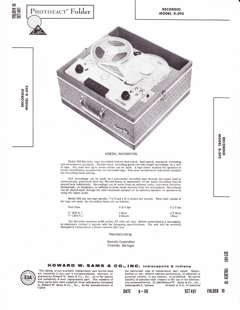
Recordio 220 User manual

rj:t --
e,cnt
r*l |l':t
el
-l l-
et frr
LV?
HOWAIID W. SAMS &
The lietlng of any available replacement part herein does
not conetitute in any case a recommendation, warranty or
guarantyby Howard W. Sams & Co. , Inc. , aa to the quality
and euitability of euch replacement part. The numbers of
these parts have been compiled from lnlormatlon furnlshed
to Howard W. Samg & Co. , Inc. , by the manufacturere of
cQ49l
R,ECORDIO
MODEL 22O
G (O.r I II G. lndlanapolls 6, lndlana
the particular type of replacement part listed. Repro-
duction or use, without express permission, of editorial or
pictorial content, ln any manner, ts prohlbited. No patent
liability is aeeumed vith reepect to the we of the lnforma-
tion contalned hereln. @ 1962 Howard W. Same & Co. , Inc. ,
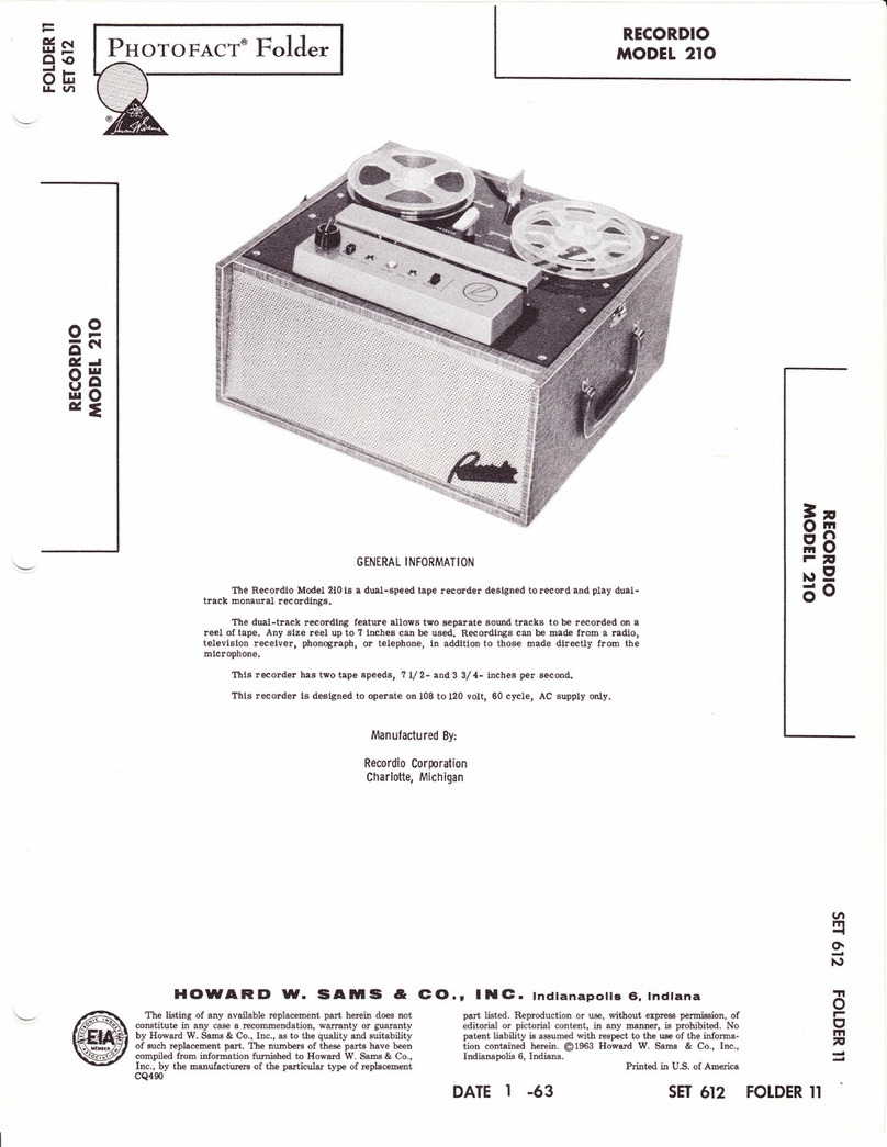
GENERAL INFORMATION
The Recordlo Model is a two-speed tape recorder. Thls unlt records and plays back
dtral-track monaural recordlngs.
The tape transport mechanism operates at 7L/2 and 3 3/4 ips. Any size reel up to
7 inches can be used
This recordio ls deslgned to operate on ll0-120 volts, 60-cycle, AC pov/er source.
Before connecting to an outlet, make certain ttrat the power source meets the foregoing
specificatlons. Severe damage willresult if connected to a higher voltage or to a direct (DC)
llne.
Manufactured By:
Recordio Corporation
Charlotte, Michigan
q
r?t
-l
CJI
CC'
-let
et
r-l
-
CJI
Indianapolis 6, Indiana.
oATt 10- 02
Printed in U.S. of Amerlca
sET 597 tot0tR
o
I
a
4
o
I
ut
4
rl
tll
o
o
=
v
ttt
t1
o
v
I
o

SUPPLY PAN SPEED CONTROL TAKE-UP PAN
TAPE
INDICATOR
RESET KNOB
REDI LITE
MONITOR -
TONE CONTROL OVERLOAD LITE
RECORD LOCK ON.OFF VOLUME
CONTROL
REWIND
RECORD A' STOP PLAY FAST FORWARD
PAGE 2FIG. I FRONT VIEW OF UNIT

Off -0n Volume
Clockwise rotation of this control turns the Re-
cordio I'ont' and regulates the volume for both the re-
cording and playback operations.
Tone-Speaker
Clockwise rotation of this control increases the
treble response. Also, when turned cloekwise frorn
the SPEAKER position, the speakers are muted when
the recorder is in the RECORD mode. Complete coun-
terclockwiserotationof tNs control provides a means
to monitor recordings.
Speed Control
The speed control knob should point to 7.50 or
3.?5 according to the speed desired. This Recordio
has twotape speeds, ?.50-inches per second and 3,?5-
inches per second. Insofar as quality of recording-
reproductionis concerned, speed is an important fac-
tor. The higher the speed, generally, the greater will
be the fidelity.
Caution: Do not turn the speed control knob unless
the STOP button is depressed.
Tape lndicator
Setthe TAPE INDICATOR to zero by turning the
knurled resetknob when startingto record or play back
areeloftape. Ifthe reading is noted at various points
in the tape travel, neur program selections can be in-
FUNCTIONS OF CONTROLS & PUSHBUNONS
OPERATI NG I NSTRUCTIONS
dexed, or previously recorded s elections can be located
with great accuracy.
Rewind Button
Thisbuttonisused to transfer tape rapidly from
thetake-upreel (right) to the supply reel (Ieft) at high
speed.
Record Button
Whendepressed, this button starts the Recordio
recording any sound fed to the tape from microphone,
radio, TV, phonograph, or telephone.
Note: THE "PUSH TO RELEASE" BUTTON MUST
BE PRESSED DOWN BEFORE THE RECORD
BUTTON CAN BE DEPRESSED.
Stop Button
Thisbuttonis usedto stop tape travel after being
ineitherthePLAY, RECORD, FORWARD, or REWIND
modes. Itis also asafety feature and must be pressed
down when the recorder is not in use.
Play Button
This button starts the Recordio playing back any
recording that is on the tape.
Forward Button
Thisbuttonisused to transfer tape rapidly from
the supply reel (left) to the take-up reel (right).
3a
95
FF
|\r9
8o
Preparing For Operation
1. Remove the AC power cord, reel of tape, empty
reel, and the microphone from the rear storage com-
partment.
2. Depress the STOP button.
3. Plug the AC cord into a convenient wall receptacle
of the proper rating.
4. Place the speed control knob in the 3.?5 or ?.50
position.
Caution: Donotturn speed control knob unless STOp
button is depressed.
When the forward (> ) or reverse (1) buttons
are depressed, the RECORD and PLAY buttons are
Iocked so they cannot be pressed down, with the pos-
sibilityof spilling tape. The buttons should always be
presseddownfirmlyuntilthey latch. The STOP button
mustbedepressedbefore changing functions or speeds
of the recorder.
Important: Always depress the STOP button when the
Recordio is not in use.
Threading The Tape
1. Placea reel of tape on the supply pan (Ieft) making
sure the reel slots catch the protrusions of the pan.
2. PIace an empty reel, the same si.ze or larger, on the
take-uppan (right). Again make certain the reel slots
catch the protrusions of the pan.
3. Releasethe STOP button by pressing lightly on any
one of the other buttons so that all buttons are in the
released position. This releases the tapebrakes, sim-
plifying tape threading.
4. Unwindaboutl4-inches oftape from the supply reel.
Hold a section straight with both hands and insert the
tape in the tape slot making sure the duII coated side
faces upward.
5. Insertthe free end of the tape into a slot in the hub
of the empty reel. While holdingthe tape in place, give
the reel tvo or three turns to secure the tape to the
reel.
To Record From Microphone
1. Insertthemicrophoneplug into the jack on the rear
panel labeled MIC.
o
t-
I
rrl
n
\tt
PAGE 3

2. With the STOP button depressed, turn the ON-OFF
VOLUME controltothe right (clockwise) until a "click"
is heard. Allow the recorder to warm up until the
REDI LITE is illuminated.
3. Place the speed control knob in the position de-
sired, As a general rule, 3.75-inches per second for
voice, and ?.50-inches per second for music.
4. Depress the PUSH TO RELEASE button with the
Iefthand and with the right hand depress the RECORD
button - then release the PUSH TO RELEASE button.
5. While holding the microphone about 3-4-inches away
from the mouth, speak in a normal tone of voice and
adjust the VOLUME control to the point where the
OVffi,LOAD indicator flashes at the louder or "peak"
passages.
Note: To monitor the sound being recorded, turn the
TONE-SPEAKER control to its extreme coun-
terclockrvise position. Care must be taken to
keep the microphone far enough from the re-
corder to prevent squeal due to acoustic feed-
back.
Rewind ( < ) 0r FastForward ( > )
When it is desirable to play a certain portion of
a tape over again, it is not necessary to rewind the
entire reel. By depressing the rewind ( < ) bution the
tape willreverse at a rapid speed. By depressing the
fast forward ( > ) button the tape will advance at a
rapid speed.
To Record From Radio 0r TV
Whileitis possible to record sound from an ex-
ternal source simplybyplacingthe microphone in front
of thespeaker, this is not recommended as background
noises willbe recorded alongwith the desired program
materials.
For noise free recordings, record directly from
the speaker voice coil terminals of the radio or TV re-
ceiver. For this purpose, a patch cord is available
from your Recordio dealer.
1. Inserttheplugof the patch cord into the jack on the
rear panel labeled iNPUT.
D ISASSEMBLY
To Remove Unit From Case
( Refer to Exploded View)
1. Remove push-on type volume and tone (14) control
knobs.
2. Remove two screws (16) located under volume and
tone control knobs. Remove front escutcheon (15).
3. Remove two hex-head screws (65) located under
front escutcheon.
4. Remove push-on type speed control lmob (3)'
PAGE 4
2. Connect the patch cord alligator clips to the radio
or TV receivers speaker voice coil terminals.
3. Adjust the volume control of the radio or TV to
normalroomvolume. Setthe tone control of the radio
or TV to full treble.
4. Proceedwithrecordingasdescribed under "To Re-
cord From Microphone".
To Record From Phonograph
1. Insert the phonograph output plug into the iack on
the rear panel labeled INPUT.
2. Start turntable and proceed with recording as de-
scribed under "To Record From Microphone".
Note: The microphone should not be connected to the
Recordiowhen recording from another source.
AIso, when the recording is played back, the
phonooutputcable should be removed from the
INPUT jack'
To Use Second Track
1. Depress the STOP button when the tape has been
wound onto the take-uP reel.
2. Removetake-upreel, tutnover, andplaceon supply
pan.
3. Place empty reel on take-up Pan.
4. Thread tape and proceed w.ith recording as pre-
viously described.
To Play Recordings
1. Thread tape as described under "Threading The
Tape".
2. Set the speed control knob to the speed at which the
recording was made,
3. Depress the PLAY button and adjust the VOLUME
and TONE controls for desired listening level.
I NSTRUCTI ONS
5. Removescrew(6) from knurled tape indicator knob
(?). Remove knob.
6. Remove screw (5) irom rear escutcheon (9). Re-
move rear escutcheon.
?. Remove tape indicator shaft and pointer assembly
(10).
8. Remove five Phillip's-head wood screws (21) from
front panel. Remove front Panel.
9. Remove two flat-head slotted screws from top of
cabinet,

Fig. 2. Front view of transport mechanism - f ront plate and escutcheons removed.
10. RemovetwoPhillip's-headscreril/sfrom each sub- 2. Unsolder motor leads from amplifier.
panel on rear of cabinet. 3. Disconnectthetwoleads from the play-record head
11. Lift tape transport and amplifier assembly par- terminals. Pull head leads through hole in baseplate.
tially out front of cabinet. Unplug two speaker leads
and remove AC cord clamp before removing unit com- 4. Remove two Phillip's-head machine screws from
pletely. each end of amplifier chassis.
To Remove Amplif ier From Transp0rt Mechanism 5. Carefullylifttheamplifier away from the transport
mechanism and disconnect the play-record switch act-
1. Remove seven hex-head sheet metal screws from uating link.
the amplifier bottom cover. Remove cover.
MEC HAN I CAL A DJ U STMENTS
3n
g5
FF
pg
Bo
Pressure Pad Adjustment
( Refer to Exploded View)
1. Remove front escutcheon (15).
2. Depressthe PLAYbutton. Donot turn the Recordio
tt ntt.
3. Useapencil-typepostalscale and check the amount
of pressure necessary to just puli the right-hand pad
awayfrom the play-record head (48). The test should
be made at the right-hand end of the pressure pad
mounting spring. If necessary, adjust locked adjust-
ment screril/ (33) until a reading ot L 3/4-oz. *l/4-oz.
is obtained.
4. The guide post pressure pad (left-hand pad) is ad-
justed by bending the pressure pad spring (26). Ad-
just for minimum pressure against tape.
Fig. 3. Erase head tape path.
Erase Head Adjustment
1. With tape properly threaded, turn recorder "on" J
anddepresstheRECORDbutton. Allow tape to run lor I
a few seconds, then turn recorder "off". Leave RE- E
\tl
PAGE 5
ERASE HEAD
I
r;=
t---ri
TAPE
I
I
CORD button depressed.

2. With front escutcheon (15) and rear escutcheon-(9) Bfake ShOe AdjUStment
removed, checkerase head (43) to see if it is parallel ( Refef tO EXplOded VieW)
with the tape. 1. Withall pushbuttons in the "up" position, the brake
3. Check to see if the top edge of the tape coincides pads (68) should clear brake drums (102 and 104) by
with the top end of the diagonal slot in the erase head approximately L/8,,.
(junctionof long diagonal slot and short vertical slot).
See Figure 3. To adjust the level of the tape, loosen 2. DepresstheSTOP button while observing the brake
set screw (35) and rotate tape guide post (36) to move pads. Both bral<e pads must contact the brake drums
tape up or down. See Exploded View. at the same time and with equal pressure.
3. If necessary, adjust by bending brake spring (8b).
CLEAN ING
The majority of defects, other than wear or accumulation should be periodically removed since it
breakage, can be traced to dirty surfaces. The play- will cause faint recording and poor playback. Wipe
recordhead(48),capstan,and pressure roller (58) are these surfaces carefully with a clean cloth. If dirt is
subjecttoanaccumulation of tape coating oxide, which caked and will not come off with a dry cloth, dampen
is worn off the tape as it passes these parts. This cloth with alcohol or lighter fluid.
LU BR ICATI ON
A11 rotating parts are paovided with generous 5. The reel pan bearing8.
size oilite bearings which are factory lubricated, Un-
der normal use no further lubrication is necessary. The basic rule is - do not over lubricate. Oil
In heavy duty service, the following parts should be must be kept off all rubber idlers, belts, and the per-
lubricated once a year with a drop of # 10 motor oil. iphery of fly$'heel and off parts that might trarsfer oi1
to them. Alnrays n'ipe excess lubricant from parts
1. The top and bottom motor bearings. that have been lubricated.
2. The capstan bearing, An occasiona.l cleaning of foreign matter from
under the pushbuttons is desirable, and a drop oJ oil
3. Pressur€ roller (58) bearing. on the sliding lever members is advieable,
4. AIL idler and drive wheel bearings.
PAGE 6
Fig. 4 Bottom view of tape transport mechanism.

Fig. 5. Bottom view of transport mechanism - motor mounting plate removed.
ELECTR I CAL ADJ U STMENTS
Play-Record Head Alignment
1. Remove timer escutcheon (9) and front escutcheon
(15).
2, Clean pole piece of play-record head (48) with al-
cohol or lighter fluid.
3. Thread alignment tape on recorder. Turn VOLUME
control to murimum and TONE control to fuII treble.
4, ConnectaVTVMto EXT. SPIG. jack. Set the meter
to AC, 3-volt scale. 2. Place unit in RECORD position and turn VOLUME
5. Place recorder in pLAY po€ition, ? l/2-inch per control to matdmum,
second tape speed, Decrease VOLIIME to point where
output is l-volton meter. Turn play-record head ad- 3. Corurect VTVM bet}'een ground and pin 1 of (V3),
justment 6crew (51) until maximum point of deflection Place meter selector on AC volts, 10V rarge.
on meter is obtained. 4. Adjust trimmer (C1Z) for a reading of 2_votts on
the meter.
TROU BLE CHART
Symptom Cause Remedy
Bias Adjustment
Turn the recorder "on" and depress the RE-
CORD button; use no tape. To determine if the bias
is with-in satisfactory limits without dismantling the
unit, connect a VTVM from the blue lead of the play-
record head to ground. If approximately 6b-volts are
present, no adjustment is necessary.
If an adjustment is necessary, proceed as follows:
1. Set line voltage at 11?-volts.
3a
95
Fn
t99
Bo
Push buttons fail to latch
into position. 1. Lock plate spring (73) disconnected or
broken. 1. Connect or replace
spring (73).
No drive in PIay or Re-
cord. 1. Idler tensionsprings (134) disconnected
or broken.
2. Idler slide plate (120) binding on bushing
(L22), thus preventing idler wheel (119)
from moving forward.
1. Connect or replace
springs (134).
2. Checkslide plate (120)
and bushing (122) for
burrs. Clean with al-
cohol.
T1
O
U
n
\JI
PAGE 7

A PHOTOFACT "EXPLODED" VIE\T
oHoward W. Sams & Co., lnc. 1962
PAGE 8
Fig. 6 A Exploded view of parts above baseplate.

\i i(
*=-.*:
E.-
A PHOTOFACT'EXPLODED' VIE\7
@Howard W. Sams & Co., lnc. 1962
H'
Fn
NEI
Bo
'Tt
O
1-
ct
m
n
\n
Fig. 6 B Exploded view of parts below baseplate.
PAGE 9

TROUBLE CHART ( CONT. )
Symptom Cause Remedy
Tape fails to wind on take-
up reel during Play or Re-
cord.
1. Reeldrivebelt (61) loose, disconnected,
or broken.
2. Reel pan shaft (2) binding.
1. Connect or replace
belt (61).
2. Clean foreign matter
from bearing surface and
shaft with a clean cloth.
Lubricate with one drop of
# 10 motor oil.
No Fast Forward or Re-
wind. 1. Idler lever tension spring (84) discon-
nected or broken, thereby not actuating
idler lever (89).
2. Idlerdrivebelt(115)broken or not pro-
perly connected.
1. Connect or replace
spring (84).
2. Replace idler drive belt
(1 1 5).
Tape spills when Stop but-
ton is depressed during
Fast Forward or Rewind.
1. Bral<e shoes out of adjustment.
2. Brale pads worn out or missing.
1. See "Brake Shoe Ad-
justment" under Mech-
anical Adjustments.
2. Replacebrakepads.
'\ilow" during operation
of recorder. 1. Brake return spring (80) disconnected
or broken.
2. Check all driving surfaces for oil or
foreign matter.
1. Connect or replace
spring (80).
2. Clean with a cloth and
alcohol.
"Flutter"duringoper-
ation of recorder. 1. Dirty play-record head (48), pressure
pads, capstan shaft, or pinch roller (58). 1. Clean asdescribed un-
der "Cleaning".
No erase or erase is in-
complete. 1. Erase head tension spring (31) discon-
nected or broken,
2. Erase head (43) not adjusted properly.
1. Connect or replace
spring (31).
2. See "Erase Head Ad-
justment" under Mech-
nical Adjustments.
Does not record 1. Faulty microphone or cord.
2. Faulty input jack.
Faulty tube.
Open play-record head (48).
1. Replace if necessary,
after checking recorder
with another type of input.
2. Check and replace if
necessary.
3. Check tubes.
4. Check continuity. Af-
ter checking fof con-
tinuity, demagnetize head.
3.
4.
Motor and amplifier in-
operative. 1. Power supply defect.
Damaged power cord,
Defective On-Off switch.
t
3.
1. Check voltages per
schematic.
2. Repair or replace.
3. Replace switch.
PAGE IO

MECHANICAL PARTS LIST
1
2
3
4
5
6
7
B
9
10
10A
11
t2
13
T4
15
16
1?
18
19
20
2l
22
23
24
25
26
27
28
29
30
31
32
33
34
c-13.318-6
c-13.318-6
73-2254-3
57-4C-624-5
5?-4C-405- 5
B-32.302-2
?3- 2334- 3
D-13.36 3- 1
B-26.619-2
B- 32.3?1
57-1 C-618-1
B- 28. 16 3
B-13.466-1
D-19.1?1 7
57-1 C-618-6
B- 13.46 5
B- 1 3.458- 1
B-1 3.458- 2
57 -44C-206-r
B- 33.41 2
7 3-2241-L4BF'
B- 19.868
B- 19.892
B- 31. 334
B- 31.334
5?-1 C-603-1
c-1 9.839- 1
B- 31. 361
48-41 0-1
5?-16C-606-1
B- 35. BB2- 1
5?- 3439-0
B-32.300
48-410- 1
B- 32. 26 0
B-3r.446-2
B-19.1410-1
57-168-61 3-0
73-2233-5
c- 35. ?56
B- 35.1278
57-1 C-603-1
73-223t-4
B-36.251
B-19.989
B-1 9.990
5?-16C-404-1
13-224r-t34
57-3439-0
Reel Pan & ShaJt Ass'y.
Reel Pan & Sha"ft Ass'y.
Speed Shift Knob
Felt Washer
# 6-32 xL t/2" o.H.M.S.
# 4-40 x 5/t6,, o.H.M.S.
Tinler Knob
# 6 Cantlink Washer
Timer Escutcheon
Timer Indicator
Timer Shaft
# 6-32 x 1 1/8" B.H.M.S.
Rear Escutcheon Plate
Linen Washer
Knob
Front Escutcheon
+ 6-32 x l l/8,, E}.H.M.S.
Indicator Window
Pushbutton (AIum.)
Pushbutton (Black)
Cabinet Cover Front Plate
# 2 x 3/B,,O.H.W.S.
Push-On Stud Nut, 3/16"
Flat Washer '
Playback Actuating Lever
Record Slide Plate
Pressure Pad Spring
Felt Pad, Play-Record
Head
Felt Pad
# 6-32 x 3/16 " B.H.M.S.
Playback Slide Plate
Erase Head Tension Spring
# 6-32 Hex. Nut
# 6-32 x 3/8,'R.H.M.S.
Record Actuating Lever
Ass'y.
# 6-32 x 3/L6" Bristol Hd.
Set Screw
Tape Guide Post (Left)
# 6-32 Hex. Nut
Tape Guide Post Spacer
Erase Head Return Spring
Erase Head Mtg. Plate
# 6-32 x t3/L6,,R,H.M.S.
# 6 Int. Lockwasher
Erase Head Ass'y.
Pinch Roller Plate Ass'y.
+ 6-32 x 3/t6" B.H.M.S.
# 6 Int. Lockwasher
Tape Guide Lug
Play-Record Head
Play-Record Head Mtg.
Bracket
Spring, Play-Record Head
# 4-40 xl/4,,R.H.M.S.
Flat Washer
# 6-32 x 3/16" Bristol Hd.
Set Screw
Tape Guide Post (Right)
Pinch Roller Tension Spr
"E" Ring, 3/16" Shaft
Linen Washer
B-33.404
B-16.104
B- 28. 1 ?5
5?- 3439-0
5?-608-616-1
B- 33.446
57-1 C-603- 2
13-223r-4
48-22t9-r
B- 19.876
B-1 9.859
B- 31. 33?
B- 31.343
73-2231-5
5?-6C- 806- 1
13-2231-5
57-6 C- 805- 1
B- 35.1046
B- 31. 338
B- 35.835
73-224t-t48F
48-222r
B- 31. 339
8.35.1 070-1
B- 31.335
73-2340-l
13-2248-39
B- 35. i051
B-32.215-r
B- 35.1452
5?- 3698-0
B- 31.333
B-33.118
7 3-223r-4
5?-1 C-603-2
7 3-223t-4
5?-1 C-614-1
D-33.445
c-1 3.257-1
57-3589-1
c- 35.1050- 1
5?- 3589- 1
c- 35.1050- 1
5? - 3589- 1
B- 35.1 044
B-32,215-t
B- 28.16 3
58
59
60
61
62
63
64
65
66
6?
68
69
?0
7l
12
73
14
75
?6
Pinch Roller
Shim Washer, Brass
Baseplate & Bearing Ass'y.
"O" Ring
# 6-32 x 3/16" Bristol Hd.
Set Screw
#6x1"H.H.S.M.S.
Spacer
# 6-32 x 3/16,'B.H.M.S.
# 6 Int. Lockwasher
#6-32x5/16" Keps Hex.
Nut
Pushbutton Lever
Pushbutton Hinge Bracket
Pushbutton Return Spring
Lock Plate Spring
# 8 Int. Lockwasher
# B-32 x 3/8,,R.H.M.S.
Record Interlock Spring
Ass'y.
# 8 Int. Lockwasher
# 8-32 x 5h6,,R.H.M.s.
Shift Plate Ass'y.
Brake Return Spring
Brake Slide Plate Ass'y.
Flat Washer
# 10-32 Elastic Stop Nut
Idler Lever Tension Spring
Brake Spring Ass'y.
Brake Pad, FeIt
Varnish Impr egnated Washer
Phenolic Washer
Idler Lever Ass'y.
# B-32 Hex. Hd. Shouldered
Screw
Switch Lever Ass'y.
# B-32 x 3h6" Bristol Hd.
Set Screw
Switch Arm Link
Spacer for Gear Train
# 6 Int. Lockwasher
# 6-32 x 1/8,, B.H.M.S.
# 6 Int. Lockwasher
# 6-32 x 7 /8,, B.H.
Gear Train for Tape
Indicator
Fly'wheel
# 8-32 xl/4', Bristol Hd.
Set Screw
Brake Drum & Bushing
Ass'y.
# 8-32 xl/4,,Bristol Hd.
Set Screw
Brake Drum & Bushing
Ass'y,
# B-32 x t/4,, Bristol Hd.
Set Screw
Sub Idler Plate Spring
Sub Idler Plate Ass'y.
# B-32 Hex. Hd. Shouldered
Screw
Linen Washer
77
7B
?9
BO
B1
82
B3
84
B5
B6
8?
oo
89
90
102
3n
96
F-
|.)9
Bo
36
3?
38
39
40
4L
42
43
44
45
46
47
48
49
91
92
93
94
95
96
97
98
99
100
101
106
10?
108
103
104
105
5i
52
53
54
55
56
B- 32.309
B-31.360
B- 33.418- 2
B-28.16 3
-T.t
O
|-
(f
rn
v
\,l
Description
--t-
109
PAGE I 1

MECHAN ICAL PARTS LI ST CONT.
Description
Description
110
111
tL2
113
,tL4
115
iro
117
,1 18
119
t20
t2l
r22
t23
r24
t25
L26
L27
t28
129
130
B- 33.405
73-2254-6
B- 33.418- 2
B-28.163
B- 35.1066
B- 28.181
B-33.418-2
B- 32.288
57- 3589- 1
B- 33.408
B- 35.1064-1
57-6C-806-1
73-2231-5
73-224r-L43
B-19.1431-1
r--32.291-1
B- 31.327
B-33.40?-1
5?-1 C-603-1
Sub Idler
Felt Washer
"E" Ring, 3/\6" Shaft
Linen Washer
Sheave Pulley Ass'y.
Idler Drive BeIt
"E" Ring, 3h6" Shaft
Motor Pulley
# 8-32 x Lf 4" Bristol Hd.
Set Screw
Rubber Bonded Idler,
2 L/2" Dia.
Idler Slide Plate Ass'y.
# 8-32 x g/t6" R.H.M.S.
Idler Slide Bushing
# 8 Int. Lockwasher
Flat Washer
FIat Washer
Idler Throw-Out Lever
Shouldered Washer
Idler Lift Compression
Spring
"C" Washer
# 6-32 x 3h6" B.H.M.S.
73-223r-4
B-19.961
c- 35.816- 1
B- 31. 324
B- 19.862
73-2231-5
5?-6C-805-1
B- 19. 86 3
73-2231-5
57-6C-805-1
57-6 C- 805- 1
B- 35.1054-2
B- 28.181
B- 28. L94-2
D-36-153
48-2221
B- 33.534
57 - 3698 -0
B- 33.643
# 6 Int. Lockwasher
Spring Clip
Speed Control Shaft Ass'y.
Idier Tension Spring
Angle Brkt. for Mtg. Drive
Ass'y.
# 8 Int. Lockwasher
# 8-32 x 5/t6" R.H.M.S.
Drive Mtg. Plate Bracket
# 8 Int. Lockwasher
# 8-32 x 5/16" R.H.M.S.
Drive Mtg. Plate Ass'y.
Idler Drive Belt
Motor Mtg. Plate
Shock Mount
Motor
Anti-Shock Bracket
# 10-32 Elastic Stop Nut
Anti-Shock Grommet
Nylon Cable Clamp
# 8-32 x 3h6" Bristol Hd.
Set Screw
4" Fan Blade
131
132
133
134
135
136
137
138
139
140
t4l
142
143
t44
t45
146
r47
148
t49
150
151
152
FIG. 7
TOPVIEW OF
MOTOR MOUNT
PLATE ASS'Y.
6X4 6AQs 6AV6 12AX7
It a
w
l:r:
F**;*Y
,"/ *
FIG. 8 ANlP CHASSIS -TOP VIIW
PAGE I2

9 AMP CHASSIS BOTTOM VIEW.CAPACITOR &MISC IDENT.
FIG. IO AMP CHASSIS BOTTOMVIEW.RESISTOR &INDUCTOR IDENT.
3z
g5
Fv
roP
Bo
o
tr
rrl
n
\Ji
PAGE I3

OR
E:
gr
c,t
E
=p
!r\ Cl
]\F
3E
== --
q)
(l)-G,
€g Ess E
= €€ sEAgF
F ;i g E s,nEi
1> =:: EtE 8s
EF : eE:; eEIa
2= E5:_-iE F i
-;e !E s=-! E
9* E: = H= B F g
€=iE;aPE
E g E HEE i E
EEE€ EEti
eCges'E;E
;;gECEE:
--; e.i,.i + .i €;
6Lz
z>o
<o^
.^-o = u
Y-)+= F
L!OO
.\ZU-
6= g=H ;
=: @6r I
s: g#*A H g
iz. -:*6 Z!
git rEu ?'.
=Eft =tE eg
a;x6 ;= = ?E
=E13 EEi 2>
.*!i Eti Ii
nc 9-U qi
tr6 nfr9 $o
1- <Eft O
;? fiEE= e
e- =EF= :
E
o
co
@
s
E
o
-r
o., Z.
,e. oo
o
lfj
&,
lrl
=
-J
€
L!
(J
e.
c)
at
c
ott
oE
I\
+9
AE
Fat
T
@
Ld
()
d,
)
o
Lll
c
oB
l\ (\
-l
o
c
c.{
@,
ci
UJ
C)
d
=
o
vr
o
\
6t
tt
(9
z,
(f
lrl
e
lIJ
(J
z
F
att
6
lr!
E
at
Flfl
6tt
o
dO
5-l
Lid
zlLt
o
EF
i\ t9
@
3E
e;
c
rn
(Y\
_@
E
EEe
oc)
@
trl
F
dJ
!nl
=A
- trt
d.
z,
O
z.-
Y==
90t/,
-*=8
>^-
{cvb
dEe
r -O
o-()
59-P
H=;
e. Lrt =
@
=
!lo
a_o
o
F
o
?
{Hl
@
rZ
o
AI
@
rz
o
€
@
o
ct
(\t
''dl'
E
c
O
o
{Ht,'
6\
g/
E@
v.
o
€
\o
A
\y
--,
(-)o
,-- &,
72.
vlO
oa cJ
PH
*o
2.ts-
O-
=5
f.\
@
@
p>
Foe\
I
E
o
6J
RI
-{Hl''
6\
(-+/
\z
o
o
tt\
@
o-
F
o
@
F
=
o-
=
d
=
R 5A
";
@
@
@
q
3=
$-
A
\y
aE
\Ob
@
o
@
o
o
c\
l,
J
o\
p
I
T
rr)
.a
5<
=\O
5\
oo\o\
J
tlt
o(9)
o \-/
e
I'1
\o
=s
ks
B
e
Ht,'
@
o
(a
@
I
I
^ tlt
=N
HI
(\l
e
* <tl
EO
d(J
F(J
?:U
AN
.ox
2<
6NE
e
e
V
o-
vt
F
x
rlJ
@
E
E
o
F
=
(.)
d,
6
U
!
.F
az.
t4J -
L
k(-)
z.=
<c!
--Jatt
HE
ur. (-)
:35
=il
u-!
-F
F l,!
oo
ar1 z,
ttl O
uJ-
JF
=a
=7q) C-)
FE
tt, l-
Rg
=cL
)--
JC5
o-z
=-
2.9
lrJ
zo-
Ul lfJ
\26
s>
'e.
!1 <.
2>
l4l J
=-r
H=
ol
lrl Cl
E<
gH
<. vt
l--
l-
oF
-lJ
<rF
PAGE T4

AMP PARTS LIST AND DESCR,IPTIONS
WIRING DATA
General-use Unehielded Hook-up Wire ... ....... Use BELDEN No.
POVET COrd U8e BELDEN No.
Power Cord (Interlock Type) .. . Use BELDEN No.
Lo\y-Loss Shielded Lead (Interconnecting) . .. ,. . , Uee BELDEN No,
Phono Pick-up Arm Ca.ble ..... Uee BELDEN No.
8530 (Soiid) Avaiiable ln 12 Colorg
8524 (Stranded) Available in IZ Colorg
i7106 (Plastic) or 17126 (Rubber) - 6 Ft.
17109 (Plaetic) or 17129 (Rubber) - 9 Ft.
8874 (Rubber) or 8895 (Plastic)
8401 or 8421
8430 (Two Conductor-Unehielded)
8429 (Two Conductor-Shielded)
8419 (Three Conductor-Shielded)
AMPEREX - GENERAL ELECTRIC - RAYTHTON - SYLVANIA
Preamp. -Blas Osc.
AF Amplifier r2Ax?/Ecc83
EBC9I/6AV6
ETECTROLYTIC CAPACITORS
ITEM
No
RATING REPTACEMENT DATA
CAP. VOLT. RECORDIO
PART No. AEROVOX
PART No- coRNEr-t.
DUBII,IER
PART No.
GENERAI"
EIECrRrC
PART No- MAII.ORY
PART No. PYRAI\AlD
PART No. SPRAGUE
PART No.
ctA
B
c
c2a
E
.30
^30
30
l0
10
250
250
25
200
200 )"u.nr'' (
85.444 PRS2300 BBRDTT4S
80220
BBR25-25
QTz.3
FP32l.5
TCS52
TMT3432
TDLD-26
TVLS-3513,2
TVA-2122
FIXED CAPACITORS
ITEM
No. RATING REMARKS REPTACEMENT DATA
AEROVOX
PART No. PART No.
,UXNELL.
}UBI[IER
ao? tr^ ELMENCO
PAPT N^ MATTORY
PART Na SPRAGUE
PART No.
c3
c4
c5
c6
c7
c8
c9
c10
cu
CL2
c13
c14
ct5
c16
CI?
cr8
cr9
c20
c2I
c22
820 tqo
410 Lqo
.04? 200v
.0r
.00r
.0I
.01
470
I00
.003
100
.01
.004? 600v
229
J -JC
.0I
.047 600v
220 Lqo
5-70
.0015
#B-4.L44
#B-4. 146
Note I
1469-00082
1469-00047
P2 8 8N-04 7
BPD-OT
sI 1000
BPD-OI
BPD-Ot
Dr-470
Dt-100
DI-3000
DI-100
BPD-OI
P688N-004?
Dt-220
BPD-OI
P688N-04?
146 I -00022
1500
SI
DD-503
DD-IO3
D6-102
DD-IO3
DD-IO3
DD-471
DD.IOI
DD-302
DD.IOl
DD-103
D6-472
DD-22I
DD-i03
DD-503
TCZ-220
D6-152
bRbT82
5R5T47
cu82s47
BYAIOSI
BYAIODI
BYAIOSI
BYAlOSI
BYAlOT47
LIOTI
BYAIOD3
LlOTI
BYAIOSI
CU86D47
LIOT22
BYAIOSI
CUB6S4?
22R5T22
BYAIODIS
cM-198-82lK
cM-I9B-471K
4DP-3 -473
ccD-103
ccD-102
ccD-103
ccD-103
ccD-471
ccD-101
ccD-302
ccD-l0I
ccD-r03
6DP-l-472
ccD-221
402
ccD-103
6DP-3 -4?3
cM-l9B-22IK
462
ccD-152
MC8251
MCJ244
GEM-4I4?
B-I]O
B-210
B-IIO
B-I1O
B-34?
3P310
3P230
f,p310
B-I1O
IEM-6247
iP322
3-IIO
tEM-6i4?
,-NO-322
l-2I5
MS-382
MS-34?
2TM-S4?
5HK-Si0
5HK-DIO
5HK-St0
5HK-SIO
lOTs-T47
IOTS-TIO
l0TS-D30
l0Ts-Tl0
5HK-SIO
6TM-D47
IOTS-T22
5HK-Sl0
6TM-S4?
MS-322
5HK-Di5
* Not normally in dlstributor'!s stock. Available thru distfibutor on ofder to manufacturer.
# Recordio Part Number.
Note I. Not used in some versions coNTROtS
All wattages l/2wdtl, or less, unless otherwise listed
3-
95
F7
l\)g
Bo
tt
o
F
I
lll
v
l'll
t5
ITEM
No. USE RESIST-
ANCE
REPTACEMENT DATA
RECORDIO
PART No. CENTRALAB
PART No. CLAROSTAT
PART No. cTs - tRc
PART No. MATTORY
PART No.
RI
R2
Volume & Power Sw.
Tone & Monitor Sw.
lmeg
500K Tap
250K
c-8.221-24
c-8.249-l€)
BT-?4, I(R-I,
(ABT-74, KR-1"
AK-7)
B-5I, KR-15
(AB-51, KR-1,
AK-?)
A47F5-Imeg/
FS-3, SWE
441-250IK-Z,
swE-12, FS-3
QIg-137X, ?6 -I,
(BUI, C F47T,
ssl, Gc) t
Qr3-t30,76-I,
(BUt, cF23, ssr,
Gc) t
uT443, US-26,
(uA16T454, US-4
sL-3500)
u44, us-26,
(uA2544, uS-41,
sL-3500)
O Alternete Part #C-8.227-17.
@ Alternate part #C-8.249-2.
T ''SNAPTROL''.
PAGE

AMP PARTS tlST AND DESCRIPTIONS (Continuedl
RESISTORS
All wattages lf?wtrl, or less, unless otherwise listed.
REPLACEMENT DATA
REPTACEMENT DATA
R3
R4
R5
R6
R?
R8
R9
RIO
Rll
RI2
Rt3
R14* Alternate.
Note l. Not used in some versions. cotls (RF-!F)
TRANSFORMER (AUDIO OUTPUT)
ITEAA
No- usE
REPLAC MENT DATA NOTES
RECORDIO
PART No. Merit
PART No. Miller
PART No. Sloncor
PART No- Workmon
PART No.
LI Bias Osc.
TRANSFORMER (POWER)
ITEM
No. RATING NT DATA
NOTES
RECORDIO
P.ART No. Merit
PART No. Sloncor
PART No. Thordo rson
PART No. l ilod
PART No.
PRI sEc_ IsEc.
T] uTvAc
.26A 440VCT
@.040A 6. ?VAC
o l.6A c -9.28r
ITEM
No. IMPEDANCE REPLACEMENT DATA NOTES
RECORDIO
PART No. Merit
PART No. Sloncor
PART No. Thordorson
PART No. Triod
PART No.
PRI. sEc_
T2 5500f, 3-40 c -9. 264 A-2935 A-38?7 24S5r s-bx
SPEAKER
ITEM
No- TYPE REPLACEMENT DATA
NOTES
RECORDIO
PART No. QUAM
PART No.
SIZE FIELD v. c. tMP.
SPI
sP2 4'x 6"
4'rr 6" PM
PM 6-8f,
6-8f' c-30.354-2
c-30.354-2 46407z'6,4
46A07z,6.4
MISCELLANEOUS
ITEM
No. PART NAME RECORDIO
PART No. NOIES
l/tr
\n IIead
Switch B-36" 251
B-11" 24? Record - Playback
Record-Playback (Rotary Wafer Type)
PAGE T6
Table of contents
Other Recordio Voice Recorder manuals