Red Arrow PC10A User manual
PAGE 2 (TWO - INSIDE DPS)
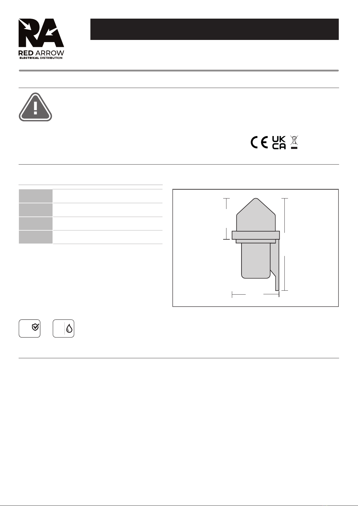
Photocells
Product Codes: PC10A, PC10AH
Box Contents -
1 x PC10A - Photocell Kit
1 x PC10AH - Photocell Head
Dimensions: PC10A: L: 130 x Ø: 80mm
PC10AH: L: 64 x Ø: 80mm
Material: Polycarbonate
IP Rating: IP65
Guarantee: 1 year
Safety Warning
• The installation should be carried out
by a qualied electrician in compliance
with the current edition of the IEE
Wiring Regulations.
• Prior to installation, carry out the
necessary risk assessment considering
the people who could be at risk,
the level of risk and the precautions
required to control the risk
• Ensure that the circuit supply is
isolated either by the circuit supply
fuse being removed or the applicable
circuit breaker being turned o before
installation or any maintenance.
• Check the total load on the circuit
ensuring the luminaire does not exceed
the rating of the circuit cable, fuse or
circuit breaker.
• Long-term use and voltage uctuations
can reduce the life span of the tting.
• If the tting incorporates control gear,
ensure careful sizing to avoid instances
of nuisance tripping of the protective
device used in the installation.
• Follow the provided installation
instructions, using the xings supplied
or recommended.
• Keep out of reach of children.
IP65
1
YR
GUARANTEE
INSTALLATION INSTRUCTIONS
PAGE 1 (FRONT PAGE)
Specication
1. Carefully choose the correct position to install the photocell kit considering the following guide lines:
• Where possible there should be a clear view of the sky, allowing sucient distance when mounting under eves.
• For optimum performance the position chosen should have a clear view of north.
• Be away from view of any articial light source.
• Be away from view of the light source the unit is to control.
2. Securely x the base holder to a vertical wall so that the head will be facing up when tted.
3. Fit the gasket into the base holder foam side up.
4. Enter the supply & load cable into the base through the hole in the bottom of the base ensuring that a cable gland grommet or sealing compound is used
to maintain the IP rating of the unit.
5. Terminate the cable into the Nema socket observing the correct connections;
“li” = live (supply in)
“lo”= load (supply out)
“n” = neutral (the neutral to the load does not need to pass through the unit and can be taken directly).
6. Place the Nema socket into the base holder with the arrow printed on the socket pointing towards north. If north is located behind the unit towards the
mounting surface then the arrow should be aligned pointing in the direction of best natural light.
7. The base holder has 2 locating pins for the Nema socket to t onto, the Nema socket should then be secured using the 2 counter sunk self tapping screws
provided.
8. Align the largest of the 3 brass feet marked ‘neutral’ on the photocell head with the largest slot in the nema socket, push the photocell head into the Nema
socket and gently turn clockwise to lock into place.
Installation Instructions
Ø80mm
W64mm
W130mm

INS/ACCESSORIES/0001/PC10/V4
T: 0800 195 0006
sales@redarrowelectrical.co.uk
Red Arrow Electrical Distribution
Cortonwood Drive, Brampton,
Barnsley, S73 0UF
redarrowelectrical.co.uk
PAGE 2 (TWO - INSIDE DPS)
This product is guaranteed for a period of 1 year from the date of purchase. The guarantee is invalid in the case of improper use, tampering, removal of the Q.C.
date label, installation in an improper working environment or installation not according to the current edition of the I.E.E. Wiring Regulations (BS7671). The
guarantee is also invalidated if the luminaire has been insulation tested. Should this product fail during the guarantee period it will be replaced free of charge,
subject to correct installation and return of the faulty unit. We do not accept responsibility for any installation costs associated with the replacement of this
product. Your statutory rights are not aected. We reserve the right to alter specications without prior notice.
• This tting will require routine cleaning if used in adverse (dust, paint, welding, oils etc) environments. Do not use solvents, aggressive detergents or
abrasives.
• When this tting comes to the end of it’s life or you choose to replace it, please do not dispose of it with your normal waste. Please recycle where the
facilities exist, check with your local authority for suitable options.
PAGE 1 (FRONT PAGE)
Guarantee
Maintenance
• The photocell always powers up in the“on”position, if in bright daylight it will switch o within 2 minutes.
• To test for correct operation cover the photocell with the packing box, after a short delay, 15-120 seconds, The photocell will operate and power will be
applied to the load. If tested in bright daylight after a similar delay the photocell will turn o the power to the load when the packaging box is removed.
Operation & Testing
• The load stays on:
The photocell is in a shady or dark position.
The neutral is not connected.
• The load is ashing, strobing or switching on and o repeatedly through hours of darkness:
The photocell is too close to the light source it is controlling.
“li” & “lo” are reversed.
Common Problems
This manual suits for next models
1
Table of contents
Other Red Arrow Accessories manuals


