TM-229 409 Page 1
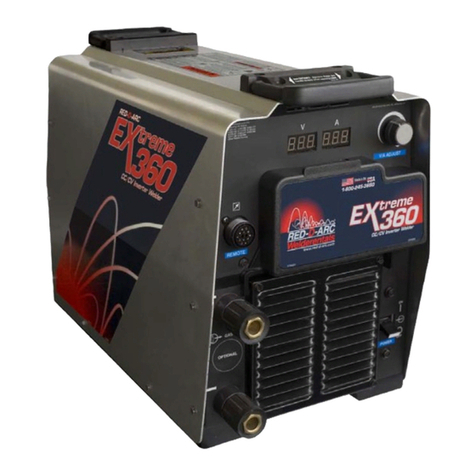
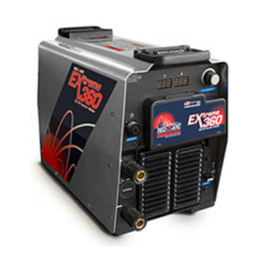
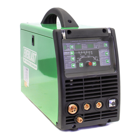
Extreme 360
SECTION 1 −SAFETY PRECAUTIONS FOR SERVICING
1-1. Symbol Usage
OM-229 409-B, safety_stm 8/03
Means Warning! Watch Out! There are possible hazards
with this procedure! The possible hazards are shown in
the adjoining symbols.
YMarks a special safety message.
.Means “Note”; not safety related.
This group of symbols means Warning! Watch Out! possible
ELECTRIC SHOCK, MOVING PARTS, and HOT PARTS hazards.
Consult symbols and related instructions below for necessary actions
to avoid the hazards.
1-2. Servicing Hazards
YThe symbols shown below are used throughout this manual to
call attention to and identify possible hazards. When you see
the symbol, watch out, and follow the related instructions to
avoid the hazard.
YOnly qualified persons should service, test, maintain, and re-
pair this unit.
YDuring servicing, keep everybody, especially children, away.
ELECTRIC SHOCK can kill.
DDo not touch live electrical parts.
DTurn Off welding power source and wire feeder
and disconnect and lockout input power using
line disconnect switch, circuit breakers, or by removing plug from re-
ceptacle, or stop engine before servicing unless the procedure spe-
cifically requires an energized unit.
DInsulate yourself from ground by standing or working on dry insulat-
ing mats big enough to prevent contact with the ground.
DDo not leave live unit unattended.
DIf this procedure requires an energized unit, have only personnel
familiar with and following standard safety practices do the job.
DWhen testing a live unit, use the one-hand method. Do not put both
hands inside unit. Keep one hand free.
DDisconnect input power conductors from deenergized supply line
BEFORE moving a welding power source.
SIGNIFICANT DC VOLTAGE exists after removal of
input power on inverters.
DTurn Off inverter, disconnect input power, and discharge input
capacitors according to instructions in Maintenance Section before
touching any parts.
STATIC (ESD) can damage PC boards.
DPut on grounded wrist strap BEFORE handling
boards or parts.
DUse proper static-proof bags and boxes to
store, move, or ship PC boards.
FIRE OR EXPLOSION hazard.
DDo not place unit on, over, or near combustible
surfaces.
DDo not service unit near flammables.
FLYING METAL can injure eyes.
DWear safety glasses with side shields or face
shield during servicing.
DBe careful not to short metal tools, parts, or
wires together during testing and servicing.
HOT PARTS can cause severe burns.
DDo not touch hot parts bare handed.
DAllow cooling period before working on welding
gun or torch.
EXPLODING PARTS can cause injury.
DFailed parts can explode or cause other parts to
explode when power is applied to inverters.
DAlways wear a face shield and long sleeves
when servicing inverters.
SHOCK HAZARD from testing.
DTurn Off welding power source and wire feeder
or stop engine before making or changing me-
ter lead connections.
DUse at least one meter lead that has a self-
retaining spring clip such as an alligator clip.
DRead instructions for test equipment.
FALLING UNIT can cause injury.
DUse lifting eye to lift unit only, NOT running
gear, gas cylinders, or any other accessories.
DUse equipment of adequate capacity to lift and
support unit.
DIf using lift forks to move unit, be sure forks are
long enough to extend beyond opposite side of
unit.
MOVING PARTS can cause injury.
DKeep away from moving parts such as fans.
DKeep all doors, panels, covers, and guards
closed and securely in place.
