manuals.online logo
Brands
  1. Home
  2. •
  3. Brands
  4. •
  5. red lion
  6. •
  7. Media Converter
  8. •
  9. red lion GCM23201 User manual

red lion GCM23201 User manual

1
!ALLOWS COMMUNICATIONS BETWEEN RS-232 CONTROL
EQUIPMENT AND RLC PRODUCTS WITH 20 mA SERIAL
COMMUNICATIONS OPTION
!ISOLATED 20 mA SERIAL COMMUNICATIONS
!FULLY ENCLOSED SCREW-TOGETHER DURABLE PLASTIC
CASE
DESCRIPTION
The GCM232 Serial Converter Module provides the capability of interfacing
Red Lion Controls products with 20 mA current loop serial communications
option to most equipment with RS-232 communications. The isolated 20 mA
current loop connections in the GCM232 allows multiple modules to be wired
into the serial loop. Data format of the RS-232 equipment must be the same as
the Red Lion Controls product (Reference the serial communications section of
the appropriate manual for more details).
An external +12 VDC power source is required to power the GCM232
module. Some Red Lion Controls products have a +12 VDC output which can
be used (Note: Reference appropriate manual to ensure +12 volt output has
enough current capability). The external power source and isolated 20 mA
serial communications loop connections are made via a 6 position terminal
block located inside the module. A 680Ωcurrent limiting resistor is provided to
obtain the source current for the Serial Current Loop. Connections for the RS-
232 are made via a 25-pin female D-type connector.
SAFETY SUMMARY
All safety related regulations, local codes and instructions that appear in the
manual or on equipment must be observed to ensure personal safety and to
prevent damage to either the instrument or equipment connected to it. If
equipment is used in a manner not specified by the manufacturer, the protection
provided by the equipment may be impaired.
SPECIFICATIONS
1. POWER: + 9 to 28 VDC @ 30 mA max.
Power supplies must be Class 2 or SELV rated.
2. RS-232 VOLTAGES:
Receive Data Pin 2: ± 30 VDCmax., mark condition < 0.8 VDC
space condition > 2.4 VDC.
Transmit Data Pin 3: mark condition = -10 VDC (typ).
space condition = +10 VDC (typ).
3. 20mA CURRENT LOOP:
SO - Output Transistor Rating: Vmax = 25 VDC,
Vsat = 1 VDCmax @ 20 mA.
SI - Input Diode Rating: VF = 1.25 VDCtyp, 1.5 VDCmax @ 20 mA.
(Note: Reverse polarity protection at SI diode)
4. MAXIMUM CABLE LENGTH:
RS-232 cable: 50 Ft.
20 mA current loop: 4000 Ft.
5. BAUD RATE: 9600 max.
6. ENVIRONMENTAL CONDITIONS:
Operating Temperature: 0 to 50°C
Storage Temperature: -40 to 80°C
Operating and Storage Humidity: 85% max. (non-condensing) from 0°C
to 50°C.
Altitude: Up to 2000 meters
7. CERTIFICATIONS AND COMPLIANCES:
SAFETY
IEC 1010-1, EN 61010-1: Safety requirements for electrical equipment
for measurement, control, and laboratory use, Part 1.
EMC EMISSIONS:
Meets EN50081-1: Residential, Commercial and Light Industry
CISPR 22 Radiated and conducted emissions
EMC IMMUNITY:
Meets EN 50082-2: Industrial Environment.
ENV 50140 - Radio-frequency radiated electromagnetic field 1
ENV 50141 - Radio-frequency conducted electromagnetic field 1
EN 61000-4-2 - Electrostatic discharge (ESD)2
EN 61000-4-4 - Electrical fast transient/burst (EFT)3
Notes:
1. For operation without loss of performance:
Install power line filter, RLC #LFIL0000 or equivalent.
I/O cables routed in metal conduit connected to earth ground.
2. Anti-static precautions should be observed before handling the device.
3. For operation without loss of performance:
Install power line filter, RLC#LFIL0000 or equivalent.
Refer to EMC Installation Guidelines section of the manual for additional
information.
8. DIMENSIONS: 0.99" H x 2.10" W x 4.32" L
25.2 mm H x 53.4 mm W x 109.8 mm L
9. Shielded cable must be used, connect shield drain wire to earth ground.
MODEL GCM232 - SERIAL CONVERTER MODULE (RS-232C/20 mA CURRENT LOOP)
ORDERING INFORMATION
MODEL NO. DESCRIPTION PART NUMBER
GCM232 Serial Converter Module RS-232 GCM23201
CAUTION:
Read complete instructions prior to
installation and operation of the unit.
Bulletin No. GCM232-I
Drawing No. LP0214
Released 6/01
Tel +1 (717) 767-6511
Fax +1 (717) 764-0839
www.redlion-controls.com
Courtesy of Steven Engineering, Inc.-230 Ryan Way, South San Francisco, CA 94080-6370-Main Office: (650) 588-9200-Outside Local Area: (800) 258-9200-www.stevenengineering.com
EMC INSTALLATION GUIDELINES
Although this unit is designed with a high degree of immunity to
ElectroMagnetic Interference (EMI), proper installation and wiring methods
must be followed to ensure compatibility in each application. The type of
electrical noise, source or coupling method into the unit may be different for
various installations. In extremely high EMI environments, additional measures
may be needed. Cable length, routing and shield termination are very important
and can mean the difference between a successful or a troublesome installation.
Listed below are some EMC guidelines for successful installation in an
industrial environment.
1. DC power to the unit should be relatively clean and within the specified
limits. Connecting power to the unit from circuits that power inductive loads
that cycle on and off, such as contactors, relays, motors, etc., should be
avoided. This will reduce the chance of noise spikes entering the DC power
connection and affecting the unit.
2. The shield (screen) pigtail connection should be made as short as possible.
The connection point for the shield depends somewhat upon the application.
Listed below are the recommended methods of connecting the shield, in
order of their effectiveness.
a. Connect the shield only at the unit to earth ground (protective earth).
b. Connect the shield to earth ground at both ends of the cable, usually when
the noise source frequency is above 1 MHz.
c. Connect the shield to common of the unit and leave the other end of the
shield unconnected and insulated from earth ground.
3. Never run Signal cables in the same conduit or raceway with AC power lines,
conductors feeding motors, solenoids, SCR controls, and heaters, etc. The
cables should be run in metal conduit that is properly grounded. This is
especially useful in applications where cable runs are long and portable two-
way radios are used in close proximity or if the installation is near a
commercial radio transmitter.
4. Signal cables within an enclosure should be routed as far away as possible
from contactors, control relays, transformers, and other noisy components.
5. In extremely high EMI environments, the use of external EMI suppression
devices, such as ferrite suppression cores, is effective. Install them on Signal
cables as close to the unit as possible. Loop the cable through the core several
times or use multiple cores on each cable for additional protection. Install
line filters on the power input cable to the unit to suppress power line
interference. Install them near the power entry point of the enclosure. The
following EMI suppression devices (or equivalent) are recommended:
Ferrite Suppression Cores for signal cables:
Fair-Rite # 0443167251 (RLC #FCOR0000)
TDK # ZCAT3035-1330A
Steward #28B2029-0A0
Line Filters for input power cables:
Schaffner # FN610-1/07 (RLC #LFIL0000)
Schaffner # FN670-1.8/07
Corcom #1VR3
Note: Reference manufacturer’s instructions when installing a line filter.
6. Long cable runs are more susceptible to EMI pickup than short cable runs.
Therefore, keep cable runs as short as possible.
INSTALLATION ENVIRONMENT
The unit should be installed in a location that does not exceed the
maximum operating temperature and provides good air circulation. Placing
the unit near devices that generate excessive heat should be avoided.
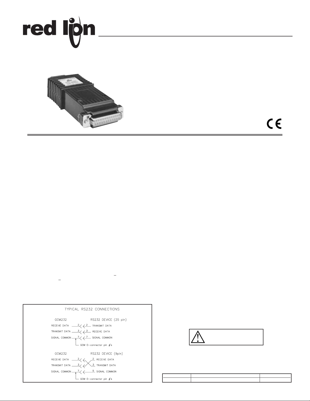
Installation
The power and 20 mA current loop connections should be made with 24
gauge, multi-conductor, shielded cable. Wire insulation should be stripped to
approximately 1/4 inch (stranded wires should be tinned with solder).
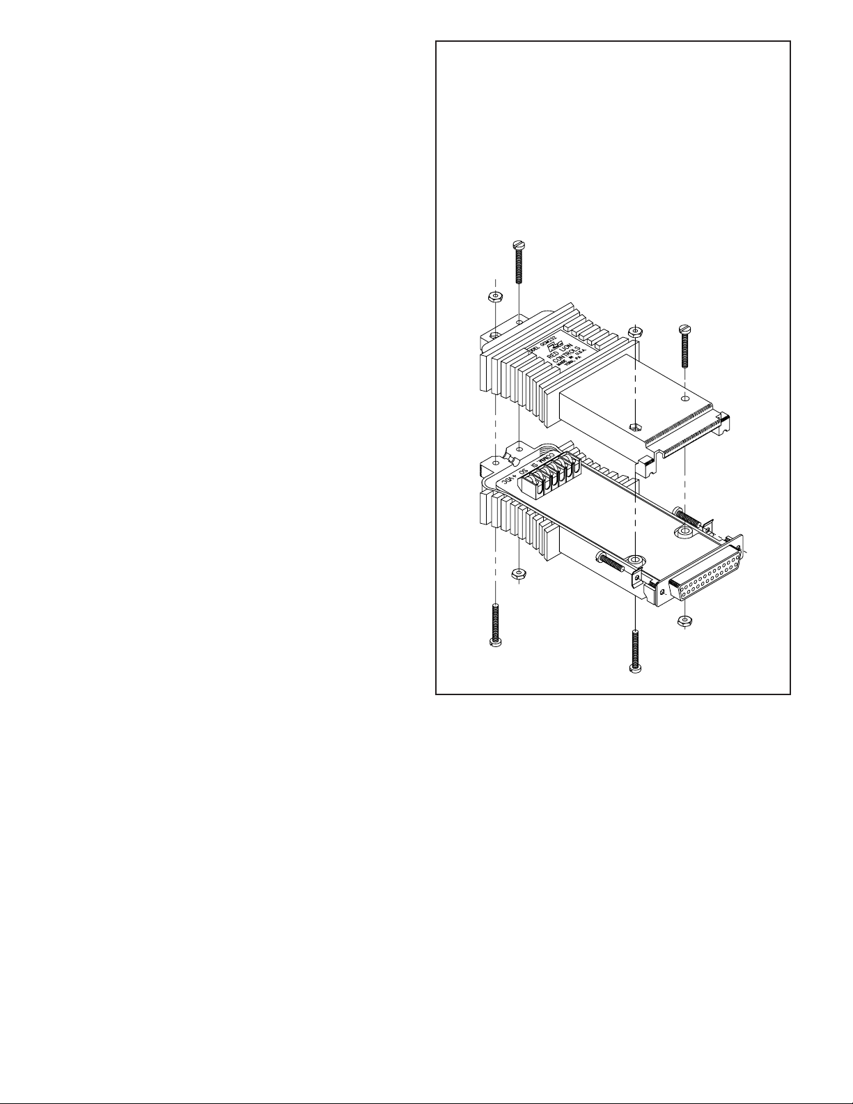
Accessing the terminal block is accomplished by removing the four screws
and nuts that hold the two halves together. Connect the power and 20 mA
loop wires to the appropriate terminal block pins, and route the cable
through the groove at the rear of the module.
Install the two screws and saddle
washers into the slots at the 25-pin
D-connector.
The two halves are placed
together, then secured with the four
screws and nuts. Refer to figure 1
below for assembly.
FIGURE 1
2
Courtesy of Steven Engineering, Inc.-230 Ryan Way, South San Francisco, CA 94080-6370-Main Office: (650) 588-9200-Outside Local Area: (800) 258-9200-www.stevenengineering.com
TYPICAL POWER AND 20 mA LOOP CONNECTIONS
FIGURE 2
TYPICAL CONNECTION FOR MULTIPLE UNITS
FIGURE 3
TROUBLESHOOTING
For further technical assistance, contact technical support at the appropriate
company numbers listed.
3
Courtesy of Steven Engineering, Inc.-230 Ryan Way, South San Francisco, CA 94080-6370-Main Office: (650) 588-9200-Outside Local Area: (800) 258-9200-www.stevenengineering.com
Red Lion Controls
20 Willow Springs Circle
York PA 17402
Tel +1 (717) 767-6511
Fax +1 (717) 764-0839
Red Lion UK Ltd
Tapton Park
Chesterfield S41 OTZ
Tel +44 (1246) 22 21 22
Fax +44 (1246) 22 12 22
Red Lion Controls France
56 Boulevard du Courcerin, Batiment 21,
ZI Pariest F-77183 Croissy Beaubourg
Tel +33 (64) 80 12 12
Fax +33 (64) 80 12 13
Courtesy of Steven Engineering, Inc.-230 Ryan Way, South San Francisco, CA 94080-6370-Main Office: (650) 588-9200-Outside Local Area: (800) 258-9200-www.stevenengineering.com

This manual suits for next models

1

Other red lion Media Converter manuals

red lion PRA2 User manual

red lion

red lion PRA2 User manual

red lion DA10D User manual

red lion

red lion DA10D User manual

red lion DA50D User manual

red lion

red lion DA50D User manual

red lion GCM422 Manual

red lion

red lion GCM422 Manual

red lion IFM User manual

red lion

red lion IFM User manual

red lion GCM232 User manual

red lion

red lion GCM232 User manual

red lion N-Tron 1000 Series Installation instructions

red lion

red lion N-Tron 1000 Series Installation instructions

red lion ICM5 User manual

red lion

red lion ICM5 User manual

red lion ITMA Series User manual

red lion

red lion ITMA Series User manual

red lion N-Tron 1000 Series Installation instructions

red lion

red lion N-Tron 1000 Series Installation instructions

red lion IAMA0001 User manual

red lion

red lion IAMA0001 User manual

red lion IFMA0035 User manual

red lion

red lion IFMA0035 User manual

red lion IAMS0002 User manual

red lion

red lion IAMS0002 User manual

red lion DA30D User manual

red lion

red lion DA30D User manual

Popular Media Converter manuals by other brands

Coby CXCD470 instruction manual

Coby

Coby CXCD470 instruction manual

Panduit Atlona AT-VCC-RS232-KIT installation guide

Panduit

Panduit Atlona AT-VCC-RS232-KIT installation guide

Microchip Technology MCP16251 Reference design

Microchip Technology

Microchip Technology MCP16251 Reference design

Chauvet DJ DMX-AN2 Quick reference guide

Chauvet DJ

Chauvet DJ DMX-AN2 Quick reference guide

Synapse SDI110 user manual

Synapse

Synapse SDI110 user manual

TRENDnet TU-IDES Quick installation guide

TRENDnet

TRENDnet TU-IDES Quick installation guide

ANTIFERENCE HDMI0102SCATV3 user guide

ANTIFERENCE

ANTIFERENCE HDMI0102SCATV3 user guide

BEL LDD240-11024 installation instructions

BEL

BEL LDD240-11024 installation instructions

Mitsubishi Electric AJ65SBT2B-64DA user manual

Mitsubishi Electric

Mitsubishi Electric AJ65SBT2B-64DA user manual

Allied Telesis CONVERTEON AT-CM2K0S datasheet

Allied Telesis

Allied Telesis CONVERTEON AT-CM2K0S datasheet

Transition Networks METTF1011-120 user guide

Transition Networks

Transition Networks METTF1011-120 user guide

M-system 17MS instruction manual

M-system

M-system 17MS instruction manual

Mastervolt MAGIC 12/12-20 user manual

Mastervolt

Mastervolt MAGIC 12/12-20 user manual

Lika Rotacod EM58 MT Series user guide

Lika

Lika Rotacod EM58 MT Series user guide

DVDO iScan VP50PRO owner's manual

DVDO

DVDO iScan VP50PRO owner's manual

Hohner PR90 Series user manual

Hohner

Hohner PR90 Series user manual

Advanced Axis AX AV-V70 Installation, operation, & programming manual

Advanced

Advanced Axis AX AV-V70 Installation, operation, & programming manual

D-Link 1000Base-T to mini-GBIC Media Converter... Quick installation guide

D-Link

D-Link 1000Base-T to mini-GBIC Media Converter... Quick installation guide

manuals.online logo
manuals.online logoBrands
  • About & Mission
  • Contact us
  • Privacy Policy
  • Terms and Conditions

Copyright 2025 Manuals.Online. All Rights Reserved.