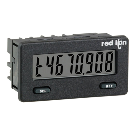
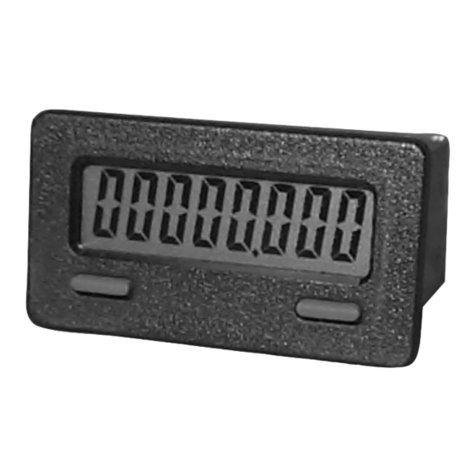
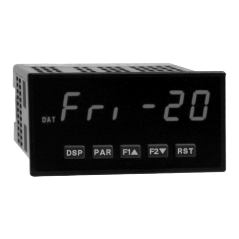
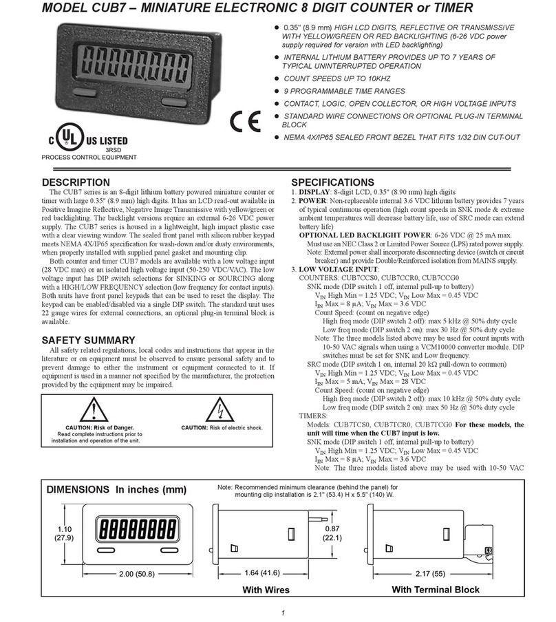
red lion C48T User manual

1
OLCD, 7 SEGMENT, 2 LINE, 6 DIGIT DISPLAY, POSITIVE
REFLECTIVE OR NEGATIVE TRANSMISSIVE MODELS WITH
RED TOP LINE AND GREEN BOTTOM LINE BACKLIGHTING
OSOLID STATE AND RELAY OUTPUT MODELS
OFIELD REPLACEABLE RELAY OUTPUT BOARDS
OSTATUS INDICATORS FOR OUTPUTS
ONEMA 4X/IP65 SEALED FRONT BE EL
OPROGRAMMABLE USER INPUTS AND FRONT PANEL
FUNCTION KEY
OPARAMETER SECURITY VIA PROGRAMMABLE OPERATOR
ACCESS PRIVILEGES AND PROTECTED VALUE MENU
OHORI ONTAL OR VERTICAL STACKING OF MULTIPLE UNITS
O85 to 250 VAC or 18 to 36 VDC/24 VAC POWERED UNITS
ORS485 SERIAL COMMUNICATIONS OPTION
OCHOICE OF NUMERIC DATA ENTRY MODES
DESCRIPTION
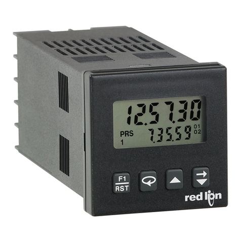
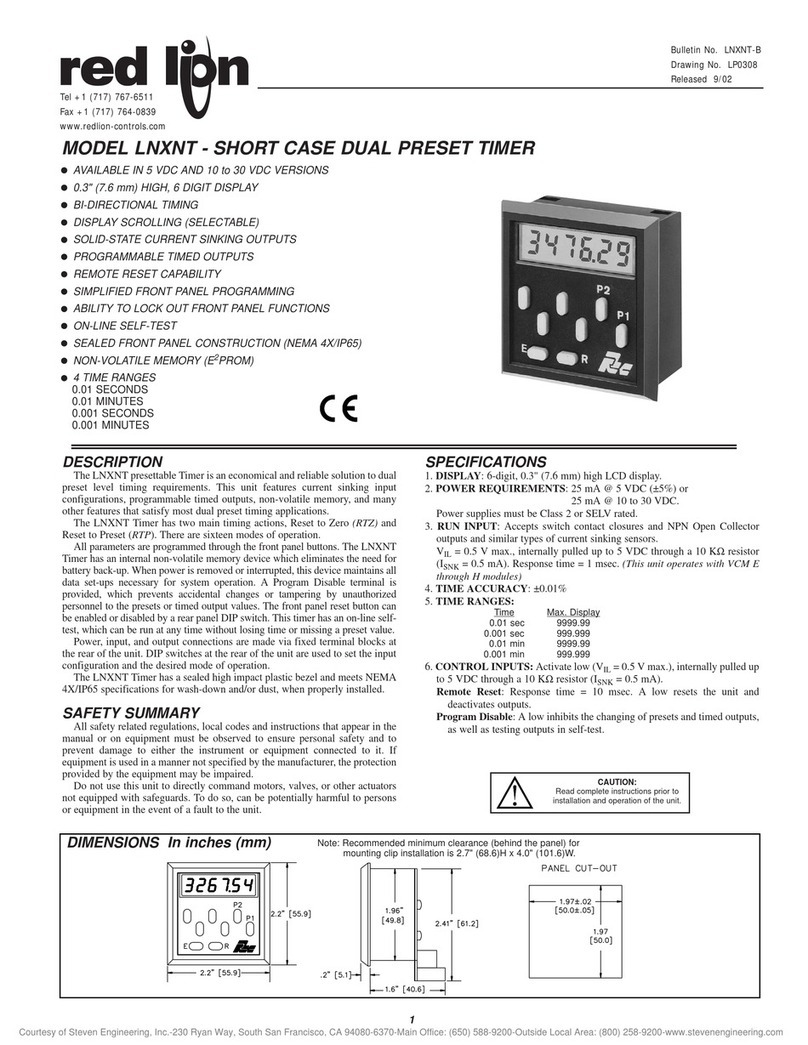
The Model C48 Timer is available in Single or Dual Preset models. The
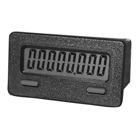
C48T features a 7 segment, 2 line by digit reflective or backlit LCD display.
For the backlit versions, the main display line is red and shows the timer value.
The smaller secondary display line is green, and can be used to view the preset
values or output time values.
The C48 timer can be configured for a variety of different operating modes
to meet most timing application requirements. Twelve timing ranges are
available from thousandths of a second to hours and minutes. Decimal Points
are used to separate the time units (hours, minutes, seconds). Timing can be
cumulative or can reset and start upon each power cycle. “On Delay” or “Off
Delay”, “Single Shot”, “Repetitive auto cycling” modes are all supported.
The Timer can also be configured to Continue or Stop timing upon reaching
Preset. The display can be programmed to stop at the preset value (Reset to Zero
mode) or zero (Reset to Preset mode), or automatically reset to zero or preset
and hold. Once stopped, the timer can be restarted by manually resetting it, or
it can be programmed to restart when power is reapplied.
The C48 Timer has a Run/Stop Input, 3 programmable User Inputs, and a
programmable front panel function key. The Run/Stop and User Inputs can be
configured as sinking (active low) or sourcing (active high) inputs via a single
plug jumper. The user inputs and the front panel function key can be configured
to provide a variety of functions.
Four front panel push-buttons are used for programming the operating modes
and data values, changing the viewed display, and performing user
programmable functions, e.g. reset, etc. The C48T can be configured for one of
two numeric data entry methods, digit entry or automatic scrolling. The digit
entry method allows for the selection and incrementing of digits individually.
The automatic scrolling method allows for the progressive change of one
through all digit positions by pressing and holding the “up” or “down” button.
The Dual Preset models are available with solid-state or Relay outputs. The
Single Preset model has a solid-state and relay output in parallel. All solid-state
outputs are available in a choice of NPN current sinking or PNP current
sourcing, open-collector transistor outputs. All relay output boards are field
replaceable.
The optional RS-485 serial communication interface provides two-way
communication between a C48 and other compatible equipment such as a
printer, PLC, HMI, or a host computer. In multipoint applications (up to thirty-
two), the address number of each C48 on the line can be programmed from 0 to
99. Data from the C48 can be interrogated or changed, and alarm output(s) may
be reset by sending the proper command code via serial communications. PC
software, SFC48, allows for easy configuration of controller parameters. These
settings can be saved to disk for later use or used for multi-controller down
loading. On-line help is provided within the software.
The unit is constructed of a lightweight, high impact plastic case with a
textured front panel and a clear display window. The front panel meets NEMA
4X/IP 5 specifications when properly installed. Multiple units can be stacked
horizontally or vertically. Modern surface-mount technology, extensive testing,
plus high immunity to noise interference makes the C48 Timers extremely
reliable in industrial environments.
SAFETY SUMMARY
All safety related regulations, local codes and instructions that appear in the
manual or on equipment must be observed to ensure personal safety and to
prevent damage to either the instrument or equipment connected to it. If
equipment is used in a manner not specified by the manufacturer, the protection
provided by the equipment may be impaired.
Do not use this unit to directly command motors, valves, or other actuators
not equipped with safeguards. To do so, can be potentially harmful to persons
or equipment in the event of a fault to the unit.
C48T SERIES - 1/16 DIN TIMERS
MODEL C48TS - SINGLE PRESET
MODEL C48TD - DUAL PRESET
DIMENSIONS “In inches (mm ” PANEL CUT-OUT
Bulletin No. C48T-C
Drawing No. LP0394
Revised 3/0
Tel + (7 7) 767-65
Fax + (7 7) 764-0839
www.redlion-controls.com
UL Recognized Component,
File # E137808

2
SPECIFICATIONS
1. DISPLAY: 2 Line by digit LCD display; Positive image reflective or
negative image transmissive with red (top line) and green (bottom line)
backlighting.
Main Display: 0.3" (7. 2 mm) high digits
Secondary Display: 0.2" (5.08 mm) high digits
Annunciators:
Value: PRS, 1, and 2
Output: 01 and 02
2. POWER REQUIREME TS:
AC Versions (C48CXXX0X):
AC Power: 85 to 250 VAC, 50/ 0 Hz, 9 VA max.
DC Power: 11 to 14 VDC @ 150 mA max. (Non PNP output models)
Note: Models with PNP current sourcing outputs must be powered from AC.
DC Versions (C48CXXX1X):
CO TI UOUS:
DC Power: 18 to 3 VDC; 5.5 W max.
AC Power: 24 VAC r10%; 50/ 0 Hz; 7 VA max.
Note: The +10% toler nce r nge on AC input volt ge must be strictly
dhered to. DO NOT EXCEED 26.4 VAC.
PEAK (START-UP CURRE T):
AC or DC Power: 500 mA peak start-up current for 10 msec max.
DC OUT (VSRC I ) - Terminal 10
For units which do not have PNP current sourcing outputs, this terminal
provides a DC output for sensor power (+12 VDC r15%). The
maximum sensor current is 100 mA.
For units with PNP current sourcing outputs, this terminal serves a dual
purpose depending on the application’s PNP output voltage level and
current requirements.
1. The terminal may be used as a +12 VDC output for sensor power.
In this case, the PNP output voltage level will be +12 VDC
(r15%). A maximum of 100 mA is available for the combination
of sensor current and PNP output sourcing current.
2. If a higher PNP output voltage level or additional output sourcing
current is desired, an external DC supply may be connected
between the “DC OUT (VSRC IN)” and “COMM.” terminals. This
supply will determine the PNP output voltage level, and must be
in the range of +13 to +30 VDC.
An external DC supply can also provide the additional output
sourcing current required in applications where two or more PNP
outputs are “ON” simultaneously. However, the maximum current
rating of 100 mA per individual output must not be exceeded,
regardless of external supply capacity.
3. MEMORY: Nonvolatile E2PROM retains all programmable parameters and
timer values.
4. SE SOR POWER: +12 VDC (r15%) @ 100 mA max.
5. I PUTS: Run/Stop, Usr. In1, Usr In2, and Usr. In3.
Configurable as current sinking (active low) or current sourcing (active high)
inputs via a single plug jumper.
Current Sinking (active low): VIL = 1.5 VDC max, 22 K:pull-up to 5
VDC.
Current Sourcing (active high): VIH = 3.5 VDC min., VIN max = 30 VDC;
22 K:pull-down.
Run/Stop Response Time: 250 Psec max.
User Input Response Time: 5 msec max.
. TIME ACCURACY: r0.01%
7. OUTPUTS: (Output type and quantity are model dependent)
Solid-State:
P Open Collector: ISNK = 100 mA max. @ VOL = 1.1 VDC max; VOH
= 30 VDC max.
P P Open Collector: ISRC = 100 mA max.(See note); VOH = 12 VDC
±15% (using internal supply); VOH = 13 to 30 VDC (using external
supply).
Note: The intern l supply of the C48T c n provide tot l of 100 mA for
the combin tion of sensor current nd PNP output sourcing current.
The supply volt ge is +12 VDC (±15%), which will be the PNP output
volt ge level when using only the intern l supply.
If ddition l PNP output sourcing current or higher output volt ge
level is desired, n extern l DC supply m y be connected between the
“DC Out/In” nd “Comm.” termin ls. This supply will determine the
PNP output volt ge level, nd must be in the r nge of +13 to +30 VDC.
An extern l supply c n provide the ddition l output sourcing current
required in pplic tions where two or more outputs re “ON”
simult neously. However, the m ximum r ting of 100 mA per individu l
output must not be exceeded, reg rdless of extern l supply c p city.
Relay: Form A contact, Rating = 5 A @ 250 VAC, 30 VDC (resistive load),
1/10 HP @ 120 VAC (inductive load)
Relay Life Expectancy: 100,000 cycles min. at max. load rating
Programmable Timed Output(s): User selectable output time resolution
0.01 Second Resolution: 0.01 to 99.99 seconds, ± 0.01% + 10 msec max.
0.1 Second Resolution: 0.1 to 999.9 Seconds, ± 0.01% + 100 msec max.
8. RS485 SERIAL COMMU ICATIO S (Optional): Up to 32 units can be
connected.
Baud Rate: Programmable from 1200 to 9 00 baud
Address: Programmable from 0 to 99
Data Format: 10 Bit Frame, 1 start bit, 7 or 8 data bits, 1 or No Parity bit,
and 1 stop bit
Parity: Programmable for Odd (7 data bits), Even (7 data bits), or None (8
data bits)
9. CERTIFICATIO S A D COMPLIA CES:
UL Recognized Component, File #E137808
Recognized to U.S. and Canadian requirements under the Component
Recognition Program of Underwriters Laboratories, Inc.
ELECTROMAG ETIC COMPATIBILITY
Notes:
AC VERSIONS
1. A power line filter, RLC#LFIL0000 or equiv lent, w s inst lled when the
unit w s DC powered.
DC VERSIONS
To insure compli nce with the EMC st nd rds listed bove, do not connect
ny wires from the termin l(s) l beled “COMM.” to the “DC-” supply
termin l (12), when powering the unit from DC supply.
Refer to EMC Inst ll tion Guidelines section of the m nu l for ddition l
inform tion.
10.E VIRO ME TAL CO DITIO S:
Operating Temperature: 0°C to 50°C
Storage Temperature: -40°C to 70°C
Operating and Storage Humidity: 85% max. relative humidity (non-
condensing) from 0°C to 50°C.
Altitude: Up to 2000 meters
11. ELECTRICAL CO ECTIO : Wire clamping screw terminals.
12. CO STRUCTIO : Black plastic case with collar style panel latch. The
panel latch can be installed for horizontal or vertical stacking. Black plastic
textured bezel with clear display viewing window. Unit assembly with circuit
boards can be removed from the case without removing the case from the
panel or disconnecting the wiring. This unit is rated for NEMA 4X/IP 5
indoor use. Installation Category II, Pollution Degree 2.
13. WEIGHT: .0 oz. (170 g)
SINGLE PRESET MODELS
The C48TS offers a choice of twelve timing ranges with eighteen different
operating modes. The unit has a solid-state output that operates in parallel with
a relay output. The solid-state output is available as an NPN or PNP open
collector transistor.
DUAL PRESET MODELS
The C48TD offers a choice of twelve timing ranges with 42 operating modes.
The unit is available with solid-state or relay outputs. The solid-state outputs are
available as NPN or PNP open collector transistors.
Enclosure class AEN 55011RF interference
Emissions to E 50081-2
Level 3; 10 V/mENV50204Simulation of cordless telephone
150 KHz - 80 MHz
Level 3; 10 V/rms EN 1000-4-RF conducted interference
Level 3; 2 Kv power
Level 4; 2 Kv I/OEN 1000-4-4Fast transients (burst)
80 MHz - 1 GHz
Level 3; 10 V/m EN 1000-4-3Electromagnetic RF fields
Level 3; 8 Kv air
Level 2; 4 Kv contactEN 1000-4-2Electrostatic discharge
200 Hz, 50% duty cycle
Immunity to E 50082-2
900 MHz ± 5 MHz
3
Timer Range Modes -
The timer can be configured to operate in one of 12 time ranges. The table
below shows the various ranges available with the time resolution of each
range.
MODE RANGE RESOLUTION
999.999 Seconds 0.001 sec
9999.99 Seconds 0.01 sec
99999.9 Seconds 0.1 sec
999999 Seconds 1 sec
999.999 Minutes 0.001 min
9999.99 Minutes 0.01 min
99999.9 Minutes 0.1 min
9999.59 Minutes.Seconds 1 sec
999.59.0 Minutes.Seconds.0 0.1 sec
99.59.59 Hours.Minutes.Seconds 1 sec
99.59.99 Hours.Minutes.00 0.01 min
999.59.9 Hours.Minutes.0 0.1 min
FRONT PANEL FEATURES
The C48 Timer features a dual line display. In
the normal operating mode (main display), the
timer value is shown on the top line and preset or
output time values are shown on the bottom line.
The Presets or Output time values can be
programmed to be viewable only, viewable and
changeable, or locked (not viewable) from the
main display.
In the normal operating mode, the presets and
output time values are accessible providing that
these values are not programmed for ‘L’ocked.
Values that are accessible (changeable) can be
changed immediately when viewed in the
secondary display.
USER INTERFACE/PROGRAMMING MODES
The operating modes of the C48T are programmed using the front panel
keypad. To enter the programming menu, the key is pushed and held for 2
seconds. Within the programming menu, the key is used to sequence through
the list of programming parameters.
PROGRAMMING MENU
DISPLAY
-
-
PARAMETER DESCRIPTION
Di it or Auto Scrollin Data Entry Mode
Timer Ran e Modes (See Table on followin pa e)
-Timer Operatin Modes (See Table on followin pa e)
-Reset at Power up
-Accessibility of Preset Values
-Preset 1 and 2 Values
-P1 Track P2 (C48TD only)
-Accessibility of Output Time Values
-Output Resolution
-Output 1 and 2 Time Values
-Reverse Output/Relay Lo ic
-Reverse Output Annunciator Lo ic
-Power up Output State
-User Input 1
-User Input 2
-User Input 3
-User F1 Key
-Pro rammin /Protected Parameter Menu Code
-Scroll Display
-Serial Baud Rate and Parity Settin s
-Serial Unit Address
-Abbreviate Serial Mnemonics
-Print Options
-Print and Reset Time Value
-Load Factory Default Settin s
(RS485 option only)
FRONT PANEL EYPAD
- Performs user Programmed Function
- Cycles through secondary displays.
- Enters Programming Mode or Protected Value Menu
when pushed and held for 2 seconds.
- Scrolls through programming displays.
- Enters Data Values.
- Selects next available mode in programming mode.
- Increments digit in Digit Entry mode.
- Increments value in Auto Scrolling entry mode.
- Selects Data Entry mode for displayed data values.
- Selects Digit to right when in Digit Entry mode.
- Decrements value in Auto Scrolling entry mode.
Program Security/Operator Accessible Values
The Program Disable Plug Jumper, Programmable Code Value, User
Input (programmed for Program Disable), and the Accessible value
parameter settings provide various levels of security against unauthorized
programming changes. The accessible value parameters provide individual
access or locking of each value.
Protected Value Menu
The Protected Value Menu allows access to selected presets and timed
output values without having them viewable or changeable from the main
display. To enter the protected menu, the key is pressed and held, and a
programmed code value is entered.

4
Stop Timer at 02, Auto Reset to Zero at 02 End, 01 and 02 TimedAuto Reset to Preset 2 at 02 End, 01 off at 02, 02 Timed -- 3918
Stop Timer at 02, Auto Reset to Preset 2, 01 off at 02, 02 TimedAuto Reset to Preset 2 at 02 End, 01 and 02 Timed -- 3817
Stop Timer at 02, Auto Reset to Preset 2, 01 off at 02, 02 LatchedAuto Reset to Zero at 02 End, 01 off at 02, 02 Timed -- 3716
Stop Timer at 02, Auto Reset to Preset 2, 01 and 02 TimedAuto Reset to Zero at 02 End, 01 and 02 Timed -- 3615
Stop Timer at 02, Auto Reset to Preset 2, 01 Timed, 02 LatchedAuto Reset to Preset 2, 01 off at 02, 02 Timed -- 3514
Stop Timer at 02, Auto Reset to Preset 2, Latched OutputsAuto Reset to Preset 2, 01 and 02 Timed -- 3413
Stop Timer at 02, Auto Reset to Zero, 01 off at 02, 02 TimedAuto Reset to Zero, 01 off at 02, 02 Timed -- 3312
Stop Timer at 02, Auto Reset to Zero, 01 off at 02, 02 LatchedAuto Reset to Zero, 01 and 02 Timed -- 3211
Stop Timer at 02, Auto Reset to Zero, 01 and 02 TimedManual Reset to Preset 2, 01 off at 02, 02 Timed -- 3110
Stop Timer at 02, Auto Reset to Zero, 01 Timed, 02 LatchedManual Reset to Preset 2, 01 off at 02, 02 Latched -- 309
DUAL PRESET OPERATING MODES
Stop Timer at 02, Auto Reset to Zero, Latched OutputsManual Reset to Preset 2, 01 and 02 Timed -- 298
Stop Timer at 02, Auto Reset to Preset 2 at 02 End, 01 off at 02, 02 TimedStop Timer at 02, Manual Reset to Zero, 01 and 02 Timed
Stop Timer at 02, Manual Reset to Preset 2, 01 off at 02, 02 TimedManual Reset to Preset 2, 01 Timed, 02 Latched
--
--
4221
287
Stop Timer at 02, Auto Reset to Preset 2 at 02 End, 01 and 02 TimedStop Timer at 02, Manual Reset to Zero, 01 Timed, 02 Latched
Stop Timer at 02, Manual Reset to Preset 2, 01 off at 02, 02 LatchedManual Reset to Preset 2, Latched Outputs
--
--
4120
276
Stop Timer at 02, Auto Reset to Zero at 02 End, 01 off at 02, 02 TimedStop Timer at 02, Manual Reset to Zero, Latched Outputs
Stop Timer at 02, Manual Reset to Preset 2, 01 and 02 TimedManual Reset to Zero, 01 off at 02, 02 Timed
--
--
4019
265
Stop Timer at 02, Manual Reset to Preset 2, 01 Timed, 02 LatchedManual Reset to Zero, 01 off at 02, 02 Latched --4
Stop Timer at 02, Manual Reset to Preset 2, Latched OutputsManual Reset to Zero, 01 and 02 Timed -- 243
Stop Timer at 02, Manual Reset to Zero, 01 off at 02, 02 TimedManual Reset to Zero, 01 Timed, 02 Latched -- 232
Stop Timer at 02, Manual Reset to Zero, 01 off at 02, 02 LatchedManual Reset to Zero, Latched Outputs -- 221
25
Stop Timer at 01, Auto Reset to Preset at 01 End, Timed Output
Stop Timer at 01, Auto Reset to Zero at 01 End, Timed Output
Stop Timer at 01, Auto Reset to Preset, Timed Output
Stop Timer at 01, Auto Reset to Preset, Latched Output
Stop Timer at 01, Auto Reset to Zero, Timed Output
Stop Timer at 01, Auto Reset to Zero, Latched Output
-18
-17
-16
-15
-14
-13
-12
-
11
-
Stop Timer at 01, Manual Reset to Preset, Timed Output
Stop Timer at 01, Manual Reset to Preset, Latched Output
Stop Timer at 01, Manual Reset to Zero, Timed Output
SINGLE PRESET OPERATING MODES
Stop Timer at 01, Manual Reset to Zero, Latched Output-9
10
Auto Reset to Preset at 01 End, Timed Output-8
Auto Reset to Zero at 01 End, Timed Output-7
Auto Reset to Preset, Timed Output-6
Auto Reset to Zero, Timed Output-5
Manual Reset to Preset, Timed Output-4
Manual Reset to Preset, Latched Output-3
Manual Reset to Zero, Timed Output-2
Manual Reset to Zero, Latched Output-1
Programmable Operating Modes -
These modes determine the operational characteristics of the timer. In the
tables, 01 and 02 refer to Output 1 and Output 2 respectively.
MULTIPLE UNIT STACKING
The C48T is designed for close spacing of multiple units. Units can be
stacked either horizontally or vertically. For vertical stacking, install the panel
latch with the screws to the sides of the unit. For horizontal stacking, the panel
latch screws should be at the top and bottom of the unit. The minimum spacing
from center line to center line of the units is 1.9 " (49.8 mm). This spacing is
the same for vertical or horizontal stacking.
Note: When st cking units, provide dequ te p nel ventil tion to ensure th t the
m ximum oper ting temper ture r nge is not exceeded.
PANEL CUT-OUT SPACING FOR MULTIPLE UNIT STACKING.
HORIZONTAL ARRANGEMENT SHOWN.
PANEL LATCH INSTALLED FOR VERTICAL
UNIT STACKING
PANEL LATCH INSTALLED FOR
HORIZONTAL UNIT STACKING

5
ORDERING INFORMATION
MODEL NO. DESCRIPTION * NPN O.C.
OUTPUT(S)
RELAY
OUTPUT(S) RS485
85 to 250 VAC18-36 VDC/24VAC
1 Preset Timer, Reflective LCD Yes Yes No C48TS003C48TS013
1 Preset Timer, Backlit LCD Yes Yes No C48TS103C48TS113
2 Preset Timer, Reflective LCD No Yes No C48TD002C48TD012
2 Preset Timer, Reflective LCD No Yes Yes C48TD007C48TD017
C48T 2 Preset Timer, Reflective LCD Yes No Yes C48TD005N/A
2 Preset Timer, Backlit LCD No Yes No C48TD102C48TD112
2 Preset Timer, Backlit LCD No Yes Yes C48TD107C48TD117
2 Preset Timer, Backlit LCD Yes No Yes C48TD105N/A
RBC48 RBC48003YesNoNoDual Preset
RBC48001YesNoYesSin le Preset
PART NUMBER
RELAY
OUTPUT(S)
PNP O.C.
OUTPUT
NPN O.C.
OUTPUT
DESCRIPTIONMODEL NO.
RELAY OUTPUT BOARDS
ONE SHOT TIMING CYCLE
Proper wash down mixture for a food processing plant is an important
factor in maintaining the clean environment required. A disinfectant solution
is added to the mixing/holding tank used for the wash down cycle. When the
holding tank is near empty, a level transducer activates the filler pump. A
C48TS is used to turn on the disinfectant solution pump for a preprogrammed
amount of time during the filling process of the holding tank.
When the filler pump starts, a momentary contact closure activates User
Input 1, resetting the C48 Timer. The timer begins the timing cycle since the
run terminal is connected to common. The normally open relay contacts close
at the timer reset signal activating the disinfectant solution pump. When the
programmed preset is reached, timing stops and the relay deactivates, turning
off the pump controlling the disinfectant solution. The C48 Timer’s preset
cycle time may be changed according to the manufacturer’s concentration
level of the disinfectant.
PROGRAMMING
(min & sec)
(yes)
xxxx.xx
(yes)
(no)
(off)
!
xxxx
APPLICATION
PART NUMBERS FOR AVAILABLE
SUPPLY VOLTAGES
ACCESSORIES
MODEL DESCRIPTION PART NUMBER
SFC48 SFC48PC Confi uration Software for Windows 3.x and 95 (3.5"disk) (for RS-485 Models)
* PNP O.C. output(s) versions are available, contact the factory.

!6-DIGIT TIMER ACCUMULATES TIME IN HOURS,
1/10 HOURS, 1/100 HOURS, OR 1/10 MINUTES
!OPERATES FROM EITHER SWITCH CONTACT, OR
10 to 300 V (AC 50/60 Hz or DC) INPUTS
!SELF-POWERED WITH INTERNAL LITHIUM BATTERY FOR UP
TO 7 YEARS OF CONTINUOUS OPERATION
!AVAILABLE IN FRONT PANEL AND REMOTE RESET OR REMOTE
RESET ONLY MODELS
!EASY SNAP-IN MOUNTING IN 1" X 2" (25 mm x 50 mm) PANEL
OPENING
!IDEAL FOR PORTABLE, MOBILE, OR STATIONARY INDUSTRIAL
EQUIPMENT
DESCRIPTION
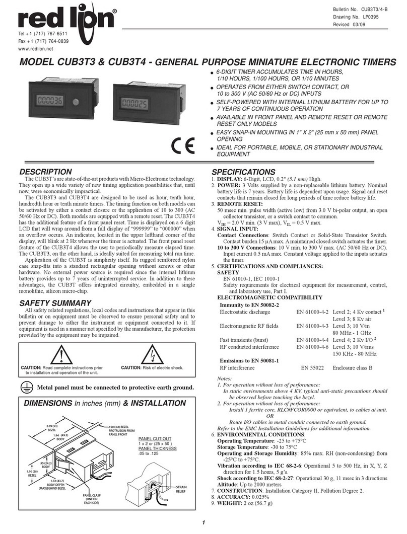
The CUB3T’s are state-of-the-art products with Micro-Electronic
technology. They open up a wide variety of new timing application possibilities
that, until now, were economically impractical.
The CUB3T3 and CUB3T4 are designed to be used as hour, tenth hour,
hundredth hour or tenth minute timers. The timing function on both models can
be activated by either a contact closure or the application of 10 to 300 (AC
50/60 Hz or DC). Both models are equipped with a remote reset. The CUB3T4
has the additional feature of a front panel reset. Time is displayed on a 6 digit
LCD that will wrap around from a full display of “999999” to “000000” when
an overflow occurs. An indicator, located in the upper lefthand corner of the
display, will blink at 2 Hz whenever the timer is actuated. The front panel reset
feature of the CUB3T4 allows the user to periodically measure elapsed time.
The CUB3T3, on the other hand, is ideally suited for measuring total run time.
Application of the CUB3T is simplicity itself. Its rugged reinforced nylon
case snap-fits into a standard rectangular opening without screws or other
hardware. No external power source is required since the internal lithium
battery provides up to 7 years of uninterrupted service. In addition to these
advantages, the CUB3T offers integrated circuitry, embedded in a single
monolithic, silicon micro-chip.
SAFETY SUMMARY
All safety related regulations, local codes and instructions that appear in this
bulletin or on equipment must be observed to ensure personal safety and to
prevent damage to either the instrument or equipment connected to it. If
equipment is used in a manner not specified by the manufacturer, the protection
provided by the equipment may be impaired.
Metal panel must be connected to protective earth ground.
MODEL CUB3T3 & CUB3T4 - GENERAL PURPOSE MINIATURE ELECTRONIC TIMERS
DIMENSIONS “In inches (mm)” & INSTALLATION
SPECIFICATIONS
1. DISPLAY: 6-Digit, LCD, 0.2" (5.1 mm) High.
2. POWER: 3 Volts supplied by a non-replaceable lithium battery. Nominal
battery life is 7 years. Battery life is dependent upon usage. Signal and reset
contacts that remain closed for long periods of time reduce battery life.
3. REMOTE RESET:
50 msec min. pulse width (active low) from 3.0 V bi-polar output, an open
collector transistor, or a switch contact to common.
VIH = 2.0 V min. (3 V max), VIL = 0.5 V max.
4. SIGNAL INPUT:
Contact Connections: Switch Contact or Solid-State Transistor Switch.
Contact burden 15 µamps max. A maintained closed switch will actuate
the timer.
10 to 300 V Connections: 10 V min. to 300 V max. (AC 50/60 Hz or DC).
Input current 0.5 mA max. Constant voltage applied to the inputs will
actuate the timer.
5. CERTIFICATIONS AND COMPLIANCES:
SAFETY
EN 61010-1, IEC 1010-1
Safety requirements for electrical equipment for measurement, control,
and laboratory use, Part I.
ELECTROMAGNETIC COMPATIBILITY
Notes:
1. For operation without loss of performance:
In static environments above 4 KV, typical anti-static precautions should
be observed before touching the bezel.
2. For operation without loss of performance:
Install 1 ferrite core, RLC#FCOR0000 or equivalent, to cables at unit.
OR
Route I/O cables in metal conduit connected to earth ground.
Refer to the EMC Installation Guidelines for additional information.
6. ENVIRONMENTAL CONDITIONS:
Operating Temperature: -25 to +75°C
Storage Temperature: -30 to 75°C
Operating and Storage Humidity: 85% max. RH (non-condensing) from -
25°C to +75°C.
Altitude: Up to 2000 meters
7. CONSTRUCTION: Installation Category II, Pollution Degree 2.
8. ACCURACY: 0.025%
9. WEIGHT: 2 oz (56.7 g)
CAUTION: Read complete instructions prior
to installation and operation of the unit. CAUTION: Risk of electric shock.
PANEL CUT-OUT
1” x 2” or 25 mm x 50 mm
PANEL THICKNESS
.05” to .125”
Bulletin No. CUB3T3/4-A
Drawing No. LP0395
Revised 9/00
Tel +1 (717) 767-6511
Fax +1 (717) 764-6587
www.redlion-controls.com
Immunity to EN 50082-2
Electrostatic discharge EN 61000-4-2 Level 2; 4 Kv contact 1
Level 3; 8 Kv air
Electromagnetic RF fields EN 61000-4-3 Level 3; 10 V/m
80 MHz - 1 GHz
Fast transients (burst) EN 61000-4-4 Level 4; 2 Kv I/O 2
RF conducted interference EN 61000-4-6 Level 3; 10 V/rms
150 KHz - 80 MHz
Emissions to EN 50081-1
RF interference EN 55022 Enclosure class B
Other manuals for C48T
2
This manual suits for next models
3
Table of contents
Other red lion Timer manuals

red lion
red lion LD User manual

red lion
red lion CUB7T1 User manual

red lion
red lion CUB7T User manual

red lion
red lion PAX-1/8 User manual

red lion
red lion C48T User manual

red lion
red lion LD User manual

red lion
red lion PAXTM User manual

red lion
red lion C48T User manual

red lion
red lion CUB7 Series User manual

red lion
red lion PAXCK User manual