Red Sound Micro Sync Beat Xtractor User manual

Issue 3
micro sync
beat xtractor
MIDI OUT
13 8413 84
MIDI CLOCK
BEAT 1
RESET
STOP
OKPULL PUSH
SYNC
bpm
TAP
NUDGE
PULL
BPM
UP
BPM
down
PUSH
POWER
www.redsound.com
INPUT
Red
Sound
the colour of music
micro sync
/
+/
-/


INTRODUCTION
The MICRO SYNC automatically synchronises audio and MIDI in a low-cost package with key
features to further simplify and enhance performance.
With straight-forward connections and setup, a compact case and three mounting options, the
MICRO SYNC will integrate perfectly into any DJ/studio setup.
Please read the following sections of this manual carefully to fully understand the operation of
your new RED Sound MICRO SYNC Beat Xtractor.
Congratulations! By purchasing the MICRO SYNC you have joined an exclusive new club of
re-mixers and Djs who have discovered the future of DJ’ing, mixing MIDI instruments with
audio playback. Previously, to make MIDI happen in time with music was a matter of
painstaking and time-consuming tweaking of MIDI tempos and sound source pitch controls to
keep them even remotely synchronised.
At the heart of the MICRO SYNC is Red
Sound's highly acclaimed ‘V2’ BPM Analysis Engine (taken from the groundbreaking
FEDERATION BPM FX module), which shoulders the responsibility of calculating the tempo of
the music. This leaves you free to concentrate on mixing and adjusting the real-time controls
on your MIDI sequencer/tone module.
CONTENTS
Contents & Introduction ..........................................................................
Front Panel & Connectors .......................................................................
Mounting & Connections .........................................................................
External MIDI Sequencer Settings ..........................................................
OPERATION
Getting Started ............................................................................
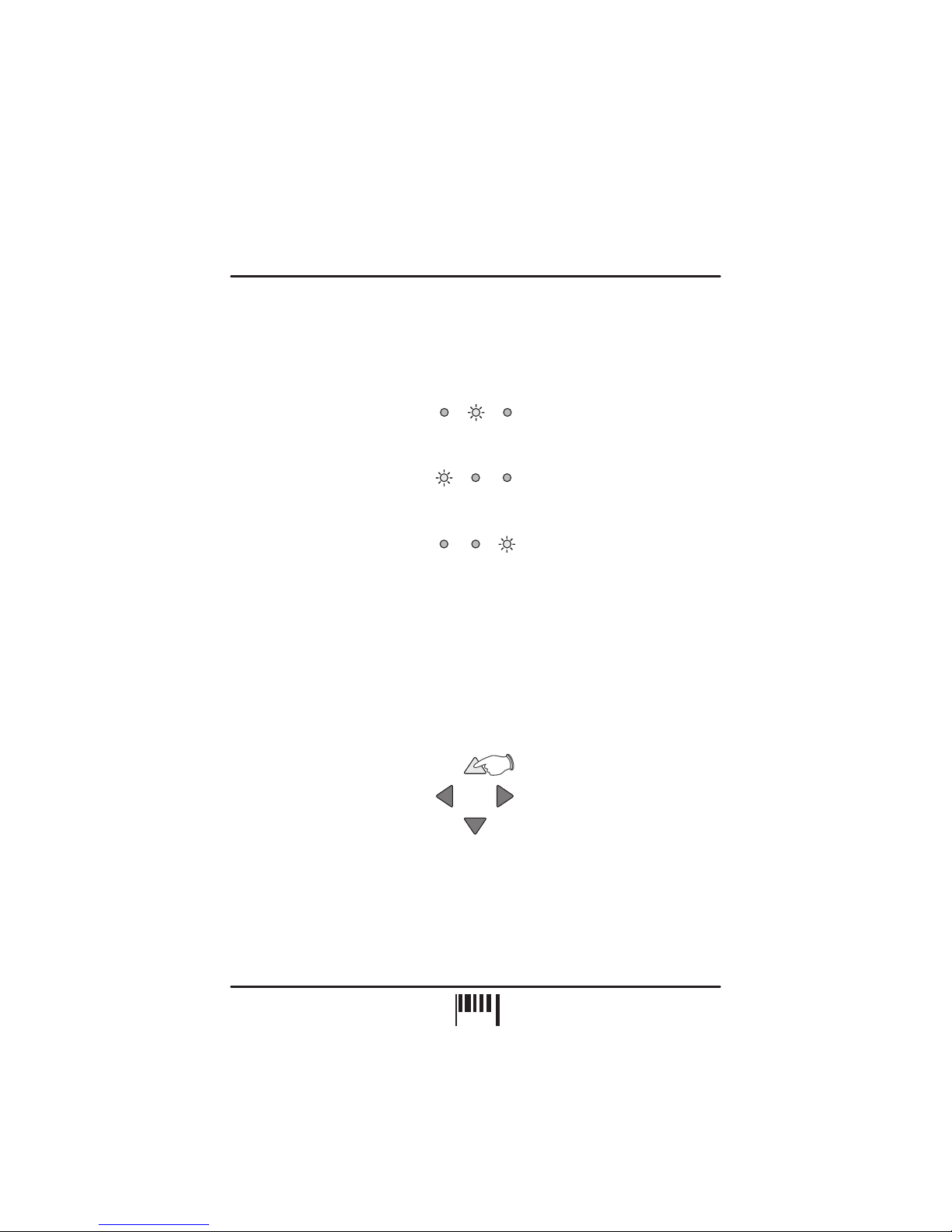
Setting the Correct Input Level ..................................................
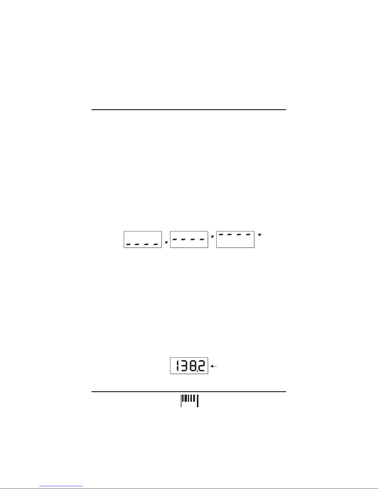
BPM Display ................................................................................
Run/Pause ...................................................................................
Tap (Reset/Stop) .........................................................................
Sync Indicator .............................................................................
Nudge Control ............................................................................
BPM Range. ................................................................................
Specification .......................................................Hints & Tips /
1
2
3
4
4
5
5
6
7
7
8
11
12
OPERATING CRITERIA
This product has been designed to operate most effectively with dance music - i.e. music
based on strong regular beats and patterns. However, as the range of pre-recorded dance
material is virtually limitless (and the audio mix of individual tracks unknown) we cannot
guarantee the performance of the MICRO SYNC with every dance track.
The MICRO SYNC may operate unsatisfactorily if the beat information is either unavailable or
indefinable within the audio track. Please note this when selecting your audio material.
CONTENTS / INTRODUCTION
1
PAGE

MIDI OUT
13 8413 84
MIDI CLOCK
BEAT 1
RESET
STOP
OKPULL PUSH
SYNC
bpm
TAP
NUDGE
PULL
BPM
UP
BPM
down
PUSH
POWER
www.redsound.com
INPUT
Red
Sound
the colour of music
micro sync
/
+/
-/
FRONT PANEL/CONNECTORS
1
2
3
Use the input cable ( to connect
booth/record or master output on
your mixing desk.
Use this bi-colour red/green LED to maintain the
ideal input level. See ‘ Input
Level ’on page 5.
Connect the output plug of the AC adaptor
supplied with the MICRO SYNC to this socket.
AUDIO INPUT - Connector
POWER IN - Connector
supplied) this
socket to the
Setting the correct
The four digit BPM reading of the audio signal will
be displayed here.
Press this button to run or pause the connected
MIDI sequencer. (Also sets the BPM range)
Tap this button to manually enter a BPM. Press
and hold the button to stop the MIDI clock and
reset the BPM display.
This 3-way indicator shows any synchronisation
adjustments.
Use this 4-way keypad to manually edit the BPM
reading or adjust the audio/MIDI sync point - see
page 8. (Also used for parameter editing)
This 8 indicator display ‘rotates’ at the BPM rate
when the MICRO SYNC’s MIDI clock is running.
Use a suitable MIDI cable to connect this socket to
the MIDI IN connector on your sequencer.
AUDIO INPUT LEVEL - Indicator
BPM - Display
RUN/PAUSE - Button
TAP (RESET/STOP) - Button
SYNCHRONISATION - Display
NUDGE - 4 Buttons
MIDI CLOCK - Display
MIDI OUT - Connector
4
5
6
7
8
9
10
FRONT PANEL CONTROLS AND
CONNECTORS
Here’s a quick guide to the controls and connectors
on the MICRO SYNC.
3
1
10
2
5
9
7
8
6
4
2
PAGE

CONNECTING THE
MICRO SYNC TO YOUR
SYSTEM
When you have chosen the best
mounting option for your system setup,
connect the MICRO SYNC as follows:
1. Using the input cable ,
connect the 3.5mm plug end to the
socket marked ‘INPUT’ on
the panel.
2. Connect the RCA phono plugs of the
cable to a suitable line level output on
your mixing desk. (Record, Booth etc.)
3.
Connect the MIDI OUT socket on the
front panel of the MICRO SYNC to the
MIDI IN socket of your sequencer, using
a suitable MIDI cable.
supplied
MICRO SYNC
rear
Connect the output plug of the AC
power adaptor to the MICRO SYNC’s
power in socket on the rear panel.
4.
You can choose one of three mounting options
included with the MICRO SYNC.
1. - Stick one in each corner on
the underside panel for free mounting.
2. - Stick one
either side of the serial number label on the
underside panel. Locate a flat, clean surface
on your equipment/rig, peel-off film and press
firmly into place for a permanent mounting.
3.
- The MICRO SYNC
can be conveniently located on either side of a
mixing desk for a semi-permanent mounting.
Rubber feet
Double sided adhesive pads
Brackets, for use with 19” rack mount
holes on mixing desks
MOUNTING THE MICRO SYNC
MOUNTING/CONNECTIONS
INPUT CABLE
(SUPPLIED) TO AC
ADAPTOR
19” RACK
Hole pitch
range =
Min 90mm
Max 240mm
Rotate the chrome
brackets to line-up
with the 19” rack
mounting holes on
your mixing desk.
M3 SCREW
(LENGTH = 6mm MAX)
BRACKET
M6 SCREW
M6 NUT
DJ MIXING DESK PANEL
19” RACK MOUNT HOLE
MIXING DESK
MIDI OUT
RED
MICRO SYNC
Beat Xtractor
MIDI CLOCK
BEAT 1
TAP
/
(RESET
/STOP)
OKPULL PUSH
SYNC
RL
MIDI IN
SUITABLE
MIDI CABLE
TO SUB-MIXER: DO NOT
CONNECT MIDI AUDIO
SIGNAL BACK INTO MAIN
MIXER AS A FEED-BACK
LOOP WILL OCCUR.
MIDI SEQUENCER / TONE MODULE
AUDIO OUT
RECORD/BOOTH
OR
MASTER OUTPUT
303/505
NUDGE
PULL
BPM
-/DOWN
BPM
+/UP
PUSH
3
PAGE

EXTERNAL MIDI SEQUENCER SETTINGS
QUASIMIDI RAVE-O-LUTION 309
In the 'EDIT' page press F3 to select 'SYSTEM'. Select page 3 with the 'PAGE' dial. Use the
'EDIT VALUE' wheel to set MIDI SYNC to 'EXT'.
GETTING STARTED/POWERING UP
When power is first applied to the MICRO SYNC the software version fitted to your unit will be
shown in the main display.
Afterwards, the four centre bars will light to indicate the BPM engine is currently ‘IDLE’.
Before the MICRO SYNC can operate correctly your MIDI sequencer must first be set to
recognise e MIDI Clock commands. Please consult the manufacturers operation
manual to make the necessary settings. Here are some typical examples:
In System Settings, set the 'SYNCHRONIZATION SETTING' to 'Slave' mode.
In Master Menu, set 'GLOBAL TEMPO' down below 1 BPM to 'External' mode and set the
'BEATS MODE to 1, 2 or 3.
xternal
ROLAND MC-303/505
E-MU Orbit / Planet Phatt etc.
The MICRO SYNC has been designed to operate from the main output signal on a mixing
desk or any line level audio source. When connecting to a mixing desk, this signal can usually
be taken from a secondary parallel master output labelled ‘RECORD’ or ‘BOOTH OUTPUT’. If
your mixing desk does not feature this type of output, use two ’Y’ type RCA phono splitter
connectors on the master output terminals so that both the amplification system and MICRO
SYNC receive the same signal. Alternatively you can connect to any ‘EFFECT SEND’.
NOTE 1: When the MICRO SYNC is in use, avoid changing any volume or tone controls on
the mixing desk as this could greatly affect the MICRO SYNC's synchronisation performance.
(Example: a ‘Bass’ tone control turned right down would eliminate all the kick drum beat
information from the track).
NOTE 2: A sub-mixer MUST be used to combine the MIDI driven audio and main audio
output signals - see connection diagram. MIDI driven audio played back into the MICRO
SYNC’s input from the main mixer will create a feedback loop. This will result in the MICRO
SYNC following it's own tempo rather than the master audio signal.
BPM
BPM
Software version = 2.02
(i.e. ‘V2’ BPM engine)
Four static centre bars
indicate ‘IDLE’ condition
(no audio beat detected)
OPERATION
PAGE
4

4 rising
centre bars
indicate
'input over-
load' condition
BPM BPM BPM
SETTING THE CORRECT INPUT LEVEL
BPM DISPLAY
The MICRO SYNC’s input stage will work most effectively when the audio levels within your
mixing desk are set to their nominal settings i.e. Individual channel Gain/level controls set to
0dB - Master output fader set to 0dB. The bi-colour ‘INPUT’ indicator at the top of the front
panel can show four different input level conditions as follows:
OFF - No audio signal present
DIM GREEN - Audio signal present - Level too low
BRIGHT GREEN - Audio signal present -
RED - Overloaded signal - Level too high
For satisfactory operation, this indicator should always be BRIGHT GREEN, occasionally
flashing RED. If the indicator shows a different condition, check the channel/master settings
on your mixing desk.
If the signal level is continuously too high, a secondary overload warning will be shown on the
main display as follows:
If the display shows the overload warning at any time, check and adjust back the gain settings
on the mixing desk.
Play a track containing steady, definable beat information on any connected sound source,
route it to the master output on your mixing desk and set the master level fader to it’s normal
operating position. If the MICRO SYNC is connected to the ‘Booth’ outputs on your mixing
desk, turn up the Booth Output level control until the ‘Input’ indicator lights BRIGHT GREEN,
occasionally flashing RED. If the MICRO SYNC is connected directly to the master outputs,
turn up the Master fader until the Input indicator shows the same condition as above.
The main display should now show the BPM reading of the master audio signal as in the
following example:
Ideal working level
IMPORTANT NOTE: If the indicator is continuously DIM GREEN, the BPM engine may
operate erratically. If the indicator is continuously RED the BPM engine may cease to function.
NOTE: Regularly check and adjust the input level setting to compensate for individual track
level variations.
BPM
Example reading = 138.2 BPM
OPERATION
PAGE
5

Also, the indicator and ‘Beat 1’ indicator in the MIDI CLOCK display will flash at the
detected BPM rate to show ‘PAUSE’ mode. The right-hand digit of the BPM display may
fluctuate slightly as the BPM engine constantly analyses and updates the reading in real-time.
Any progressive shift in tempo (slowly changing the playback speed using a CD/vinyl deck’s
pitch control) should be tracked and displayed by the MICRO SYNC.
IMPORTANT NOTE: If the BPM engine has picked up on the OFF-BEAT information in the
track (LEDs flashing on the off-beats) from a prominent Hi-Hat etc., you can use the NUDGE
control’s Pull/Push feature to adjust the synchronisation to the on-beat position - see page 8.
RUN/PAUSE Button ( )
Select a suitable pattern on your MIDI sequencer (basic percussion parts are best when
starting out).
To run the MIDI sequencer, press the 'RUN/PAUSE' button once.
The RUN/PAUSE indicator will now stay on and the MIDI CLOCK display will 'rotate' in
synchronisation with the audio BPM rate to indicate that the MIDI clock output is active. The
selected pattern in your MIDI sequencer should now be playing in synchronisation with the
audio track.
To pause the MIDI sequencer at any time, press the 'RUN/PAUSE' button again. The
MIDI CLOCK display will stop rotating and the RUN/PAUSE / Beat 1 indicators will flash to
indicate PAUSE mode. The MIDI sequencer's pattern or song will be held at the pause
position and will only continue from that point when the RUN/PAUSE button is next pressed.
If you want to run the MIDI pattern from the start point again, in pause mode press the
TAP button before pressing the RUN/PAUSE button again. This resets the MIDI pattern
or song to beat 1/bar1.
If the strong regular beats in the audio track become unavailable at any time, the 3 remaining
decimal point indicators in the main display will flash continuously as shown:
RUN:
PAUSE:
RESET:
NOTE: To set the initial alignment of the MIDI sequence and audio track, press this button
accurately on the desired beat. Any misalignment error at this stage will be automatically
corrected during the first few seconds of operation. This feature allows you to choose the
exact start point of the MIDI pattern.
once
IMPORTANT NOTE: The MICRO SYNC will continue running the MIDI clock output indefinitely
at the last detected BPM rate if the strong regular beats in the audio track become
unavailable. This feature allows the connected MIDI sequencer to fill in parts during quite
passages in the audio track without interruption or to continue playing after the track has
finished.
/
/
3 flashing decimal points indicate
'free-wheeling' condition
BPM
OPERATION
PAGE
6

This will occur approximately 3-4 seconds after the last valid BPM reading was taken to warn
that the MICRO SYNC is now 'free-wheeling' and the BPM display is no longer being updated
from the audio track. When the strong regular beats in the audio track return the MICRO
SYNC will automatically detect the BPM information and make any necessary adjustments, at
which time the flashing decimal point indicators will go out to indicate a 'locked-in' condition.
This multi-function button allows you to manually enter a tempo (TAP), reset the MIDI pattern
to beat1/bar1 (RESET) in pause mode, dis-engage the automatic beat synchronisation or stop
the MIDI device (STOP).
The TAP feature can be used to set the MIDI Clock speed when there is no audio signal
present or when the beat information becomes unavailable during a quite passage of the
audio track (intro, middle eight etc.).
To enter a BPM rate from IDLE (no audio beat detected) use your finger to tap in a tempo on
the TAP button. After 3-4 taps the tempo will be shown on the main BPM display. The
RUN/PAUSE and Beat 1 indicators will flash at the BPM rate to show PAUSE mode.
The TAP feature can also be used to override the BPM engine whilst detecting a BPM or 'free-
wheeling’. Use your finger to tap in the tempo. After 3-4 taps the new tempo will be shown on
the main BPM display and the MIDI clock will immediately change to run at the new rate.
For details on the RESET function please see previous page.
The TAP button can also be used to temporarily disengage the
MICRO SYNC’s automatic beat tracking whilst in RUN mode. This feature allows the MICRO
SYNC to ignore sections of erratic, offbeat material present in certain sections of many audio
tracks that can cause unnecessary adjustments and temporary disruption to the
synchronisation. The MIDI device can then run- on, uninterrupted at the last detected
synchronisation setting.
In RUN mode only, press the TAP button. The three indicators in the SYNC display (and the
decimal points in the main display) will flash together at the BPM rate to indicate ‘Sync
Disengaged’ mode. To reset the automatic tracking back ON, press the TAP button again. The
indicators in the SYNC and MAIN displays will revert to their normal operation.
The STOP function is used to stop the MIDI Clock and clear BPM readings from the
MICRO SYNC. Press and the TAP(RESET/STOP) button for approximately 1
second. The BPM reading in the main display will be replaced by four centre bars and the
MIDI CLOCK, RUN/PAUSE indicators will go out (and the connected MIDI device will stop).
TAP Button(RESET/STOP)
TAP:
RESET TO BEAT 1/BAR 1:
DISENGAGE AUTO- SYNC:
STOP:
NOTE: Subsequent valid beat information detected by the BPM engine may override any
manual changes made with the TAP function.
hold down
OPERATION
PAGE
7

SYNC Indicator
NUDGE Control
This 3-way indicator shows beat synchronisation adjustments between the audio track and
the MIDI sequencer’s beat position. The MICRO SYNC constantly analyses the accuracy of
the relative beat positions and will either 'PULL' or 'PUSH' the MIDI clock output to maintain
this synchronisation.
When the audio and MIDI are the green 'OK' indicator will light.
If the MIDI clock is of the audio, the red 'PULL' indicator will light.
If the MIDI clock is the audio, the red 'PUSH' indicator will light.
The 4-button NUDGE control lets you make fine adjustments to the BPM rate and audio/MIDI
synchronisation point.
During normal operation,
the BPM engine will automatically detect and adjust itself to the correct BPM value. However,
if the MICRO SYNC’s software is ‘free-wheeling’ or you wish to adjust a ‘tapped in’ tempo, you
can use the North /South positions of the NUDGE control to increase or decrease the BPM
value in 0.1 BPM steps.
To increase the BPM reading by 0.1 BPM, press the top button once, as in the following
example:
To decrease the BPM reading, press the lower button once ( ). Press and hold down
either button to scroll through the BPM values. Further ‘valid’ beat information detected by the
BPM engine will override any manual changes made with these buttons.
The BPM +/Up, -/Down buttons can be used to quickly enter a
default BPM value. When the BPM engine is ‘Idle’ (four centre bars on), simply press either
button to set the default reading of 120 BPM . The MICRO SYNC is now ready to run the
connected MIDI sequencer at 120 BPM. You can adjust this setting with the TAP or NUDGE (-
/BPM or +/BPM) buttons.
synchronised
ahead
behind
BPM Adjustments (using BPM +/Up and BPM -/Down buttons):
Setting the default BPM -
BPM -/DOWN
NUDGE
PULL
BPM
-/DOWN
BPM
+/UP
PUSH
OKPULL PUSH
SYNC
OKPULL PUSH
SYNC
OKPULL PUSH
SYNC
OPERATION
PAGE
8

SYNC Adjustments (using PULL and PUSH buttons):
PULL THE SYNCHRONISATION:
Under normal circumstances the
BPM engine will automatically detect and adjust the audio/MIDI trigger point to either the on-
beat or off-beat position depending on whichever is more prominent in the audio track. You
can use the PUSH/PULL feature to make fine adjustments to the synchronisation (if the MIDI
sequencer sounds slightly ahead or behind the beat of the audio) or complete ½ beat steps (if
the BPM engine has locked to the off-beat when you require synchronisation to be on the beat
or vic-versa).
To check the current trigger synchronisation setting, press either the ‘PULL’ or PUSH’ button
once. The main BPM display and SYNC indicators will now show the current setting, as in the
following example:
After 4 seconds the BPM display and SYNC indicators will revert to their normal operation.
To adjust the trigger synchronisation setting, again press one of the buttons marked ‘PULL’ or
‘PUSH’ and then, during the 4 second display period, press either button again to change the
setting. Each half beat measure has 12 interim settings which allow very fine adjustments to
be made to the synchronisation.
To ‘Pull’ the MIDI clock backwards, press the left button
(PULL) during the 4 second display period.
The display reading will change for each press as follows:
After the ‘-11’ setting, the synchronisation will be pulled back exactly ½ beat, as indicated by
the following display:
NUDGE
PULL
BPM
-/DOWN
BPM
+/UP
PUSH
BPM
LGH / BAR POS
BPM BPM
LGH/BAR LGH/BARPOS POS
OK OK OKPULL PULL PULLPUSH PUSH PUSH
Etc. to -11
BPM
Example: Trigger point =
‘Synchronised’
Flashing ‘OK’ indicator
SYNC
OKPULL PUSH
OPERATION
PAGE
9

Further fine adjustments can be made beyond the ‘PULL ½ beat’ point (display reads from
‘-13’ down to ‘-23’) until the synchronisation is pulled back by one complete beat (maximum
PULL adjustment). For this setting the display will show the following:
To ‘Push’ the MIDI clock forwards, press the right button
(PUSH) during the 4 second display period.
The display reading will change for each press as follows:
NOTE: You can adjust the PULL/PUSH setting in complete ½ beat steps by pressing and
holding down either button for 1 second.
PUSH THE SYNCHRONISATION:
NUDGE
PULL
BPM
-/DOWN
BPM
+/UP
PUSH
BPM
LGH / BAR POS
OK OK OKPULL PULL PULLPUSH PUSH PUSH
Etc. to +11
BPM BPM
LGH/BAR LGH/BARPOS POS
BPMBPM
OKOK PULLPULL PUSHPUSH
Display alternates
between
LGH / BAR POS LGH / BAR POS
BPMBPM
OKOK PULLPULL PUSHPUSH
Display alternates
between
LGH/BAR LGH/BARPOS POS
BPMBPM
OKOK PULLPULL PUSHPUSH
Display alternates
between
LGH/BAR LGH/BARPOS POS
After the ‘+11’ setting, the synchronisation will be pushed forwards exactly ½ beat, as indicated
by the following display:
OPERATION
10
PAGE

BPMBPM
OKOK PULLPULL PUSHPUSH
Display alternates
between
LGH / BAR POS LGH / BAR POS
Further fine adjustments can be made beyond the ‘PUSH ½ beat’ point (display reads from
‘+13’ up to ‘+23’) until the synchronisation is pushed forwards by one complete beat
(maximum PUSH adjustment). For this setting the display will show the following:
BPM RANGE
This is where you set the working range of the MICRO SYNC’s BPM engine. There are three
operating bands, each specifically designed to complement different styles of music from slow
ballads to the fastest ‘Speed Garage’. This setting can only be accessed when the BPM
engine is in the ‘Idle’ condition (four centre bars). To check the setting in idle mode, press
the button once, the display will alternate between:
SETTING RANGE = LOW (60 to 120BPM), MED (90 to 180BPM), HIGH (115 to 230BPM)
To change the BPM range, use the NUDGE control ‘BPM +/UP’ or ‘BPM -/DOWN’ buttons, as
in the following example:
To exit ‘BPM edit’ mode, simply press the button again. The MICRO SYNC will now
return to ‘Idle’ mode.
NOTE 1: BPM’s outside of the selected range limit cannot be analysed. Always check the
general tempo of the music you are playing falls well within the selected BPM range. For most
applications we recommend the MID BPM range of 90-180BPM.
NOTE 2: This setting is not memorised. Each time the MICRO SYNC’s power is turned on, the
default setting (90-180 BPM) will be restored.
‘r’ = range
BPM
BPM
BPM
BPM
Display alternates
between
Display alternates
between
Default setting = MED(90-180 BPM)
New setting = HI (115-230 BPM)
LGH/BAR
LGH/BAR
LGH/BAR
LGH/BAR
POS
POS
POS
POS
NUDGE
PULL
BPM
-/DOWN
BPM
+/UP
PUSH
/
/
OPERATION
11
PAGE

* Specification and /or appearance subject to change without prior notice due to product
improvement.
Patent Pending
SPECIFICATION
BPM Engine
BPM Range
Lock-in time
Accuracy
Input Level
Displays
BPM
Sync
Input
MIDI Implementation
Power Supply
Dimensions/Weight
3 x ranges: Low = 60 to 120 BPM, Med = 90 to 180 BPM,
High = 115 to 230 BPM
Typically2-4sec's(from introduction of readable beat information)
0.1 BPM
Nominal line level (1V peak)
1 x 4 character 7 Segment LED
3 x LED
1 x Bi-colour green/red LED
9vDC, 250mA (RED PSU - TYPE A)
42(W)x195(D)x22(H)mm, Less than 0.5 Kg
MIDI clock
Accessories (included)
Input cable
Mounting kit
8 x red LED
1M (3.5mm mini-jack to RCA phono plugs),
2 x chrome brackets/2xM6screws/2xM6nuts/2xM3screws,
2 x double-sided adhesive pads,
4 x rubber feet
System real time / Clock commands = transmitted
HINTS&TIPS / SPECIFICATION
HINTS & TIPS
Tempo Changes:
Synchronisation:
1. Always make slow changes when adjusting the sound source pitch control. This will allow
the MIDI clock to remain in synchronisation during tempo changes.
2. Never make tempo changes during quite passages (when beat information is unavailable)
as the MICRO SYNC will lose synchronisation.
1. Use the NUDGE feature to manually adjust any synchronisation errors during quite
passages (when beat information is unavailable).
2. Get to know a track before a performance to identify passages which upset the
synchronisation. Then disengage the auto SYNC prior to breaks which contain the erratic beat
information.
12
PAGE

FEDERAL COMMUNICATIONS COMMISSION
RADIO FREQUENCY INTERFERENCE STATEMENT
CLASS B NOTICE
CLASSE B AVIS
This equipment has been tested and found to comply with the limits listed for a Class B digital
device, pursuant to Part 15 of the FCC Rules. These limits are designed to provide reasonable
protection against harmful interference in a residential installation. This equipment generates,
uses, and can radiate radio frequency energy and, if not installed and used in accordance with
the instructions, may cause harmful interference to radio communications. However, there is
no guarantee that interference will not occur in a particular installation. If this equipment does
cause harmful interference to radio or television reception, which can be determined by turning
the equipment off and on, the user is encouraged to try to correct the interference by one or
more of the following measures:
- Reorient or relocate the receiving antenna.
- Increase the separation between the equipment and receiver.
- Connect the equipment into an outlet on a circuit different from that to which the receiver is
connected.
- Consult the dealer or an experienced radio/TV technician for help.
Unauthorized changes or modifications to this system can void the users authority to operate
this equipment.
This equipment requires shielded interface cables in order to meet FCC class B limit.
This product complies with the requirements of European Directive 89/336/EEC
This digital apparatus does not exceed the Class B limits for radio noise emissions set out in
the Radio Interference Regulations of the Canadian Department of Communications.
Cet appareil numerique ne depasse pas les limites de la Classe B au niveau des emissions de
bruits radioelectriques fixes dans le Reglement des signaux parasites par le ministere
Canadien des Communications.
For the USA
For Europe
For Canada
Printed in England
Copyright / Software Copyright / Design Right RED Sound Systems Ltd 2001

Bourne House, Cores End Road,
Bourne End, Bucks. SL8 5AR. England
Phone : +44 (0)1628 819191
Fax : +44 (0)1628 819111
Table of contents
Popular Recording Equipment manuals by other brands

Phoenix Contact
Phoenix Contact Omnex RAD-ISM-900-SET-UD-ANT user manual

Digital Equipment
Digital Equipment Pro-Face GP2000H Series user manual

Bosch
Bosch B450-M installation manual

Rolls
Rolls REQ315 Specifications

Anybus
Anybus X-gateway IIoT user manual

BASTIL Instruments
BASTIL Instruments Thyme Getting started

TC-Helicon
TC-Helicon PERFORM-VG quick start guide

ESD
ESD CPCI-PN-DEV manual

Velux
Velux INTEGRA KLF 200 Directions for use

Vibration Research
Vibration Research ObserVR1000 Hardware manual

Philips
Philips CDR570BK99 Specifications

Middle Atlantic Products
Middle Atlantic Products pds-2x315r Operation instructions