PELLET STOVES Contents
red INSTALLATION AND USE MANUAL
page 2
Contents Technical service - Rights reserved - Reproduction prohibited
INTRODUCTION ....................................................................................................................................4
1. WARNINGS AND GUARANTEE CONDITIONS.....................................................................................6
1.1. SAFETY INSTRUCTIONS..................................................................................................................6
1.2. OPERATING WARNINGS..................................................................................................................7
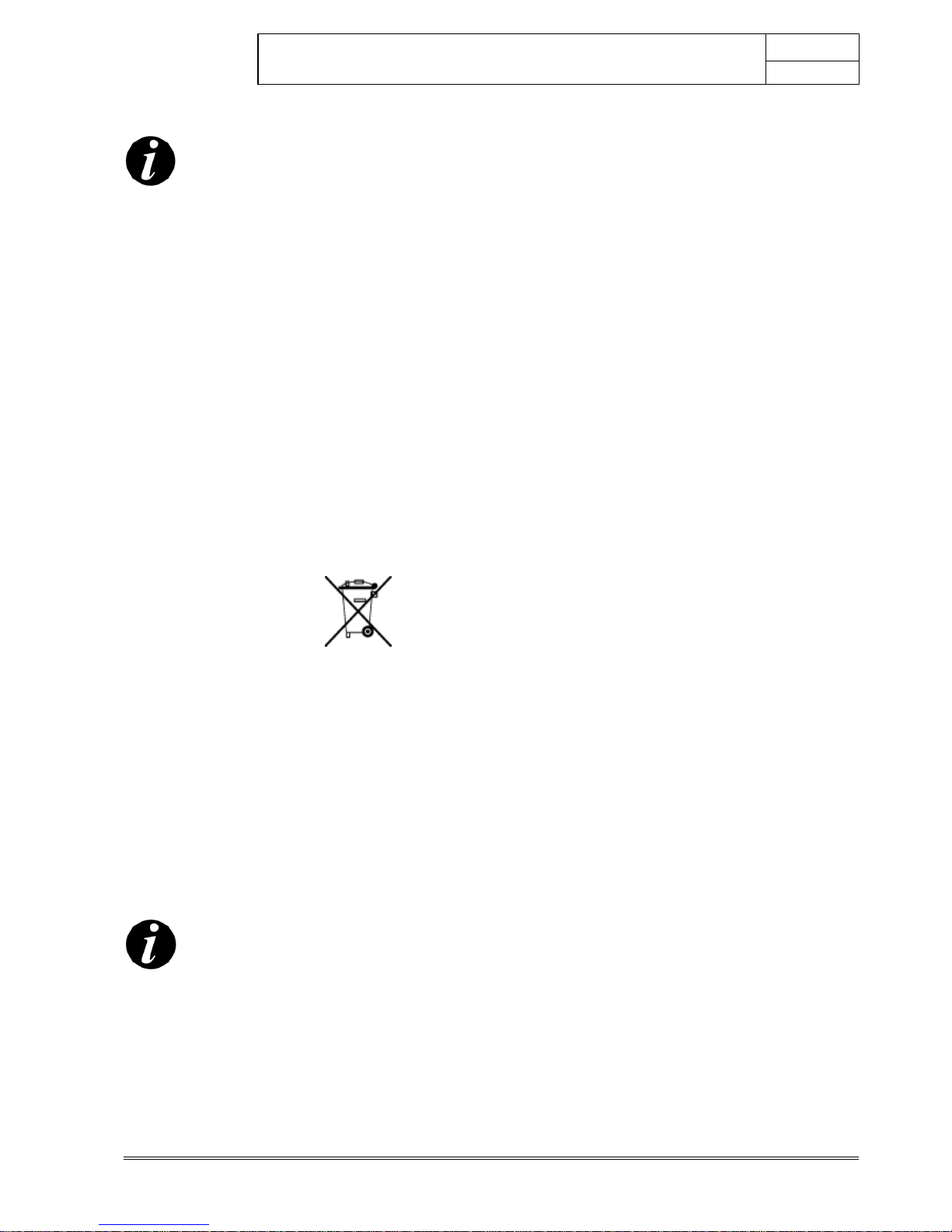
1.3. IMPORTANT INFORMATION FOR CORRECT DISPOSAL OF THE PRODUCT IN ACCORDANCE WITH EC
DIRECTIVE 2002/96/EC.............................................................................................................................8
1.4. GUARANTEE CONDITIONS ..............................................................................................................8
1.4.1. Limitations...............................................................................................................................9
1.4.2. Exclusions................................................................................................................................9
2. THEORETICAL NOTIONS FOR INSTALLATION ................................................................................10
2.1. Pellets..........................................................................................................................................10
2.2. PRECAUTIONS FOR INSTALLATION................................................................................................11
2.3. OPERATING AREA.........................................................................................................................12
2.3.1. Safe distances........................................................................................................................12
2.4. CONNECTION TO THE COMBURENT AIR INLET PIPE (1)..................................................................13
2.5. CONNECTION OF SMOKE DISCHARGE PIPE (2)...............................................................................13
2.6. CONNECTION TO THE FLUE PIPE...................................................................................................15
2.7. CONNECTION TO AN EXTERNAL FLUE WITH INSULATED OR DOUBLE-WALL PIPE.............................15
2.8. CONNECTION TO THE FLUE PIPE...................................................................................................15
2.9. OPERATING PROBLEMS CAUSED BY DRAUGHT DEFECTS IN THE FLUE.............................................16
3. INSTALLATION AND ASSEMBLY......................................................................................................17
3.1. DRAWINGS AND TECHNICAL CHARACTERISTICS............................................................................17
3.1.1. DALIA OYSTER.......................................................................................................................17
3.1.2. Technical characteristics .........................................................................................................18
3.2. PREPARATION AND UNPACK ING...................................................................................................19
3.3. LATERAL CLADDING ASSEMBLY.....................................................................................................21
3.4. MAKING THE ELECTRICAL CONNECTIONS......................................................................................21
4. OPERATION .....................................................................................................................................22
4.1. PRE-LIGHTING WARNINGS............................................................................................................22
4.2. PRE-LIGHTING CHECK ..................................................................................................................23
4.3. LOADING THE PELLETS.................................................................................................................23
4.4. DISPLAY PANEL AND COMMANDS..................................................................................................24
4.4.1. Control panel logic..................................................................................................................24
4.5. STOVE POWER SUPPLY.................................................................................................................26
4.6. FIRST LIGHTING ..........................................................................................................................26
4.6.1. Ignition/shutdown using the control panel (Key D)....................................................................26
4.7. OPERATING MODE........................................................................................................................26
4.7.1. Setting room temperature (Knob B).........................................................................................26
4.7.2. Setting the flame power (Knob C)............................................................................................26
4.7.3. Setting the hot air fan speed (Knob A).....................................................................................27
4.7.4. Note on first ignition...............................................................................................................27
4.8. SHUTDOWN MODE (Key D)...........................................................................................................27
4.9. CHOOSING THE TYPE OF PELLET LOAD (Key E)..............................................................................28
4.10. SUCTION UNIT SPEED SELECTION .............................................................................................28
4.11. VIEWING THE FLAME ................................................................................................................29
4.11.1. The shape..........................................................................................................................29
4.11.2. The colour..........................................................................................................................29
4.11.3. Character...........................................................................................................................29
4.12. Connection to a room thermostat................................................................................................30
4.13. Accessing the motherboard ........................................................................................................30
4.14. Operation with ECO-STOP..........................................................................................................31
4.15. Connection to programmable timed thermostat (optional RED accessory).......................................32
4.16. SAFETY DEVICES.......................................................................................................................33