ReDeal AP160N User manual

USER MANUAL
On-Line UPS
Model AP160N
1000VA/2000VA/3000VA
Uninterruptible Power Suppl S stem
ReDeal
ReDeal
ReDeal
www.redeal.pt

CONTENT
1. Safet and EMC Instructions .............................................................. 4
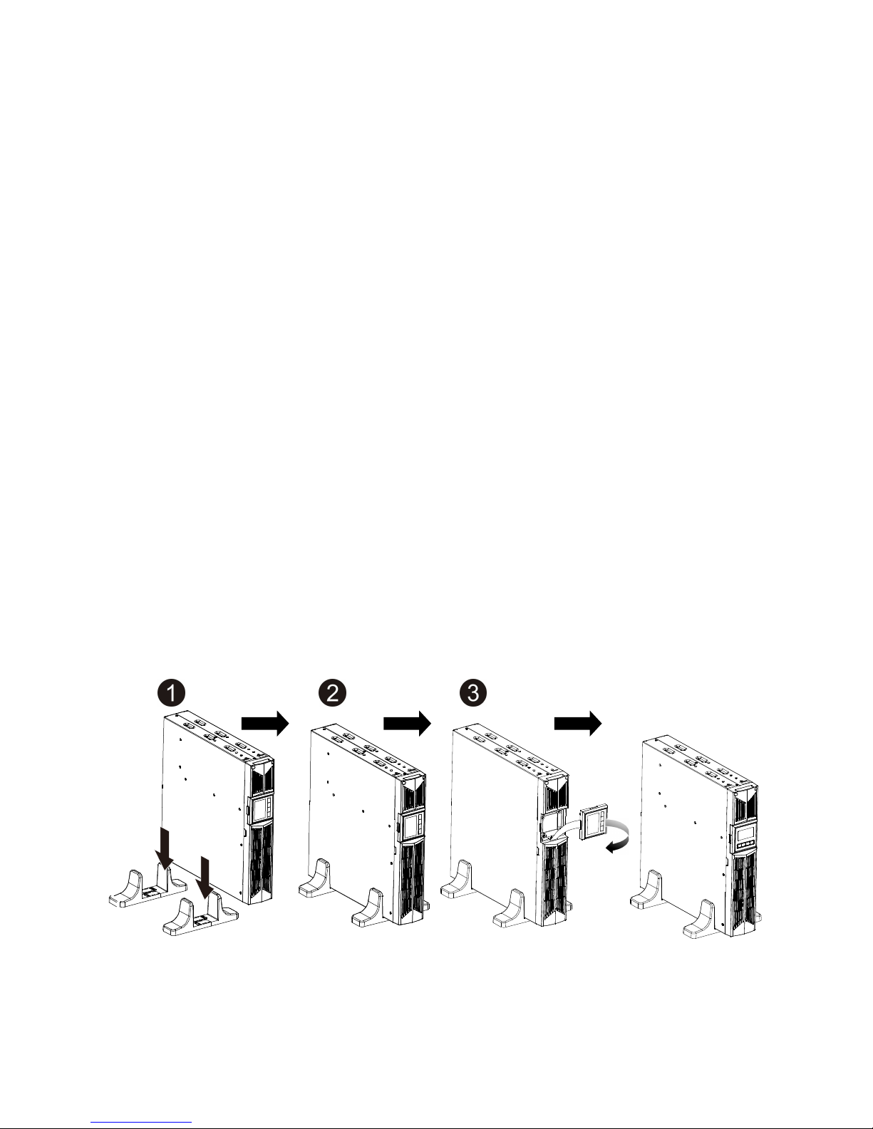
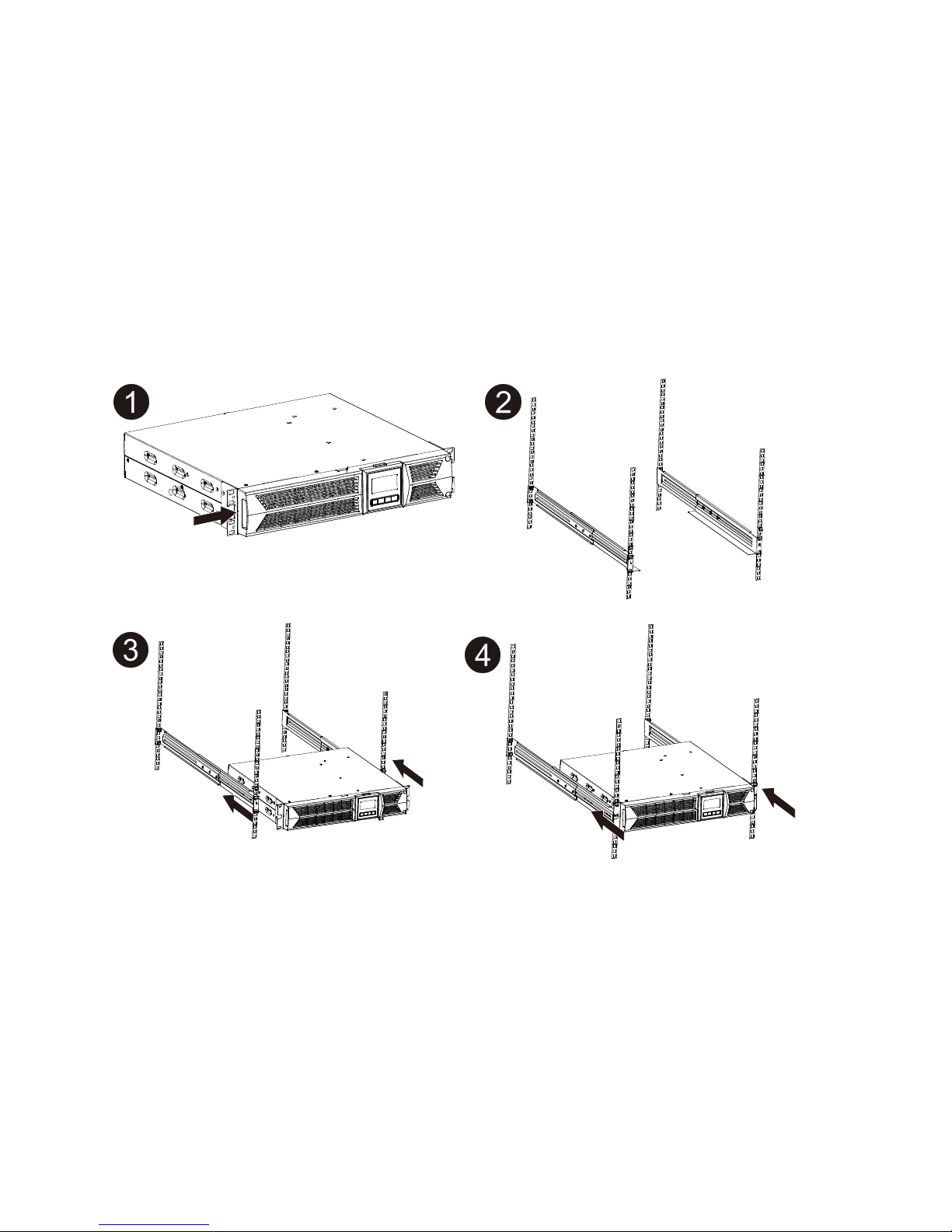
1.1 Installation ............................................................................................ 4
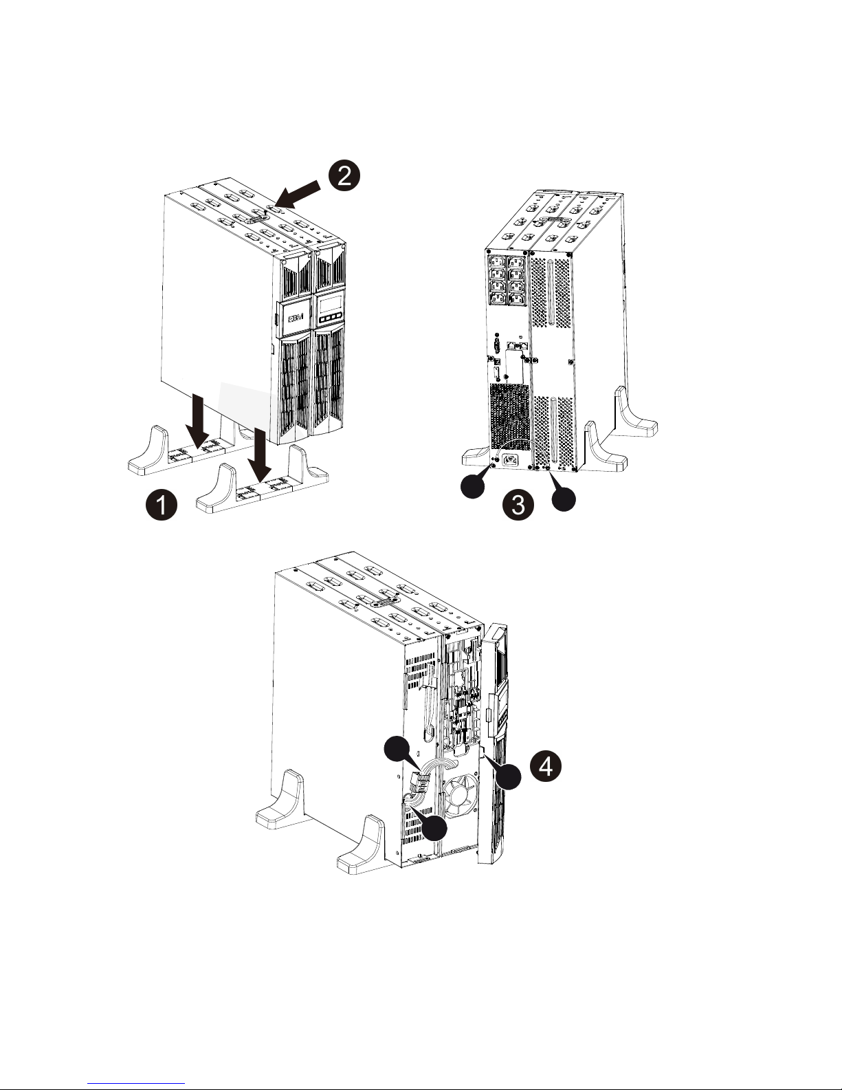
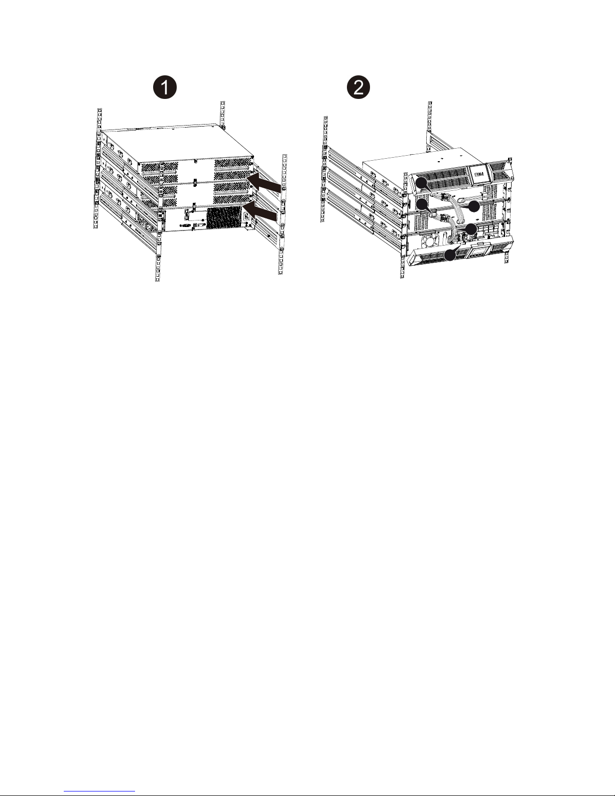
1.1.4 EBM Installation (Optional) ............................................................... 5
1.2 Operation.............................................................................................. 9
1.3 Maintenance, servicing and fa lts......................................................10
1.4 Transport ............................................................................................13
1.5 Storage ............................................................................................... 13
1.6 Standards ........................................................................................... 14
2. Description of Commonl Used S mbols .......................................15
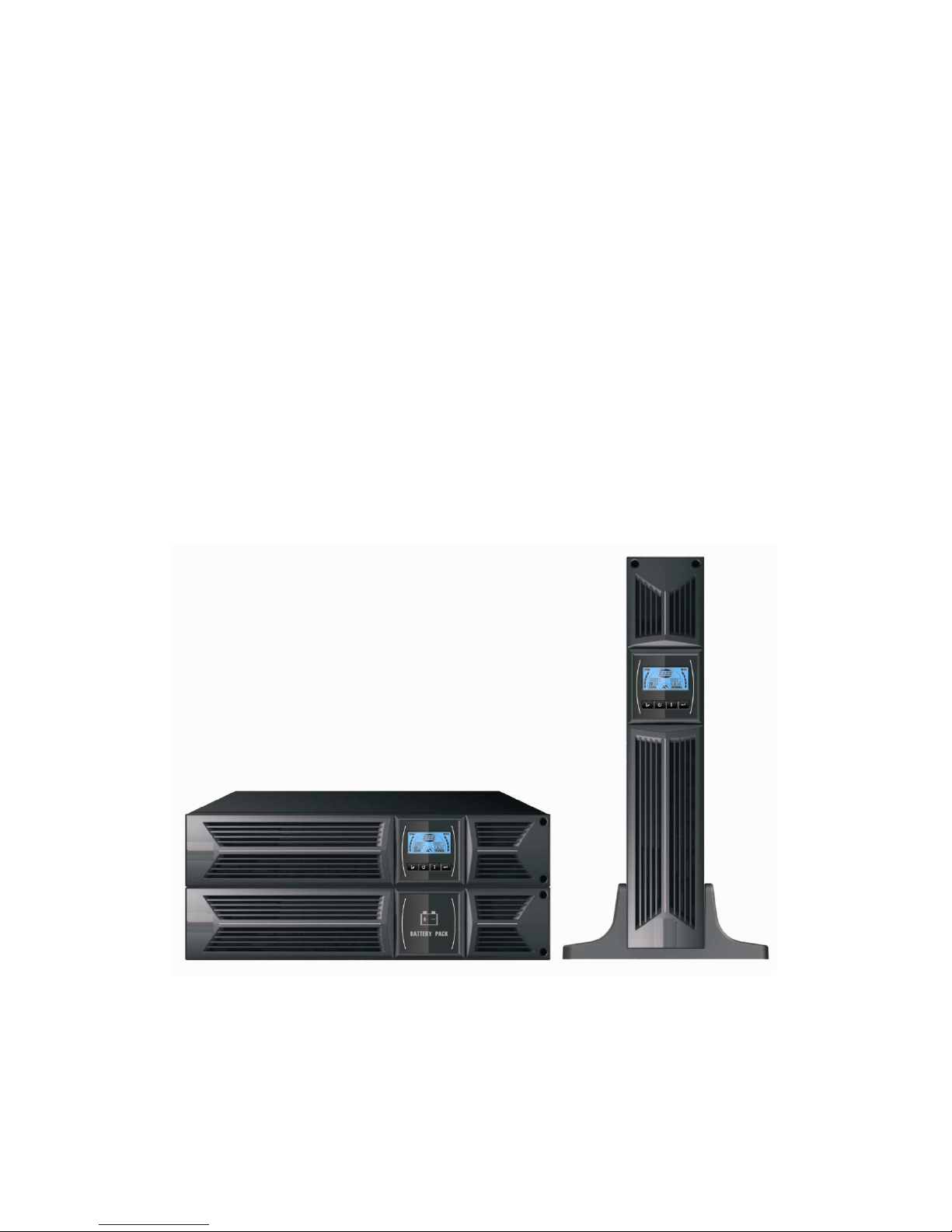
3. Introduction ........................................................................................ 16
4. Panel Description............................................................................... 17
5. Connection and Operation................................................................19
5.1 Inspection: ..........................................................................................19
5.2 Connection: ........................................................................................19
5.3 Battery charge:...................................................................................21
5.4 T rn on the UPS:................................................................................21
5.5 Test f nction: ...................................................................................... 21
5.6 T rn off the UPS:................................................................................22
5.7 A dible alarm m te f nction:.............................................................. 22
5.8 Operation proced re of external battery for long back p time model
(“S” model) ...............................................................................................22
6. Operating Mode for All Models.........................................................24
6.1 Line mode........................................................................................... 24
6.2 Battery mode ......................................................................................25
6.3 Bypass mode...................................................................................... 25
6.4 NO o tp t mode................................................................................. 26
6.5 EPO (Emergency Power Off) .............................................................26
6.6 ECO mode (Economy mode)............................................................. 26
6.7 Converter mode..................................................................................27
6.8 Abnormal mode ..................................................................................27
7. Setting b LCD Module......................................................................28
8. Trouble Shooting................................................................................30
9. Maintenance........................................................................................32
www.redeal.pt

9.1 Operation............................................................................................32
9.2 Storage ............................................................................................... 32
9.3 Battery Replace.................................................................................. 32
10. Technical Data .................................................................................. 33
10.1 Electrical specifications ....................................................................33
10.2 Operating Environment ....................................................................33
10.3 Typical back p time (Typical val es at 25°C in min tes:)....................33
10.4 Dimensions and weights ....................................................................34
11. Communication Port........................................................................34
11.1 RS-232 and USB comm nication ports ...........................................34
11.2 RS-232 port ......................................................................................35
11.3 USB port ...........................................................................................35
11.4 Installing a Serial Network Management Card (optional) ................ 35
12. Software ............................................................................................37
Appendix: Rear panel ............................................................................38
www.redeal.pt

4
1. Safet and EMC Instructions
1.1 Installation
★ See installation instr ctions before connecting to the s pply.
★ Condensation may occ r if the UPS is moved directly from a cold to a
warm environment. The UPS m st be absol tely dry before being
installed. Please allow an acclimatization time of at least two ho rs.
★ Do not install the UPS near water or in damp environment.
★ Do not install the UPS where it wo ld be exposed to direct s nlight or
near heat.
★ Do not connect appliances or items of eq ipment which wo ld overload
the UPS (e.g. laser printers, etc) to the UPS o tp t.
★ Place cables in s ch a way that no one can step on or trip over them.
★ Ass re to connect with the earth reliably.
★ Ass re external battery so rce m st be earthed.
★ Connect the UPS only to an earthed shockproof socket o tlet.
★ The b ilding wiring socket o tlet (shockproof socket o tlet) m st be
easily accessible to close to the UPS.
★ With the installation of the eq ipment, the s m of the leakage c rrent of
the UPS and the connected load does not exceed 1,5mA.
★ Do not block ventilation openings in the UPS’s ho sing. Ens re the air
vents on the front and rear of the UPS are not blocked. Allow at least
25cm of space on each side.
★ UPS has provided earthed terminal, in the final installed system
config ration, eq ipotential earth bonding to the external UPS battery
cabinets.
★ An appropriate disconnect device as short-circ it back p protection
sho ld be provided in the b ilding wiring installation. Please see the
disconnect device specification in chapter 5.2.
★ The eq ipment is powered by more than one so rce.
1.1.1 Inspection of Unit
Inspect the UPS pon receiving. If the UPS is apparently damaged d ring
the shipment, please keep the box and packing material in original form for
the carrier and notify the carrier and dealer immediately.
Please read caref lly the following ser man al and the safety
instr ctions before installing the nit or sing the nit!
www.redeal.pt

5
1.1.2 Unpacking the Cabinet
To npack the system:
1. Open the o ter carton and remove the accessories packaged with the
cabinet.
2. Caref lly lift the cabinet o t of the o ter carton and set it on a flat, stable
s rface.
3. Discard or recycle the packaging in a responsible manner, or store it for
f t re se.
1.1.3 UPS Setup
All model series are designed for tower and rack p rpose. They can be
installed into a 19 inches eq ipment rack. Please follow the instr ction for
Tower Set p and Rack-Mo nt Set p.
Tower setup
This series of UPS can be placed horizontally and vertically. As a tower
config ration, it is provided with the optional UPS stands to stabilize the UPS
when the UPS is positioned in vertical. The UPS stand m st be attached to the
bottom of the tower. Use the following proced re to install UPS in UPS stands.
1. Slide down the UPS vertically and p t two UPS stands at the end of the
tower.
2. Place down the UPS into two stands caref lly.
3. P ll o t the LCD box and rotate it in a clockwise direction to 90 degree and
then p sh it back in the front panel.
www.redeal.pt

5
Rack-mount setup
The series can be installed in 19 inches racks. Both the UPS and external
battery enclos re need 2U of val able rack space.
Use the following proced re to install UPS in a rack.
1. Align the mo nting ears with screw holes on the side of the UPS, and
tighten the screw.
2. Assemble the rack rails with the rack-mo nting.
3. Slide in the UPS into the rack rail and lock it in the rack enclos re.
4. Tighten the screw, and the load can then be connect
1.1.4 EBM Installation (Optional)
Connecting the EBM in Tower form:
1. Slide down the UPS and EBM vertically and place two UPS stands with the
extend part at the end of the tower.
2. Tighten the screw on the metal sheet for stabilization
3. Connect the Earth line from UPS (port A ) to EBM (port B)
4. Take off the front panel, and connect the battery terminal (A) from UPS to
EBM terminal (B) shown as below. Users need to remove the small gate(C)
www.redeal.pt

6
on side of the front panel to allow the o tlet wire of the EBM to pass thro gh
the gate and then reassemble front panel.
B
A
C
B
A
www.redeal.pt

7
Connecting the EBM in a rack form
1. Using the same method as assembling UPS in a rack form, assemble EBM
into the rack-mo nting on the top or bottom of the UPS.
2. Connect the earth line from UPS (port A ) to EBM (port B )
3. Take off the LCD box, and nscrew the internal screws.
4. Take off the front panel, and connect the battery terminal (A) from UPS to
EBM terminal (B) shown as below. Users need to remove the small gate(C)
on side of the front panel to allow the o tlet wire of the EBM to pass thro gh
the gate and then reassemble front panel.
5. After installing the UPS into rack, the load can then be connected to UPS.
Please make s re the load eq ipment is t rned off before pl gging all loads
into the o tp t receptacle
Connecting the Multiple EBMs
1KVA / 2KVA and 3KVA UPS incl de external battery port that allows sers to
connect m ltiple EBM in order to provide additional back p time. Follow the
proced re to install m ltiple EBM as below.
A
B
BA
C
Unscrew
Unscrew
5
www.redeal.pt

8
Connecting multiple EBMs in Tower form
1. Connect Earth line between UPS and the first EBM, and then connect Earth
Line between the first EBM and the second EBM.
2. Take off the front panel, and connect the battery terminal (A) from UPS to
EBM terminal (B) shown as below. And then connect the battery terminal (D)
from the first EBM to the battery terminal (E) from the second EBM. Users
need to remove the small gate(C) on side of the front panel to allow the
o tlet wire of the EBM to pass thro gh the gate and then reassemble front
panel.
Connecting the Multiple EBMs in rack form
1. Connect Earth line between UPS and the first EBM, and then connect
Earth Line between the first EBM and the second EBM.
2. Take off the front panel, and connect the battery terminal (A) from UPS to
EBM terminal (B) shown as below. And then connect the battery terminal
(D) from the first EBM to the battery terminal (E) from the second EBM.
Users need to remove the small gate(C) on side of the front panel to allow
the o tlet wire of the EBM to pass thro gh the gate and then reassemble
front panel.
B
C
A
D
E
www.redeal.pt

9
Note: Three or more EBMs can be connected to the UPS in the same way as
shown above.
Note: After connect the EBMs, please do not forget to set the n mber of EBMs
on LCD, please refer to chapter 7 “Setting by LCD mod le” for setting method.
If se the nonstandard EBMs,
please call local dealer or distrib tor for setting
method.
1.2 Operation
★ Do not disconnect the mains cable on the UPS or the b ilding wiring
socket (gro nded shockproof socket) d ring operation as this wo ld
remove the gro nd to the UPS and of all connected loads.
★ The UPS feat res its own, internal c rrent so rce (batteries). Yo may be
electric shock when yo to ch the UPS o tp t sockets or o tp t terminal
block even if the UPS is not connected to the b ilding wiring socket.
★ In order to f lly disconnect the UPS, first press the OFF b tton to t rn off
the UPS, then disconnect the mains lead.
★ Ens re that no liq id or other foreign objects can enter the UPS.
★ Do not remove the enclos re. This system is to be serviced by q alified
service personnel only.
★ Remove the protective panel only after disconnecting the terminal
connections.
★ Use No. 12 AWG (for 3K-KS inp t wire), 90°C copper wire and 4.4 lb-in
E
B
C
A
D
www.redeal.pt

10
Torq e force when connecting to terminal block.
★ Use No. 10AWG (for all models battery wire), 90°C copper wire and
Anderson PP45 connectors for ser’s external battery cabinet.
1.3 Maintenance, servicing and faults
★ The UPS operates with hazardo s voltages. Repairs may be carried o t
only by q alified maintenance personnel.
★ Ca tion - risk of electric shock. Even after the nit is disconnected from the
mains power s pply (b ilding wiring socket), components inside the UPS
are still connected to the battery which are potentially dangero s.
★ Before carrying o t any kind of service and/or maintenance, disconnect the
batteries. Verify that no c rrent is present and no hazardo s voltage
exists in the capacitor or BUS capacitor terminals.
★ Batteries m st be replaced only by q alified personnel.
★ Ca tion - risk of electric shock. The battery circ it is not isolated from the
inp t voltage. Hazardo s voltages may occ r between the battery
terminals and the gro nd. Verify that no voltage is present before servicing!
★ Batteries have a high short-circ it c rrent and pose a risk of shock. Take
all preca tionary meas res specified below and any other meas res
necessary when working with batteries:
★ - remove all jewellery, wristwatches, rings and other metal objects
★ - se only tools with ins lated grips and handles.
★ When changing batteries, replace with the same q antity and the same
type of batteries.
★ Do not attempt to dispose of batteries by b rning them. It co ld ca se
explosion.
★ Do not open or destroy batteries. Effl ent electrolyte can ca se inj ry to
the skin and eyes. It may be toxic.
★ Please replace the f se only by a f se of the same type and of the same
amperage in order to avoid fire hazards.
★ Do not dismantle the UPS, except the q alified maintenance personnel.
1.3.1 UPS and Batter Care
For the best preventive maintenance, keep the area aro nd the UPS clean
and d st-free. If the atmosphere is very d sty, clean the o tside of the system
www.redeal.pt

11
with a vac m cleaner. For long battery life, keep the UPS at an ambient
temperat re of 25°C (77°F)
1.3.2 Storing the UPS and Batteries
When the UPS is intended to store for a long period, recharge the battery
every 6 months by connecting the UPS to tility power. The batteries charge to
90% capacity in approximately 4 ho rs. However, it is recommended that the
batteries charge for 48 ho rs after long-term storage.
1.3.3 Time to Replace Batteries
When the discharging time is less than 50% of specified after f ll charged, the
battery may need to be replaced. Please check the battery connection or
contact yo r local dealer to order new battery.
WARNING:
T rn off the UPS and disconnect the tility power cord from the wall o tlet.
Servicing sho ld be performed by q alified service personnel
knowledgeable of batteries and req ired preca tions. Keep na thorized
personnel away from batteries
Batteries can present a risk of electrical shock or b rn from high short
circ it c rrent. The following preca tions sho ld be observed:
1. Remove watches, rings, or other metal objects.
2. Use tools with ins lated handles.
3. Do not lay tools or metal parts on top of batteries.
4. Wear r bber gloves and boots.
5. Disconnect the charging so rce prior to connecting or disconnecting
battery terminal.
When replacing batteries, replace with the same type and n mber of
batteries or battery packs. Contact yo r service representative to order
new batteries.
Do not dispose of battery in a fire. Batteries may explode when exposed to
flame.
Proper disposal of batteries is req ired. Refer to yo r local codes for
disposal req irements.
Do not open or m tilate the battery. Released toxic electrolyte is harmf l to
skin and eyes.
www.redeal.pt

12
1.3.4 Replacing UPS Internal Batteries
Follow the steps and Charts as below to replace batteries:
1. Take off the LCD box, and remove the screws.
2. Slide and P ll the front panel leftward and then take it off.
3. Disconnect the cable from the UPS and battery pack.
4. Remove the right inner battery bracket.
5. P ll the battery pack o t onto flat area.
6. Install new battery pack into UPS.
7. Screw p the battery bracket and reconnect the battery cable A and B
8. Re-install the front panel back to UPS.
Note: If yo are not q alified service personnel to replace the battery, do not
attempt to open the battery cabin. Please call local dealer or distrib tor
immediately.
5
7
www.redeal.pt

13
1.3.5 Testing New Batteries
For a battery test, please check:
The batteries m st be f lly charged.
The UPS m st be in Normal mode with no active alarms.
Don’t take on/off the load.
To test batteries:
1. Connect the UPS to tility power for at least 48 ho rs to charge the
batteries.
2. Press and hold the “I” b tton 1 second to start the battery test on line mode
or HE mode. The stat s display string shows “TEST”
1.3.6 Rec cling the Used Batter :
To recycle properly the sed battery, please do not discard the UPS, battery
pack and batteries into the trash bin. Please follow yo r local laws and
reg lations; yo may contact yo r local recycling waste management center
for f rther information to dispose properly of the sed UPS, battery pack, and
batteries.
1.4 Transport
★ Please transport the UPS only in the original packaging (to protect against
shock and impact).
1.5 Storage
★ The UPS m st be stockpiled in the room where it is ventilated and dry.
Warning:
Never dispose the batteries in a fire. It may explode.
Do not open or m tilate the batteries. Released electrolyte is harmf l
to the skins and eyes. It may be toxic. A battery can present a risk of
electrical shock and high short circ it c rrent.
www.redeal.pt

14
1.6 Standards
* Safet
IEC/EN 62040-1-1
* EMI
Cond cted Emission..........................:IEC/EN 62040-2 Category C1
Radiated Emission.............................:IEC/EN 62040-2 Category C1
Harmonic C rrent...............................:IEC/EN 61000-3-2
Voltage Fl ct ation and Flicker..........:IEC/EN 61000-3-3
*EMS
ESD...................................................:IEC/EN 61000-4-2 Level 3
RS.....................................................:IEC/EN 61000-4-3 Level 3
EFT....................................................:IEC/EN 61000-4-4 Level 4
SURGE.............................................:IEC/EN 61000-4-5 Level 4
CS……………………………………...:IEC/EN 61000-4-6 Level 3
MS……………………………………..: IEC/EN 61000-4-8 Level 3
Voltage Dips………………………….: IEC/EN 61000-4-11
Low Freq ency Signals.....................:IEC/EN 61000-2-2
www.redeal.pt

15
2. Description of Commonl Used S mbols
Some or all of the following symbols may be sed in this man al. It is advisable to
familiarize yo rself with them and nderstand their meaning:
www.redeal.pt

16
3. Introduction
This On-Line-Series is an ninterr ptible power s pply incorporating
do ble-converter technology. It provides perfect protection specifically for
Novell, Windows NT and UNIX servers.
The do ble-converter principle eliminates all mains power dist rbances. A
rectifier converts the alternating c rrent from the socket o tlet to direct
c rrent. This direct c rrent charges the batteries and powers the inverter. On
the basis of this DC voltage, the inverter generates a sin soidal AC voltage,
which permanently s pplies the loads.
Comp ters and periphery are th s powered entirely by the mains voltage. In
the event of power fail re, the maintenance-free batteries power the inverter.
This man al covers the UPS listed as follows. Please confirm whether it is
the model yo intend to p rchase by performing a vis al inspection of the
Model No. on the rear panel of the UPS.
“KS” Model: Extended back p time
Model No. T pe Model No. T pe
1K 1K-KS
2K 2K-KS
3K
Standard
3K-KS
Extended back p
time
www.redeal.pt

17
4. Panel Description
The Displa Panel
Switch Function
ON
Button
T rn on UPS system: By pressing the ON-B tton “I” the UPS system
is t rned on.
Deactivate aco stic alarm: By pressing this B tton an aco stic alarm
can be deactivated in the battery mode. By short to ch this B tton all
aco stic alarms can be deactivated in all mode.
Do the battery test: By pressing this B tton the UPS can do the
battery test in the Line mode or ECO mode or Converter mode.
OFF
Button
When mains power is normal, the UPS system switches to No o tp t
or Bypass mode by pressing OFF-B tton “ “, and the inverter is off.
At this moment, if Bypass is enabled, then the o tp t sockets are
s pplied with voltage via the bypass if the mains power is available.
Deactivate aco stic alarm: By pressing this B tton an aco stic alarm
can be deactivated in the bypass mode.
Release the UPS from fa lt mode and EPO stat s.
Select
Button
Enter
Button
The o tp t voltage, freq ency, Bypass disable/enable and operating
mode in No o tp t or Bypass mode, Two Load segments in o tp t
mode, Battery string in all mode, co ld be selected by pressing
Select-B tton, and confirmed by pressing Enter-B tton.
www.redeal.pt

18
The LCD Displa
Displa Function Displa Function
Inp t Information O tp t Information
It indicates inp t
voltage/freq ency val e, which
are displayed alternately.
It indicates o tp t
voltage/freq ency val e, which
are displayed alternately.
It indicates the inp t is
connected with mains, and the
inp t power is s pplied from
the mains.
It indicates the O tp t pl g.
It indicates the N mber of the
inp t s pplied from the mains.
It indicates the N mber of the
o tp t connected with load.
Battery Information Load Information
It indicates the battery capacity.
Every grid represents the
capacity of 20%.
It indicates the load level. Every
grid represents the level of
20%.
Mode/Fa lt/Warning Information Else
It indicates the UPS is in setting
mode.
It Indicates the operating mode
or Fa lt kind or Warning kind,
several warning kinds at the
same time co ld be displayed
alternately.
It indicates the UPS is in Fa lt
mode or has some warnings.
www.redeal.pt

19
5. Connection and Operation
5.1 Inspection:
Inspect the packaging carton and its contents for damage. Please inform the
transport agency immediately sho ld yo find signs of damage.
Please keep the packaging in a safe place for f t re se.
Note: Please ens re that the incoming feeder is isolated and sec red to
prevent it from being switched back on again.
5.2 Connection:
(1) UPS Input Connection
If the UPS is connected via the power cord, please se a proper socket with
protection against electric c rrent, the ser can refer to below table. If the
UPS is connected via wires, it is recommended to select the 2.5mm
2
wire,
and the “GND” terminal sho ld be gro nded first.
The UPS System has no inp t breaker on the standard cabinet. When
installing the UPS, the ser needs to connect the external breakers and
protective components in the inp t terminals. It is recommended to select the
NFB(Non-F se Breaker) instead of the traditional combination kit incl ding
breaker and f se.
When selecting the NFB, the ser can refer to below table.
UPS INPUT NFB & Power Cord & Socket
Model No.
VOLTAGE CURRENT
1K & 1K-KS 300Vac 10A
2K & 1K-KS 300Vac 16A
3K & 1K-KS 300Vac 20A
The system may be installed and wired only by q alified electricians
in accordance with a
pplicable safety reg lations!
When installing the electrical wiring, please note the nominal
amperage of yo r incoming feeder
.
www.redeal.pt
Table of contents
Other ReDeal UPS manuals
Popular UPS manuals by other brands

Emerson
Emerson Liebert APM 90 user manual

EFOY
EFOY EFOY Pro 600 Operation and installation manual

MAKELSAN
MAKELSAN Lion X 650 user manual

Toshiba
Toshiba 1600XP SERIES Installation and operation manual

Middle Atlantic Products
Middle Atlantic Products UPS-OL3000R quick start guide

Emerson
Emerson SOLAHD S4KC Series instruction manual